headlamp NISSAN TIIDA 2007 Service Repair Manual
[x] Cancel search | Manufacturer: NISSAN, Model Year: 2007, Model line: TIIDA, Model: NISSAN TIIDA 2007Pages: 5883, PDF Size: 78.95 MB
Page 5817 of 5883
![NISSAN TIIDA 2007 Service Repair Manual DIAGNOSIS SYSTEM (BCM)
WW-15
< FUNCTION DIAGNOSIS >
C
D
E
F
G
H
I
J
K
MA
B
WW
N
O
P
ACTIVE TEST
FR WIPER HI
[OFF/ON]
Each switch status that BCM judges from the combination switch reading function. FR](/img/5/57395/w960_57395-5816.png "NISSAN TIIDA 2007 Service Repair Manual DIAGNOSIS SYSTEM (BCM)
WW-15
< FUNCTION DIAGNOSIS >
C
D
E
F
G
H
I
J
K
MA
B
WW
N
O
P
ACTIVE TEST
FR WIPER HI
[OFF/ON]
Each switch status that BCM judges from the combination switch reading function. FR")
DIAGNOSIS SYSTEM (BCM)
WW-15
< FUNCTION DIAGNOSIS >
C
D
E
F
G
H
I
J
K
MA
B
WW
N
O
P
ACTIVE TEST
FR WIPER HI
[OFF/ON]
Each switch status that BCM judges from the combination switch reading function. FR WIPER LOW
[OFF/ON]
FR WIPER INT
[OFF/ON]
FR WASHER SW
[OFF/ON]
H/L WASH SW
[OFF/ON]NOTE:
The item is indicated, but not monitored.
INT VOLUME
[1 − 7] Each switch status that BCM judges from the combination switch reading function.
FR WIPER STOP
[OFF/ON]Front wiper motor (stop position) status received from IPDM E/R with CAN communica-
tion.
VEHICLE SPEED
[km/h]The value of the vehicle speed signal received from combination meter with CAN com-
munication.
RR WIPER ON
[OFF/ON]
Each switch status that BCM judges from the combination switch reading function. RR WIPER INT
[OFF/ON]
RR WASHER SW
[OFF/ON]
RR WIPER STOP
[OFF/ON]Rear wiper motor (stop position) status input from the rear wiper motor. Monitor Item
[Unit]Description
Test item Operation Description
FR WIPERHITransmits the front wiper request signal (HI) to IPDM E/R with CAN communication to op-
erate the front wiper HI operation.
LOTransmits the front wiper request signal (LO) to IPDM E/R with CAN communication to
operate the front wiper LO operation.
INTTransmits the front wiper request signal (INT) to IPDM E/R with CAN communication to
operate the front wiper INT operation.
OFF Stops transmitting the front wiper request signal to stop the front wiper operation.
RR WIPERON Outputs the voltage to operate the rear wiper motor.
OFF Stops the voltage to stop rear wiper motor operation.
HEADLAMP WASH-
ERONTransmits the headlamp washer request signal to IPDM E/R with CAN communication to
operate the headlamp washer operation.
Page 5818 of 5883

WW-16
< FUNCTION DIAGNOSIS >
DIAGNOSIS SYSTEM (IPDM E/R)
DIAGNOSIS SYSTEM (IPDM E/R)
Diagnosis DescriptionINFOID:0000000001366606
AUTO ACTIVE TEST
Refer to PCS IPDM E/R AUTO ACTIVE TEST.
CONSULT - III Function (IPDM E/R)INFOID:0000000001366607
APPLICATION ITEM
CONSULT-III performs the following functions via CAN communication with IPDM E/R.
SELF DIAGNOSTIC
Refer to PCS-28, "DTCIndex".
DATA MONITOR
Monitor item
ACTIVE TEST
Te s t i t e m
Diagnosis mode Description
ECU Identification Allows confirmation of IPDM E/R part number.
Self Diagnostic Result Displays the diagnosis results judged by IPDM E/R.
Data Monitor Displays the real-time input/output data from IPDM E/R input/output data.
Active Test IPDM E/R can provide a drive signal to electronic components to check their operations.
CAN Diag Support Monitor The results of transmit/receive diagnosis of CAN communication can be read.
Monitor Item
[Unit]MAIN
SIGNALSDescription
HL WASHER REQ
[Off/On]Displays the status of the headlamp washer request signal received from BCM via CAN
communication.
FR WIP REQ
[Stop/1LOW/Low/Hi]×Displays the status of the front wiper request signal received from BCM via CAN com-
munication.
WIP AUTO STOP
[STOP P/ACT P]×Displays the status of the front wiper auto stop signal judged by IPDM E/R.
WIP PROT
[Off/BLOCK]×Displays the status of the front wiper fail-safe operation judged by IPDM E/R.
IGN RLY
[Off/On]×Displays the status of the ignition relay judged by IPDM E/R.
IGN ON SW
[Off/On]Displays the status of the ignition switch judged by IPDM E/R.
Test item Operation Description
FRONT WIPEROff OFF
Lo Operates the front wiper relay.
Hi Operates the front wiper relay and front wiper high relay.
HEAD LAMP WASHER On Operates the headlamp washer relay for 1 second.
EXTERNAL LAMPSOff OFF
TAIL Operates the tail lamp relay.
Lo Operates the headlamp low relay.
HiOperates the headlamp low relay and ON/OFF the headlamp high relay at 1 sec-
ond intervals.
Fog Operates the front fog lamp relay.
Page 5819 of 5883

WIPER AND WASHER FUSE, FUSIBLE LINK
WW-17
< COMPONENT DIAGNOSIS >
C
D
E
F
G
H
I
J
K
MA
B
WW
N
O
P
COMPONENT DIAGNOSIS
WIPER AND WASHER FUSE, FUSIBLE LINK
DescriptionINFOID:0000000001366608
Fuse, fusible link list
Diagnosis ProcedureINFOID:0000000001366609
1. CHECK FUSES AND FUSIBLE LINK
Check that the following fuses and fusible link are not blown.
Is the fuse or fusible link blown?
YES >> Replace the fuse or fusible link after repairing the applicable circuit.
NO >> The fuse or fusible link is normal.
Unit Location Fuse No. Capacity
Front wiper motor IPDM E/R 39 30 A
Front and rear washer motor Fuse block (J/B) 4 15 A
Headlamp washer motor Fuse and fusible link box L 30 A
Unit Location Fuse No. Capacity
Front wiper motor IPDM E/R 39 30 A
Front and rear washer motor Fuse block (J/B) 4 15 A
Headlamp washer motor Fuse and fusible link box L 30 A
Page 5834 of 5883
WW-32
< COMPONENT DIAGNOSIS >
HEADLAMP WASHER RELAY
HEADLAMP WASHER RELAY
Component InspectionINFOID:0000000001366625
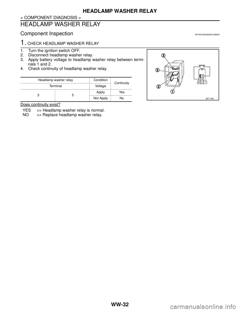
1. CHECK HEADLAMP WASHER RELAY
1. Turn the ignition switch OFF.
2. Disconnect headlamp washer relay.
3. Apply battery voltage to headlamp washer relay between termi-
nals 1 and 2.
4. Check continuity of headlamp washer relay.
Does continuity exist?
YES >> Headlamp washer relay is normal.
NO >> Replace headlamp washer relay.
Headlamp washer relay Condition
Continuity
Terminal Voltage
35Apply Yes
Not Apply No
SEF145X
Page 5835 of 5883
HEADLAMP WASHER CIRCUIT
WW-33
< COMPONENT DIAGNOSIS >
C
D
E
F
G
H
I
J
K
MA
B
WW
N
O
P
HEADLAMP WASHER CIRCUIT
Component Function CheckINFOID:0000000001366626
1. CHECK HEADLAMP WASHER OPERATION
CONSULT-III ACTIVE TEST
1. Select "HEAD LAMP WASHER" of IPDM E/R active test item.
2. While operating the test item, check headlamp washer operation.
Is the headlamp washer operation normally?
YES >> Headlamp washer circuit is normal.
NO >> Refer to WW-33, "
Diagnosis Procedure".
Diagnosis ProcedureINFOID:0000000001366627
1. CHECK HEADLAMP WASHER FUSIBLE LINK
1. Turn the ignition switch OFF.
2. Check that the following fusible link is not blown.
Is the fusible link blown?
YES >> Replace the fusible link after repairing the applicable circuit.
NO >> GO TO 2
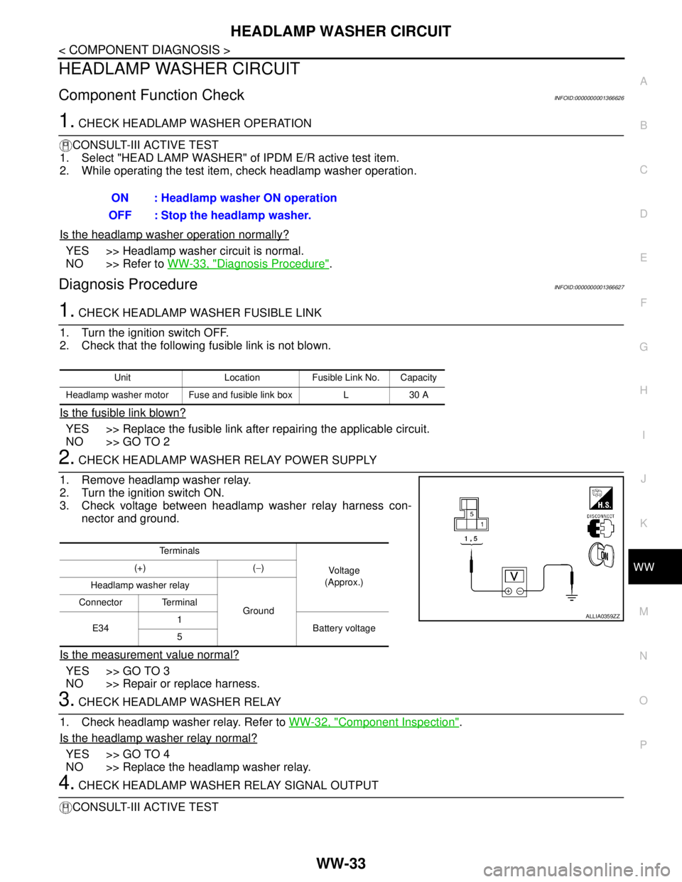
2. CHECK HEADLAMP WASHER RELAY POWER SUPPLY
1. Remove headlamp washer relay.
2. Turn the ignition switch ON.
3. Check voltage between headlamp washer relay harness con-
nector and ground.
Is the measurement value normal?
YES >> GO TO 3
NO >> Repair or replace harness.
3. CHECK HEADLAMP WASHER RELAY
1. Check headlamp washer relay. Refer to WW-32, "
Component Inspection".
Is the headlamp washer relay normal?
YES >> GO TO 4
NO >> Replace the headlamp washer relay.
4. CHECK HEADLAMP WASHER RELAY SIGNAL OUTPUT
CONSULT-III ACTIVE TESTON : Headlamp washer ON operation
OFF : Stop the headlamp washer.
Unit Location Fusible Link No. Capacity
Headlamp washer motor Fuse and fusible link box L 30 A
Te r m i n a l s
Vo l ta g e
(Approx.) (+) (−)
Headlamp washer relay
Ground Connector Terminal
E341
Battery voltage
5
ALLIA0359ZZ
Page 5836 of 5883
WW-34
< COMPONENT DIAGNOSIS >
HEADLAMP WASHER CIRCUIT
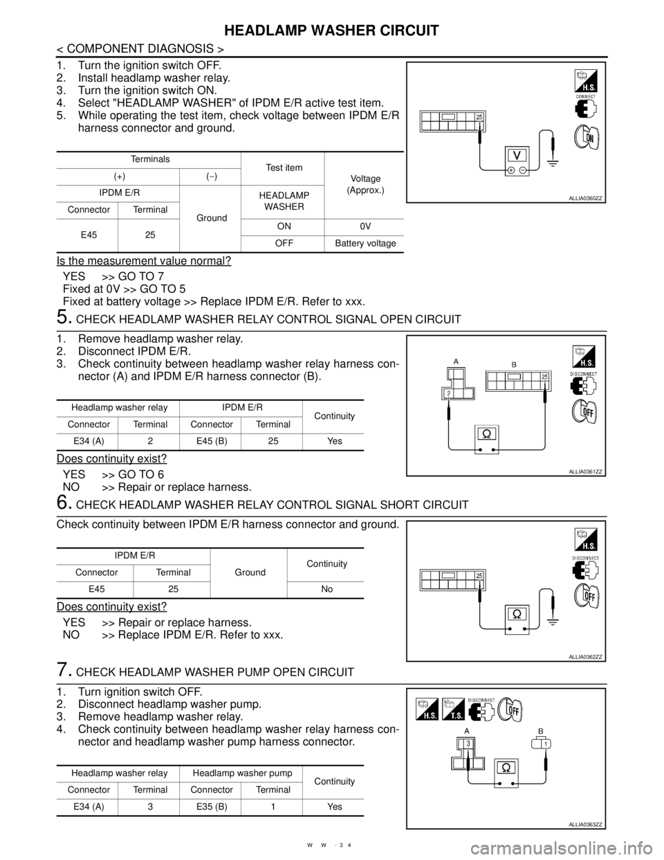
1. Turn the ignition switch OFF.
2. Install headlamp washer relay.
3. Turn the ignition switch ON.
4. Select "HEADLAMP WASHER" of IPDM E/R active test item.
5. While operating the test item, check voltage between IPDM E/R
harness connector and ground.
Is the measurement value normal?
YES >> GO TO 7
Fixed at 0V >> GO TO 5
Fixed at battery voltage >> Replace IPDM E/R. Refer to xxx.
5. CHECK HEADLAMP WASHER RELAY CONTROL SIGNAL OPEN CIRCUIT
1. Remove headlamp washer relay.
2. Disconnect IPDM E/R.
3. Check continuity between headlamp washer relay harness con-
nector (A) and IPDM E/R harness connector (B).
Does continuity exist?
YES >> GO TO 6
NO >> Repair or replace harness.
6. CHECK HEADLAMP WASHER RELAY CONTROL SIGNAL SHORT CIRCUIT
Check continuity between IPDM E/R harness connector and ground.
Does continuity exist?
YES >> Repair or replace harness.
NO >> Replace IPDM E/R. Refer to xxx.
7. CHECK HEADLAMP WASHER PUMP OPEN CIRCUIT
1. Turn ignition switch OFF.
2. Disconnect headlamp washer pump.
3. Remove headlamp washer relay.
4. Check continuity between headlamp washer relay harness con-
nector and headlamp washer pump harness connector.
Te r m i n a l s
Te s t i t e m
Vo l ta g e
(Approx.) (+) (−)
IPDM E/R
GroundHEADLAMP
WASHER
Connector Terminal
E45 25ON 0V
OFF Battery voltage
ALLIA0360ZZ
Headlamp washer relay IPDM E/R
Continuity
Connector Terminal Connector Terminal
E34 (A) 2 E45 (B) 25 Yes
ALLIA0361ZZ
IPDM E/R
GroundContinuity
Connector Terminal
E45 25 No
ALLIA0362ZZ
Headlamp washer relay Headlamp washer pump
Continuity
Connector Terminal Connector Terminal
E34 (A) 3 E35 (B) 1 Yes
ALLIA0363ZZ
Page 5837 of 5883
HEADLAMP WASHER CIRCUIT
WW-35
< COMPONENT DIAGNOSIS >
C
D
E
F
G
H
I
J
K
MA
B
WW
N
O
P
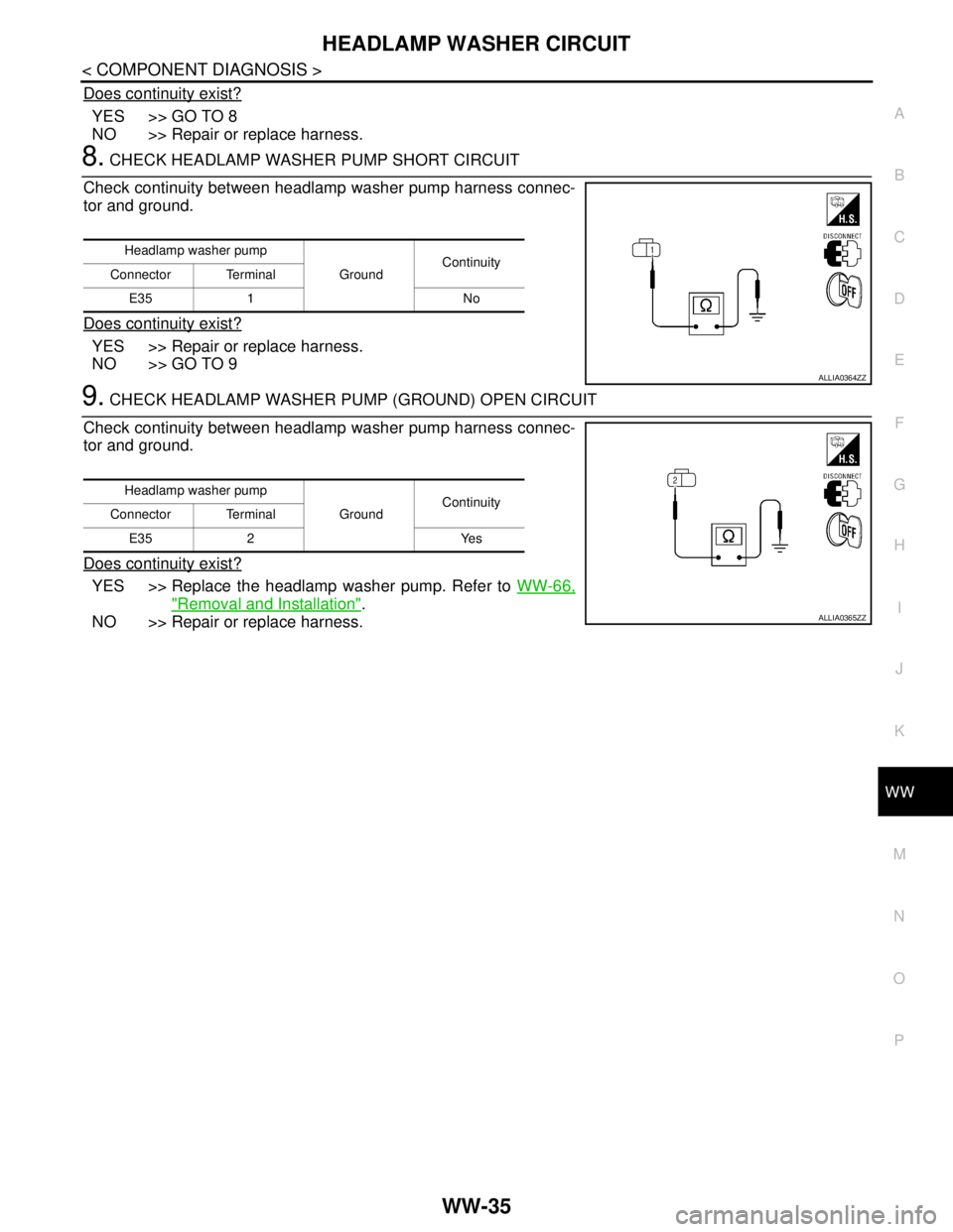
Does continuity exist?
YES >> GO TO 8
NO >> Repair or replace harness.
8. CHECK HEADLAMP WASHER PUMP SHORT CIRCUIT
Check continuity between headlamp washer pump harness connec-
tor and ground.
Does continuity exist?
YES >> Repair or replace harness.
NO >> GO TO 9
9. CHECK HEADLAMP WASHER PUMP (GROUND) OPEN CIRCUIT
Check continuity between headlamp washer pump harness connec-
tor and ground.
Does continuity exist?
YES >> Replace the headlamp washer pump. Refer to WW-66,
"Removal and Installation".
NO >> Repair or replace harness.
Headlamp washer pump
GroundContinuity
Connector Terminal
E35 1 No
ALLIA0364ZZ
Headlamp washer pump
GroundContinuity
Connector Terminal
E35 2 Yes
ALLIA0365ZZ
Page 5849 of 5883
HEADLAMP WASHER SYSTEM
WW-47
< COMPONENT DIAGNOSIS >
C
D
E
F
G
H
I
J
K
MA
B
WW
N
O
P
HEADLAMP WASHER SYSTEM
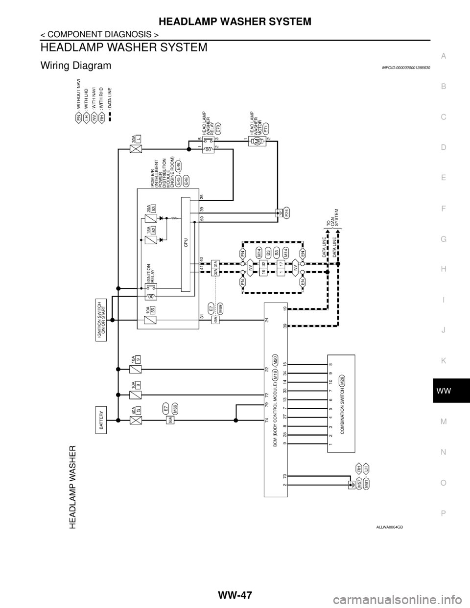
Wiring DiagramINFOID:0000000001366630
ALLWA0064GB
Page 5850 of 5883
WW-48
< COMPONENT DIAGNOSIS >
HEADLAMP WASHER SYSTEM
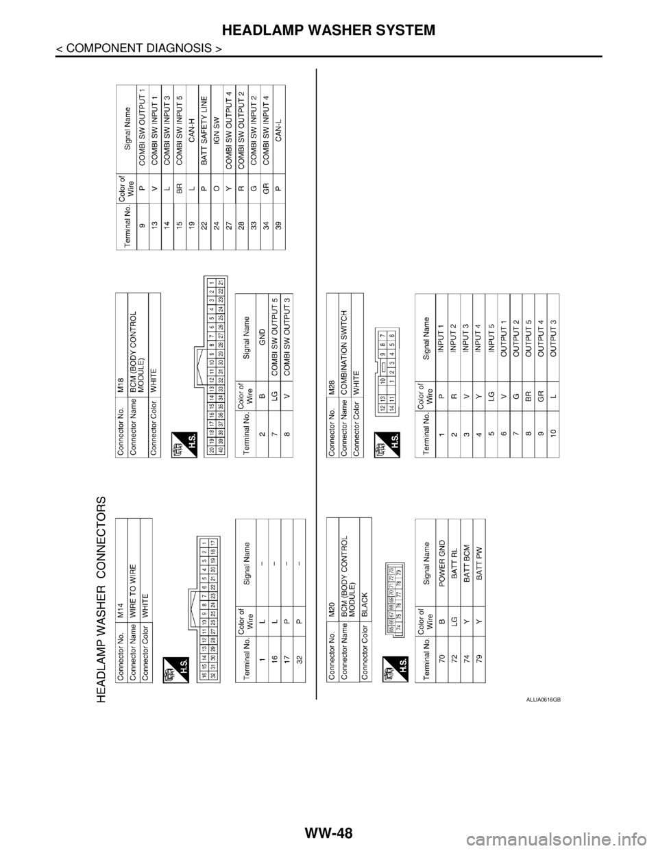
ALLIA0616GB
Page 5851 of 5883
HEADLAMP WASHER SYSTEM
WW-49
< COMPONENT DIAGNOSIS >
C
D
E
F
G
H
I
J
K
MA
B
WW
N
O
P
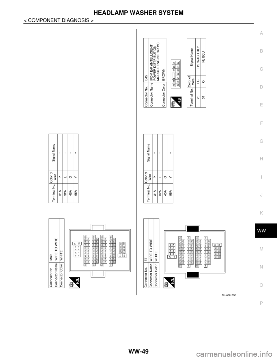
ALLIA0617GB