headlamp NISSAN TIIDA 2007 Service Repair Manual
[x] Cancel search | Manufacturer: NISSAN, Model Year: 2007, Model line: TIIDA, Model: NISSAN TIIDA 2007Pages: 5883, PDF Size: 78.95 MB
Page 5852 of 5883
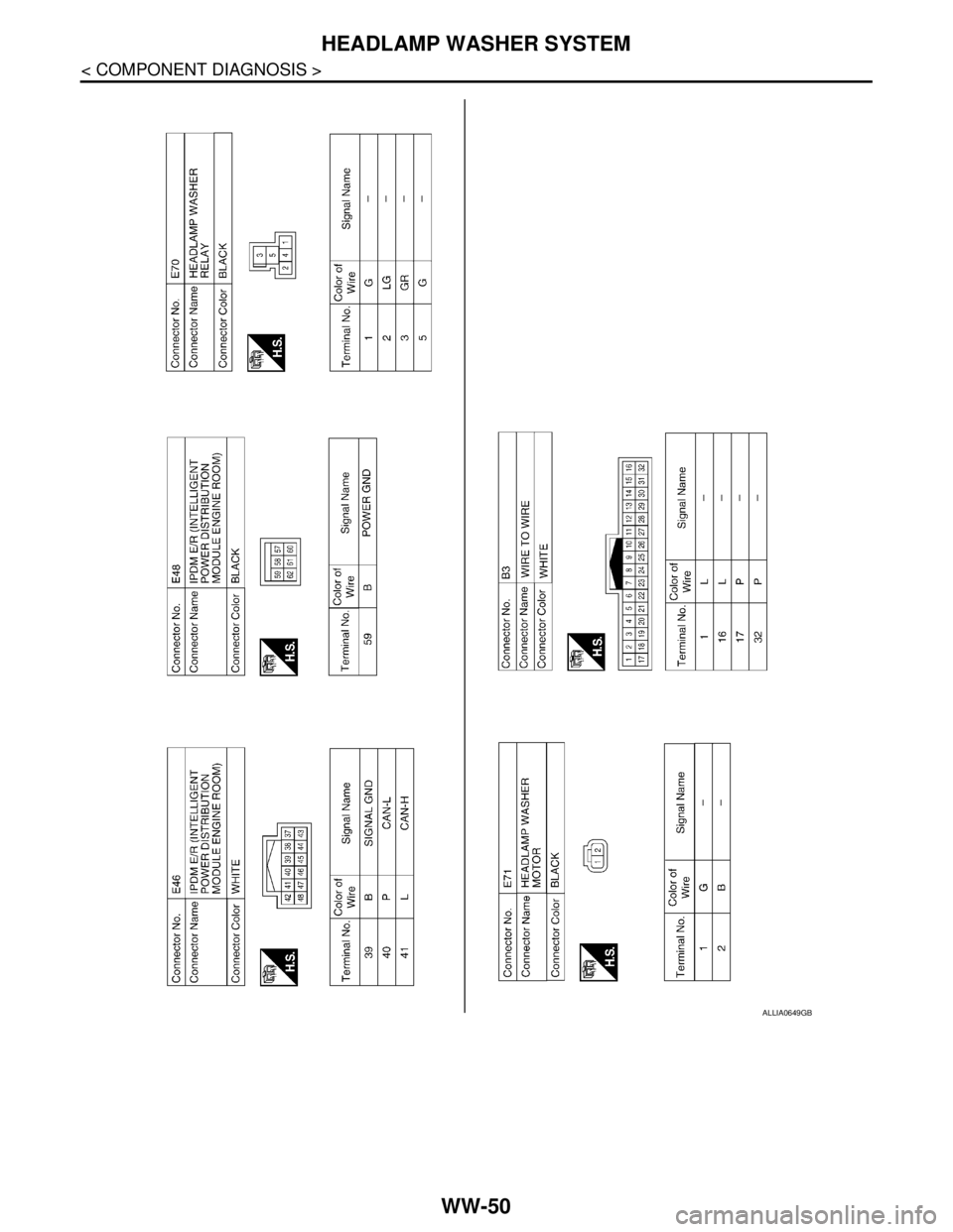
WW-50
< COMPONENT DIAGNOSIS >
HEADLAMP WASHER SYSTEM
ALLIA0649GB
Page 5854 of 5883

WW-52
< ECU DIAGNOSIS >
IPDM E/R (INTELLIGENT POWER DISTRIBUTION MODULE ENGINE ROOM)
IPDM E/R (INTELLIGENT POWER DISTRIBUTION MODULE ENGINE
ROOM)
Reference ValueINFOID:0000000001366636
VALUES ON THE DIAGNOSIS TOOL
TERMINAL LAYOUT
Refer to xxx.
PHYSICAL VALUES
Refer to xxx.
Fail SafeINFOID:0000000001366638
CAN communication control
When CAN communication with ECM and BCM is impossible, IPDM E/R performs fail-safe control. After CAN
communication recovers normally, it also returns to normal control.
If no CAN communication is available with BCM
Front wiper control
IPDM E/R detects the front wiper stop position with the front wiper auto stop signal.
When the front wiper auto stop signal is in the conditions listed below, IPDM E/R repeats a front wiper 10 sec-
onds operation and 20 seconds stop five times.
Monitor Item Condition Value/Status
HL WASHER REQIgnition switch ON, and low
beam headlamp is ONFront washer switch OFF Off
Front washer switch ON
(When headlamp washer is operat-
ing)On
FR WIP REQ Ignition switch ONFront wiper switch OFF STOP
Front wiper switch INT 1LOW
Front wiper switch LO Low
Front wiper switch HI Hi
WIP AUTO STOP Ignition switch ONFront wiper stop position STOP P
Any position other than front wiper
stop positionACT P
WIP PROT Ignition switch ONFront wiper operates normally Off
Front wiper stops at fail-safe oper-
ationBLOCK
IGN RLYIgnition switch OFF or ACC Off
Ignition switch ON On
IGN ON SWIgnition switch OFF or ACC Off
Ignition switch ON On
Control part Fail-safe in operation
Front wiper The status just before activation of fail-safe control is maintained until the ignition
switch is turned OFF while the front wiper is operating at LO or HI speed.
The front wiper is operated at LO speed until the ignition switch is turned OFF if the
fail-safe control is activated while the front wiper is set in the INT mode and the front
wiper motor is operating.
Headlamp washer Headlamp washer relay OFF
Page 5858 of 5883
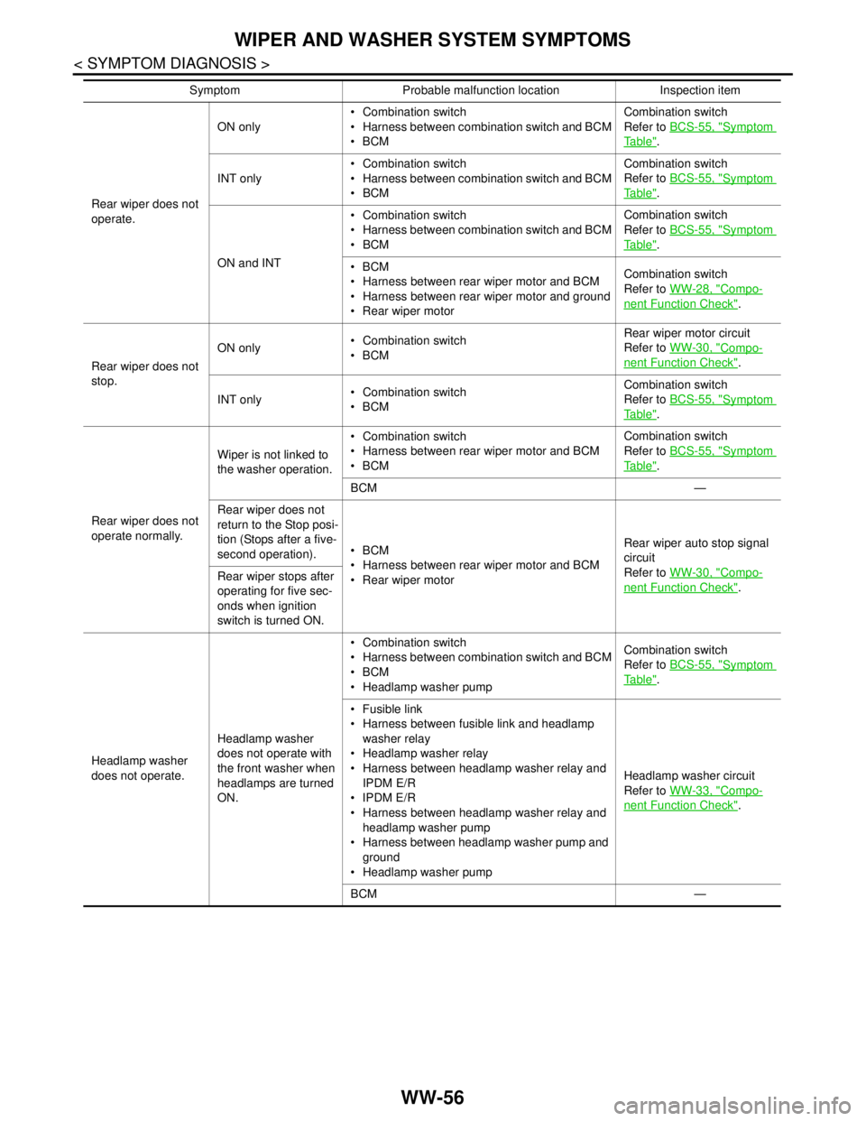
WW-56
< SYMPTOM DIAGNOSIS >
WIPER AND WASHER SYSTEM SYMPTOMS
Rear wiper does not
operate.ON only Combination switch
Harness between combination switch and BCM
BCMCombination switch
Refer to BCS-55, "
Symptom
Ta b l e".
INT only Combination switch
Harness between combination switch and BCM
BCMCombination switch
Refer to BCS-55, "
Symptom
Ta b l e".
ON and INT Combination switch
Harness between combination switch and BCM
BCMCombination switch
Refer to BCS-55, "
Symptom
Ta b l e".
BCM
Harness between rear wiper motor and BCM
Harness between rear wiper motor and ground
Rear wiper motorCombination switch
Refer to WW-28, "
Compo-
nent Function Check".
Rear wiper does not
stop.ON only Combination switch
BCMRear wiper motor circuit
Refer to WW-30, "
Compo-
nent Function Check".
INT only Combination switch
BCMCombination switch
Refer to BCS-55, "
Symptom
Ta b l e".
Rear wiper does not
operate normally.Wiper is not linked to
the washer operation. Combination switch
Harness between rear wiper motor and BCM
BCMCombination switch
Refer to BCS-55, "
Symptom
Ta b l e".
BCM —
Rear wiper does not
return to the Stop posi-
tion (Stops after a five-
second operation).BCM
Harness between rear wiper motor and BCM
Rear wiper motorRear wiper auto stop signal
circuit
Refer to WW-30, "
Compo-
nent Function Check". Rear wiper stops after
operating for five sec-
onds when ignition
switch is turned ON.
Headlamp washer
does not operate.Headlamp washer
does not operate with
the front washer when
headlamps are turned
ON. Combination switch
Harness between combination switch and BCM
BCM
Headlamp washer pumpCombination switch
Refer to BCS-55, "
Symptom
Ta b l e".
Fusible link
Harness between fusible link and headlamp
washer relay
Headlamp washer relay
Harness between headlamp washer relay and
IPDM E/R
IPDM E/R
Harness between headlamp washer relay and
headlamp washer pump
Harness between headlamp washer pump and
ground
Headlamp washer pumpHeadlamp washer circuit
Refer to WW-33, "
Compo-
nent Function Check".
BCM — Symptom Probable malfunction location Inspection item
Page 5862 of 5883
WW-60
< SYMPTOM DIAGNOSIS >
HEADLAMP WASHER DOES NOT OPERATE
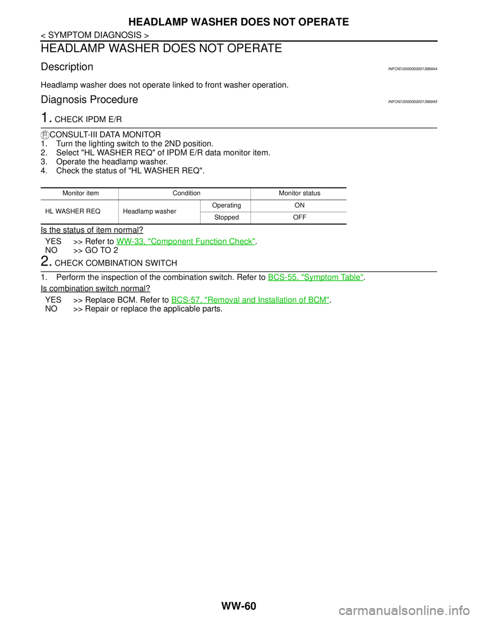
HEADLAMP WASHER DOES NOT OPERATE
DescriptionINFOID:0000000001366644
Headlamp washer does not operate linked to front washer operation.
Diagnosis ProcedureINFOID:0000000001366645
1. CHECK IPDM E/R
CONSULT-III DATA MONITOR
1. Turn the lighting switch to the 2ND position.
2. Select "HL WASHER REQ" of IPDM E/R data monitor item.
3. Operate the headlamp washer.
4. Check the status of "HL WASHER REQ".
Is the status of item normal?
YES >> Refer to WW-33, "Component Function Check".
NO >> GO TO 2
2. CHECK COMBINATION SWITCH
1. Perform the inspection of the combination switch. Refer to BCS-55, "
Symptom Table".
Is combination switch normal?
YES >> Replace BCM. Refer to BCS-57, "Removal and Installation of BCM".
NO >> Repair or replace the applicable parts.
Monitor item Condition Monitor status
HL WASHER REQ Headlamp washer Operating ON
Stopped OFF
Page 5864 of 5883
WW-62
< ON-VEHICLE REPAIR >
HEADLAMP WASHER NOZZLE AND TUBE
ON-VEHICLE REPAIR
HEADLAMP WASHER NOZZLE AND TUBE
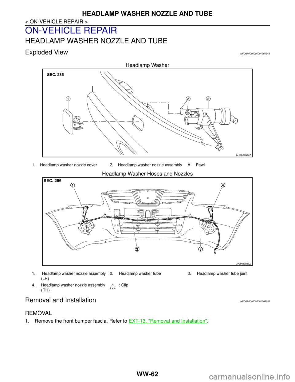
Exploded ViewINFOID:0000000001366648
Headlamp Washer
Headlamp Washer Hoses and Nozzles
Removal and InstallationINFOID:0000000001366650
REMOVAL
1. Remove the front bumper fascia. Refer to EXT-13, "Removal and Installation".
ALLIA0268ZZ
1. Headlamp washer nozzle cover 2. Headlamp washer nozzle assembly A. Pawl
JPLIA0292ZZ
1. Headlamp washer nozzle assembly
(LH)2. Headlamp washer tube 3. Headlamp washer tube joint
4. Headlamp washer nozzle assembly
(RH): Clip
Page 5865 of 5883
HEADLAMP WASHER NOZZLE AND TUBE
WW-63
< ON-VEHICLE REPAIR >
C
D
E
F
G
H
I
J
K
MA
B
WW
N
O
P
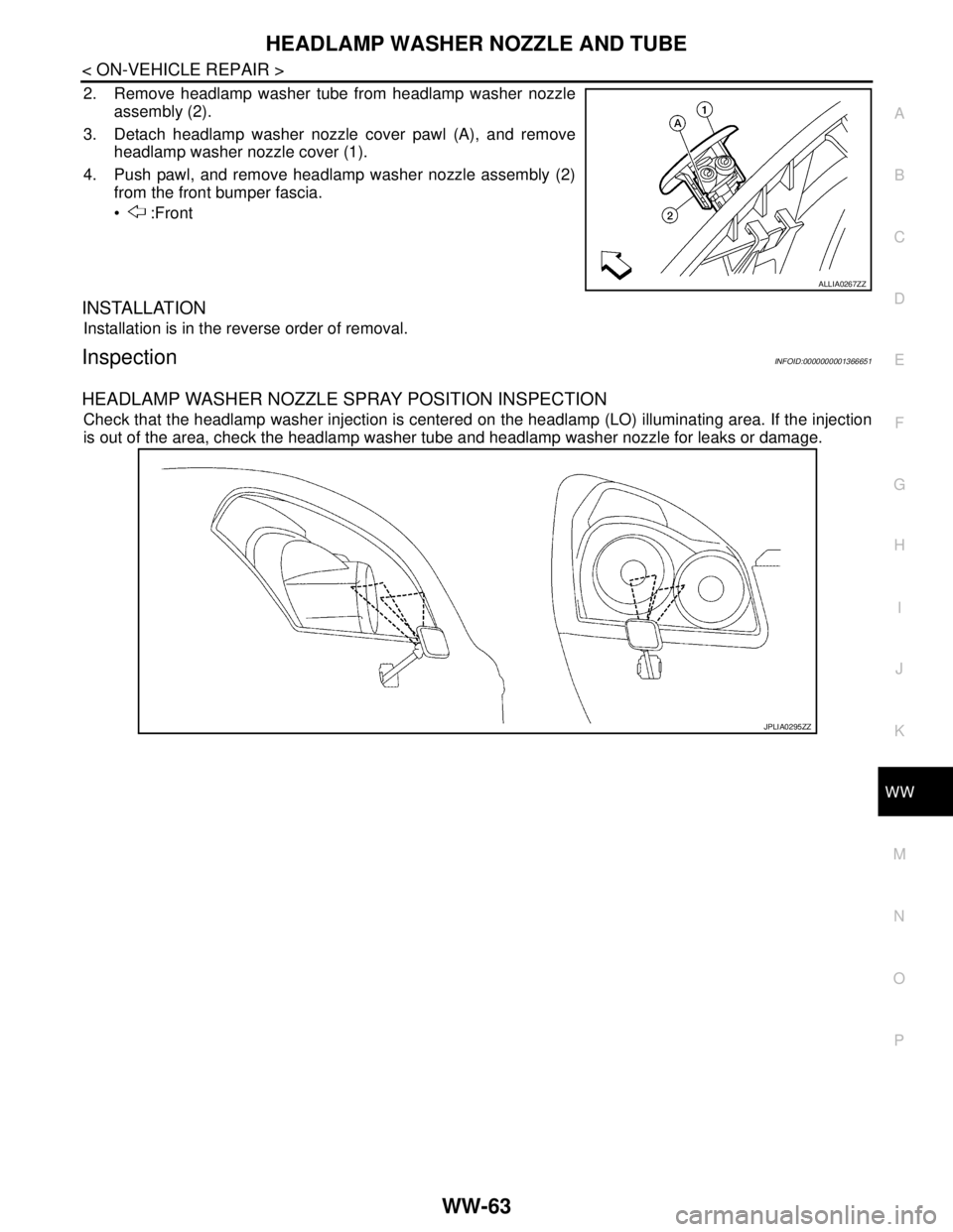
2. Remove headlamp washer tube from headlamp washer nozzle
assembly (2).
3. Detach headlamp washer nozzle cover pawl (A), and remove
headlamp washer nozzle cover (1).
4. Push pawl, and remove headlamp washer nozzle assembly (2)
from the front bumper fascia.
:Front
INSTALLATION
Installation is in the reverse order of removal.
InspectionINFOID:0000000001366651
HEADLAMP WASHER NOZZLE SPRAY POSITION INSPECTION
Check that the headlamp washer injection is centered on the headlamp (LO) illuminating area. If the injection
is out of the area, check the headlamp washer tube and headlamp washer nozzle for leaks or damage.
ALLIA0267ZZ
JPLIA0295ZZ
Page 5866 of 5883
WW-64
< ON-VEHICLE REPAIR >
WASHER TANK
WASHER TANK
Removal and InstallationINFOID:0000000001366653
REMOVAL
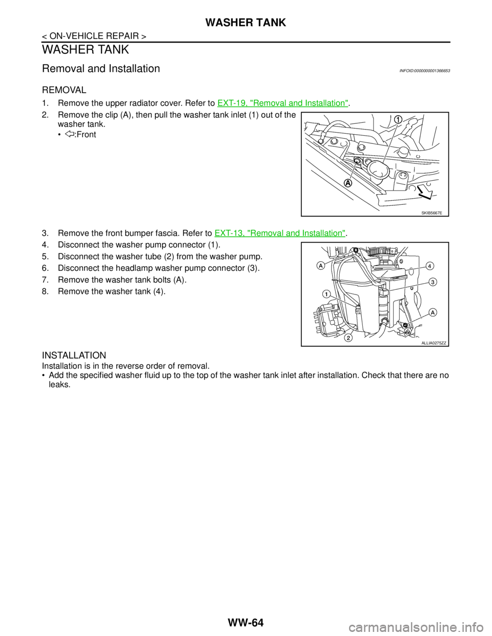
1. Remove the upper radiator cover. Refer to EXT-19, "Removal and Installation".
2. Remove the clip (A), then pull the washer tank inlet (1) out of the
washer tank.
:Front
3. Remove the front bumper fascia. Refer to EXT-13, "
Removal and Installation".
4. Disconnect the washer pump connector (1).
5. Disconnect the washer tube (2) from the washer pump.
6. Disconnect the headlamp washer pump connector (3).
7. Remove the washer tank bolts (A).
8. Remove the washer tank (4).
INSTALLATION
Installation is in the reverse order of removal.
Add the specified washer fluid up to the top of the washer tank inlet after installation. Check that there are no
leaks.
SKIB5667E
ALLIA0275ZZ
Page 5868 of 5883
WW-66
< ON-VEHICLE REPAIR >
HEADLAMP WASHER PUMP
HEADLAMP WASHER PUMP
Removal and InstallationINFOID:0000000001366657
REMOVAL
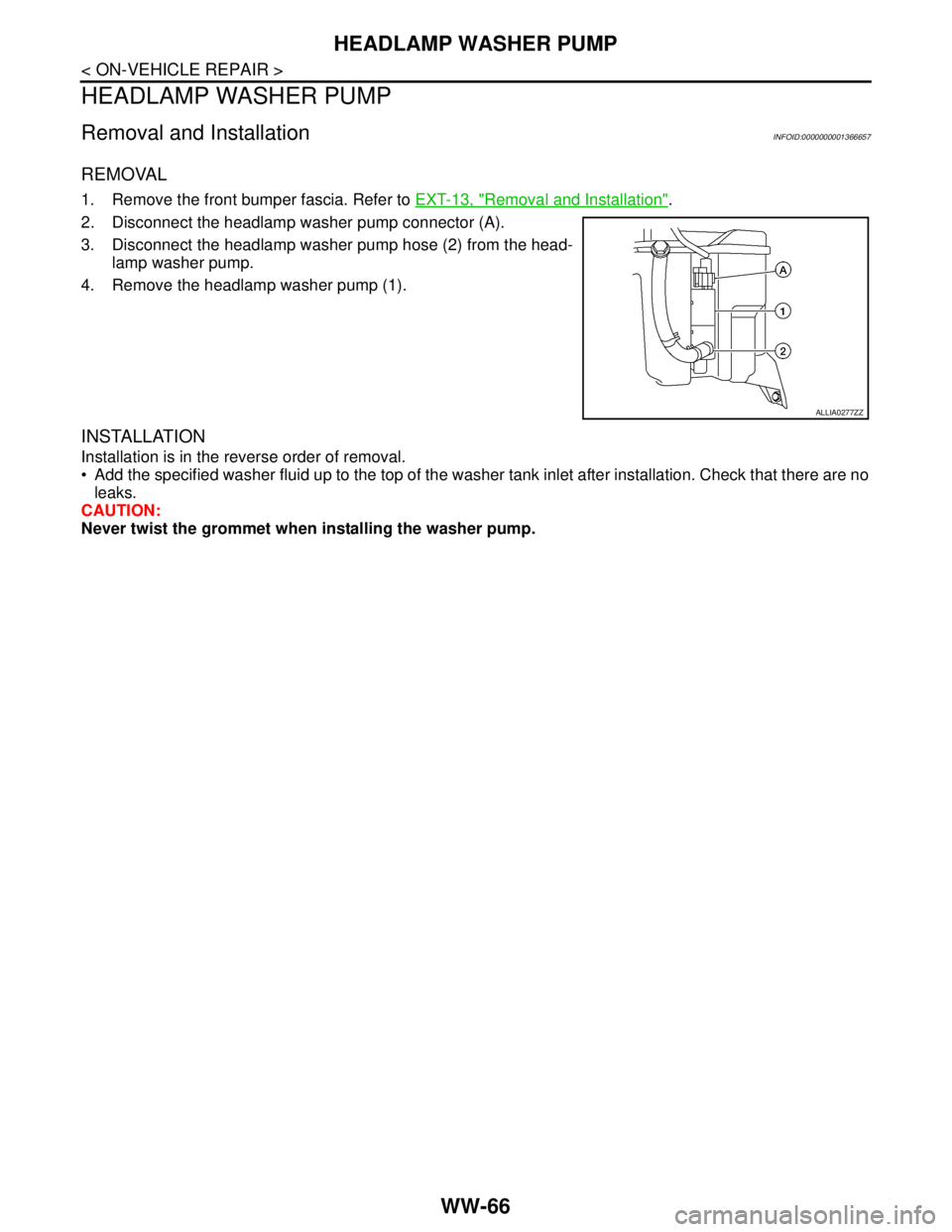
1. Remove the front bumper fascia. Refer to EXT-13, "Removal and Installation".
2. Disconnect the headlamp washer pump connector (A).
3. Disconnect the headlamp washer pump hose (2) from the head-
lamp washer pump.
4. Remove the headlamp washer pump (1).
INSTALLATION
Installation is in the reverse order of removal.
Add the specified washer fluid up to the top of the washer tank inlet after installation. Check that there are no
leaks.
CAUTION:
Never twist the grommet when installing the washer pump.
ALLIA0277ZZ