front cowl NISSAN TIIDA 2007 Service User Guide
[x] Cancel search | Manufacturer: NISSAN, Model Year: 2007, Model line: TIIDA, Model: NISSAN TIIDA 2007Pages: 5883, PDF Size: 78.95 MB
Page 2378 of 5883

PRECAUTIONS
EC-1029
< PRECAUTION >[MR18DE]
C
D
E
F
G
H
I
J
K
L
MA
EC
N
P O
PRECAUTION
PRECAUTIONS
Precaution for Supplemental Restraint System (SRS) "AIR BAG" and "SEAT BELT
PRE-TENSIONER"
INFOID:0000000001161999
The Supplemental Restraint System such as “AIR BAG” and “SEAT BELT PRE-TENSIONER”, used along
with a front seat belt, helps to reduce the risk or severity of injury to the driver and front passenger for certain
types of collision. This system includes seat belt switch inputs and dual stage front air bag modules. The SRS
system uses the seat belt switches to determine the front air bag deployment, and may only deploy one front
air bag, depending on the severity of a collision and whether the front occupants are belted or unbelted.
Information necessary to service the system safely is included in the SRC and SB section of this Service Man-
ual.
WARNING:
To avoid rendering the SRS inoperative, which could increase the risk of personal injury or death in
the event of a collision which would result in air bag inflation, all maintenance must be performed by
an authorized NISSAN/INFINITI dealer.
Improper maintenance, including incorrect removal and installation of the SRS, can lead to personal
injury caused by unintentional activation of the system. For removal of Spiral Cable and Air Bag
Module, see the SRC section.
Do not use electrical test equipment on any circuit related to the SRS unless instructed to in this
Service Manual. SRS wiring harnesses can be identified by yellow and/or orange harnesses or har-
ness connectors.
Precaution for Procedure without Cowl Top CoverINFOID:0000000001162000
When performing the procedure after removing cowl top cover, cover
the lower end of windshield with urethane, etc.
Precautions For Xenon Headlamp ServiceINFOID:0000000001679886
WARNING:
Comply with the following warnings to prevent any serious accident.
Disconnect the battery cable (negative terminal) or the power supply fuse before installing, remov-
ing, or touching the xenon headlamp (bulb included). The xenon headlamp contains high-voltage
generated parts.
Never work with wet hands.
Check the xenon headlamp ON-OFF status after assembling it to the vehicle. Never turn the xenon
headlamp ON in other conditions. Connect the power supply to the vehicle-side connector.
(Turning it ON outside the lamp case may cause fire or visual impairments.)
Never touch the bulb glass immediately after turning it OFF. It is extremely hot.
CAUTION:
Comply with the following cautions to prevent any error and malfunction.
Install the xenon bulb securely. (Insufficient bulb socket installation may melt the bulb, the connec-
tor, the housing, etc. by high-voltage leakage or corona discharge.)
Never perform HID circuit inspection with a tester.
Never touch the xenon bulb glass with hands. Never put oil and grease on it.
Dispose of the used xenon bulb after packing it in thick vinyl without breaking it.
Never wipe out dirt and contamination with organic solvent (thinner, gasoline, etc.).
PIIB3706J
Page 2642 of 5883

PRECAUTIONS
EC-1293
< PRECAUTION >[K9K]
C
D
E
F
G
H
I
J
K
L
MA
EC
N
P O
PRECAUTION
PRECAUTIONS
Precaution for Supplemental Restraint System (SRS) "AIR BAG" and "SEAT BELT
PRE-TENSIONER"
INFOID:0000000001706108
The Supplemental Restraint System such as “AIR BAG” and “SEAT BELT PRE-TENSIONER”, used along
with a front seat belt, helps to reduce the risk or severity of injury to the driver and front passenger for certain
types of collision. Information necessary to service the system safely is included in the SR and SB section of
this Service Manual.
WARNING:
To avoid rendering the SRS inoperative, which could increase the risk of personal injury or death in
the event of a collision which would result in air bag inflation, all maintenance must be performed by
an authorized NISSAN/INFINITI dealer.
Improper maintenance, including incorrect removal and installation of the SRS, can lead to personal
injury caused by unintentional activation of the system. For removal of Spiral Cable and Air Bag
Module, see the SR section.
Do not use electrical test equipment on any circuit related to the SRS unless instructed to in this
Service Manual. SRS wiring harnesses can be identified by yellow and/or orange harnesses or har-
ness connectors.
Precaution for Procedure without Cowl Top CoverINFOID:0000000001162744
When performing the procedure after removing cowl top cover, cover
the lower end of windshield with urethane, etc.
On Board Diagnostic (OBD) System of EngineINFOID:0000000001162745
The ECM has an on board diagnostic system. It will light up the malfunction indicator (MI) to warn the driver of
a malfunction causing emission deterioration.
CAUTION:
Be sure to turn the ignition switch OFF and disconnect the battery negative cable before any repair
or inspection work. The open/short circuit of related switches, sensors, solenoid valves, etc. will
cause the MI to light up.
Be sure to connect and lock the connectors securely after work. A loose (unlocked) connector will
cause the MI to light up due to the open circuit. (Be sure the connector is free from water, grease,
dirt, bent terminals, etc.)
Certain systems and components, especially those related to OBD, may use a new style slide-lock-
ing type harness connector. For description and how to disconnect, refer to XX-XX, "*****"
.
Be sure to route and secure the harnesses properly after work. The interference of the harness with
a bracket, etc. may cause the MI to light up due to the short circuit.
Be sure to connect rubber tubes properly after work. A misconnected or disconnected rubber tube
may cause the MI to light up due to the malfunction of the fuel system, etc.
Be sure to erase the unnecessary malfunction information (repairs completed) from the ECM before
returning the vehicle to the customer.
PIIB3706J
Page 2649 of 5883
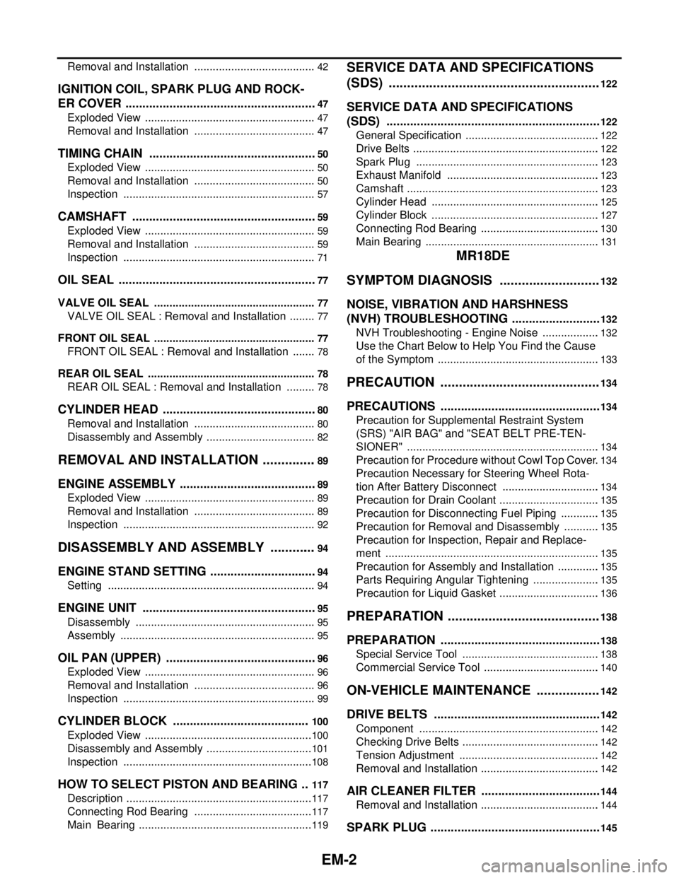
EM-2
Removal and Installation ........................................42
IGNITION COIL, SPARK PLUG AND ROCK-
ER COVER .........................................................
47
Exploded View ........................................................47
Removal and Installation ........................................47
TIMING CHAIN ..................................................50
Exploded View ........................................................50
Removal and Installation ........................................50
Inspection ...............................................................57
CAMSHAFT .......................................................59
Exploded View ........................................................59
Removal and Installation ........................................59
Inspection ...............................................................71
OIL SEAL ...........................................................77
VALVE OIL SEAL .....................................................77
VALVE OIL SEAL : Removal and Installation .........77
FRONT OIL SEAL .....................................................77
FRONT OIL SEAL : Removal and Installation ........78
REAR OIL SEAL .......................................................78
REAR OIL SEAL : Removal and Installation ..........78
CYLINDER HEAD ..............................................80
Removal and Installation ........................................80
Disassembly and Assembly ....................................82
REMOVAL AND INSTALLATION ...............89
ENGINE ASSEMBLY .........................................89
Exploded View ........................................................89
Removal and Installation ........................................89
Inspection ...............................................................92
DISASSEMBLY AND ASSEMBLY .............94
ENGINE STAND SETTING ................................94
Setting ....................................................................94
ENGINE UNIT ....................................................95
Disassembly ...........................................................95
Assembly ................................................................95
OIL PAN (UPPER) .............................................96
Exploded View ........................................................96
Removal and Installation ........................................96
Inspection ...............................................................99
CYLINDER BLOCK .........................................100
Exploded View .......................................................100
Disassembly and Assembly ...................................101
Inspection ..............................................................108
HOW TO SELECT PISTON AND BEARING ...117
Description .............................................................117
Connecting Rod Bearing .......................................117
Main Bearing .........................................................119
SERVICE DATA AND SPECIFICATIONS
(SDS) .........................................................
122
SERVICE DATA AND SPECIFICATIONS
(SDS) ................................................................
122
General Specification ............................................122
Drive Belts .............................................................122
Spark Plug ............................................................123
Exhaust Manifold ..................................................123
Camshaft ...............................................................123
Cylinder Head .......................................................125
Cylinder Block .......................................................127
Connecting Rod Bearing .......................................130
Main Bearing .........................................................131
MR18DE
SYMPTOM DIAGNOSIS ...........................
132
NOISE, VIBRATION AND HARSHNESS
(NVH) TROUBLESHOOTING ...........................
132
NVH Troubleshooting - Engine Noise ...................132
Use the Chart Below to Help You Find the Cause
of the Symptom .....................................................
133
PRECAUTION ...........................................134
PRECAUTIONS ................................................134
Precaution for Supplemental Restraint System
(SRS) "AIR BAG" and "SEAT BELT PRE-TEN-
SIONER" ...............................................................
134
Precaution for Procedure without Cowl Top Cover .134
Precaution Necessary for Steering Wheel Rota-
tion After Battery Disconnect ................................
134
Precaution for Drain Coolant .................................135
Precaution for Disconnecting Fuel Piping .............135
Precaution for Removal and Disassembly ............135
Precaution for Inspection, Repair and Replace-
ment ......................................................................
135
Precaution for Assembly and Installation ..............135
Parts Requiring Angular Tightening ......................135
Precaution for Liquid Gasket .................................136
PREPARATION .........................................138
PREPARATION ................................................138
Special Service Tool .............................................138
Commercial Service Tool ......................................140
ON-VEHICLE MAINTENANCE .................142
DRIVE BELTS ..................................................142
Component ...........................................................142
Checking Drive Belts .............................................142
Tension Adjustment ..............................................142
Removal and Installation .......................................142
AIR CLEANER FILTER ....................................144
Removal and Installation .......................................144
SPARK PLUG ...................................................145
Page 2650 of 5883
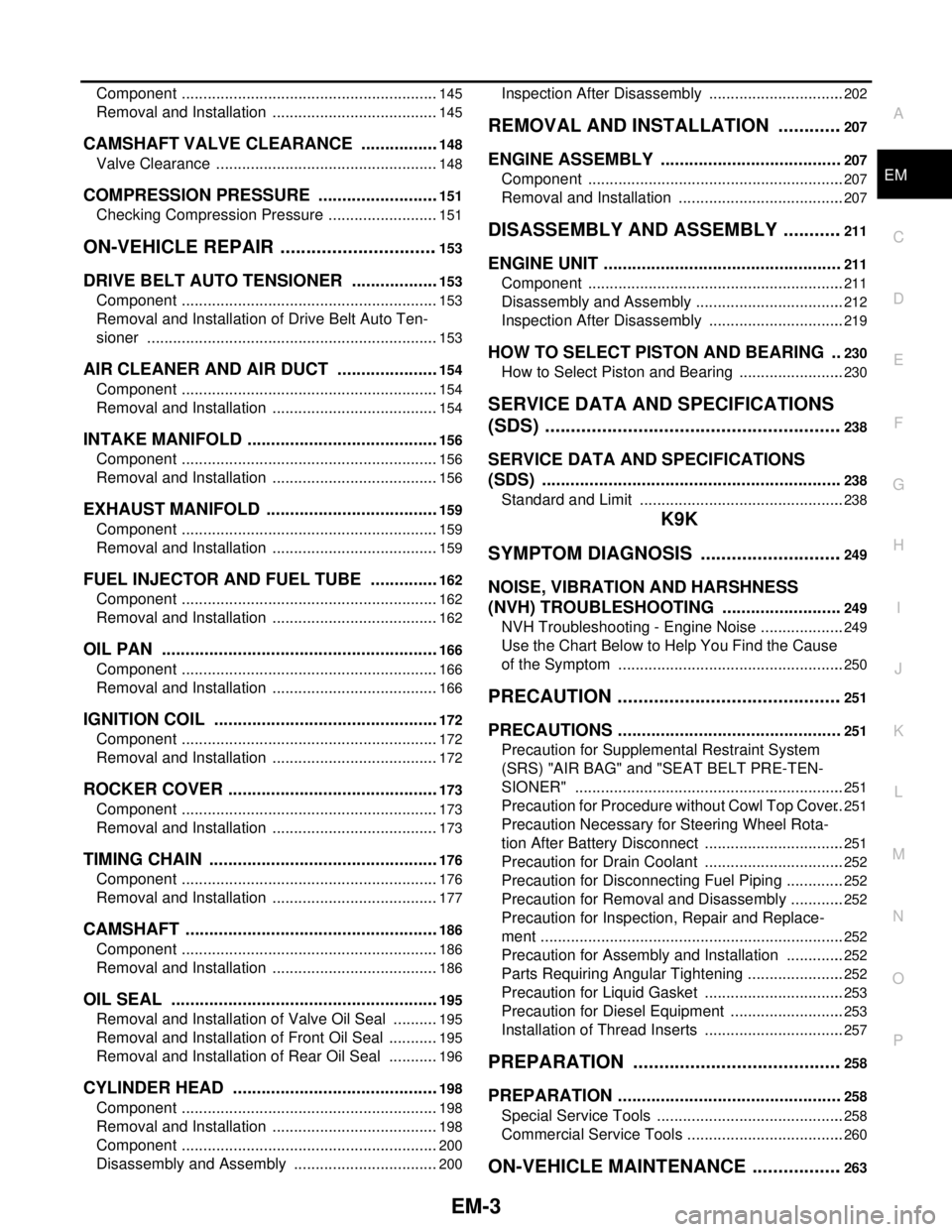
EM-3
C
D
E
F
G
H
I
J
K
L
M
EMA
N
O
P Component ............................................................
145
Removal and Installation .......................................145
CAMSHAFT VALVE CLEARANCE .................148
Valve Clearance ....................................................148
COMPRESSION PRESSURE ..........................151
Checking Compression Pressure ..........................151
ON-VEHICLE REPAIR ...............................153
DRIVE BELT AUTO TENSIONER ...................153
Component ............................................................153
Removal and Installation of Drive Belt Auto Ten-
sioner ....................................................................
153
AIR CLEANER AND AIR DUCT ......................154
Component ............................................................154
Removal and Installation .......................................154
INTAKE MANIFOLD .........................................156
Component ............................................................156
Removal and Installation .......................................156
EXHAUST MANIFOLD .....................................159
Component ............................................................159
Removal and Installation .......................................159
FUEL INJECTOR AND FUEL TUBE ...............162
Component ............................................................162
Removal and Installation .......................................162
OIL PAN ...........................................................166
Component ............................................................166
Removal and Installation .......................................166
IGNITION COIL ................................................172
Component ............................................................172
Removal and Installation .......................................172
ROCKER COVER .............................................173
Component ............................................................173
Removal and Installation .......................................173
TIMING CHAIN .................................................176
Component ............................................................176
Removal and Installation .......................................177
CAMSHAFT ......................................................186
Component ............................................................186
Removal and Installation .......................................186
OIL SEAL .........................................................195
Removal and Installation of Valve Oil Seal ...........195
Removal and Installation of Front Oil Seal ............195
Removal and Installation of Rear Oil Seal ............196
CYLINDER HEAD ............................................198
Component ............................................................198
Removal and Installation .......................................198
Component ............................................................200
Disassembly and Assembly ..................................200
Inspection After Disassembly ................................202
REMOVAL AND INSTALLATION .............207
ENGINE ASSEMBLY ......................................207
Component ............................................................207
Removal and Installation .......................................207
DISASSEMBLY AND ASSEMBLY ............211
ENGINE UNIT ..................................................211
Component ............................................................211
Disassembly and Assembly ...................................212
Inspection After Disassembly ................................219
HOW TO SELECT PISTON AND BEARING ..230
How to Select Piston and Bearing .........................230
SERVICE DATA AND SPECIFICATIONS
(SDS) ..........................................................
238
SERVICE DATA AND SPECIFICATIONS
(SDS) ...............................................................
238
Standard and Limit ................................................238
K9K
SYMPTOM DIAGNOSIS ............................
249
NOISE, VIBRATION AND HARSHNESS
(NVH) TROUBLESHOOTING .........................
249
NVH Troubleshooting - Engine Noise ....................249
Use the Chart Below to Help You Find the Cause
of the Symptom .....................................................
250
PRECAUTION ............................................251
PRECAUTIONS ...............................................251
Precaution for Supplemental Restraint System
(SRS) "AIR BAG" and "SEAT BELT PRE-TEN-
SIONER" ...............................................................
251
Precaution for Procedure without Cowl Top Cover ..251
Precaution Necessary for Steering Wheel Rota-
tion After Battery Disconnect .................................
251
Precaution for Drain Coolant .................................252
Precaution for Disconnecting Fuel Piping ..............252
Precaution for Removal and Disassembly .............252
Precaution for Inspection, Repair and Replace-
ment .......................................................................
252
Precaution for Assembly and Installation ..............252
Parts Requiring Angular Tightening .......................252
Precaution for Liquid Gasket .................................253
Precaution for Diesel Equipment ...........................253
Installation of Thread Inserts .................................257
PREPARATION .........................................258
PREPARATION ...............................................258
Special Service Tools ............................................258
Commercial Service Tools .....................................260
ON-VEHICLE MAINTENANCE ..................263
Page 2654 of 5883

PRECAUTIONS
EM-7
< PRECAUTION >[HR16DE]
C
D
E
F
G
H
I
J
K
L
MA
EM
N
P O
PRECAUTION
PRECAUTIONS
Precaution for Supplemental Restraint System (SRS) "AIR BAG" and "SEAT BELT
PRE-TENSIONER"
INFOID:0000000001527642
The Supplemental Restraint System such as “AIR BAG” and “SEAT BELT PRE-TENSIONER”, used along
with a front seat belt, helps to reduce the risk or severity of injury to the driver and front passenger for certain
types of collision. Information necessary to service the system safely is included in the SR and SB section of
this Service Manual.
WARNING:
• To avoid rendering the SRS inoperative, which could increase the risk of personal injury or death in
the event of a collision which would result in air bag inflation, all maintenance must be performed by
an authorized NISSAN/INFINITI dealer.
Improper maintenance, including incorrect removal and installation of the SRS, can lead to personal
injury caused by unintentional activation of the system. For removal of Spiral Cable and Air Bag
Module, see the SR section.
Do not use electrical test equipment on any circuit related to the SRS unless instructed to in this
Service Manual. SRS wiring harnesses can be identified by yellow and/or orange harnesses or har-
ness connectors.
Precaution for Procedure without Cowl Top CoverINFOID:0000000001527633
When performing the procedure after removing cowl top cover, cover
the lower end of windshield.
Precaution Necessary for Steering Wheel Rotation After Battery Disconnect
INFOID:0000000001527634
NOTE:
This Procedure is applied only to models with Intelligent Key system and NATS (NISSAN ANTI-THEFT SYS-
TEM).
Remove and install all control units after disconnecting both battery cables with the ignition knob in the
″LOCK″ position.
Always use CONSULT-II to perform self-diagnosis as a part of each function inspection after finishing work.
If DTC is detected, perform trouble diagnosis according to self-diagnostic results.
For models equipped with the Intelligent Key system and NATS, an electrically controlled steering lock mech-
anism is adopted on the key cylinder.
For this reason, if the battery is disconnected or if the battery is discharged, the steering wheel will lock and
steering wheel rotation will become impossible.
If steering wheel rotation is required when battery power is interrupted, follow the procedure below before
starting the repair operation.
OPERATION PROCEDURE
1. Connect both battery cables.
NOTE:
Supply power using jumper cables if battery is discharged.
2. Use the Intelligent Key or mechanical key to turn the ignition switch to the ″ACC″ position. At this time, the
steering lock will be released.
PIIB3706J
Page 2679 of 5883

EM-32
< ON-VEHICLE REPAIR >[HR16DE]
EXHAUST MANIFOLD
EXHAUST MANIFOLD
Exploded ViewINFOID:0000000001381400
Removal and InstallationINFOID:0000000001381401
REMOVAL
1. Remove the cowl. Refer to EXT-20, "Removal and Installation".
2. Remove the engine room cover.
3. Remove exhaust front tube. Refer to EX-5, "
Component".
4. Remove the harness bracket of heated oxygen sensor 1 from the cylinder head.
5. Remove exhaust manifold cover.
6. Remove the heated oxygen sensor 1.
1. Exhaust manifold cover 2. Exhaust manifold cover 3. Harness bracket
4. Heated oxygen sensor 1 5. Exhaust manifold stay 6. Exhaust manifold
7. Gasket 8. Stud bolt 9. Heat insulator
: Engine front
PBIC4750E
Page 2737 of 5883

EM-90
< REMOVAL AND INSTALLATION >[HR16DE]
ENGINE ASSEMBLY
If items or work required are not covered by the engine section, follow the procedures in the applica-
ble sections.
Always use the support point specified for lifting.
Use either 2-pole lift type or separate type lift as best you can. If board-on type is used for unavoid-
able reasons, support at the rear axle jacking point with a transmission jack or similar tool before
starting work, in preparation for the backward shift of center of gravity.
For supporting points for lifting and jacking point at rear axle, refer to GI-48, "
Garage Jack and
Safety Stand and 2-Pole Lift".
REMOVAL
Outline
Remove the engine and the transaxle assembly from the vehicle downward. Separate the engine and the tran-
saxle.
Preparation
1. Remove the hood assembly. Refer to DLK-214, "Removal and Installation".
2. Remove the cowl top cover and cowl top extension assembly. Refer to EXT-20, "
Removal and Installa-
tion".
3. Release fuel pressure. Refer to EC-377, "
Inspection" (EURO-OBD), EC-681, "Inspection" (WITHOUT
EURO-OBD).
4. Drain engine coolant from radiator. Refer to CO-11, "
Changing Engine Coolant".
CAUTION:
Perform this step when the engine is cold.
Never spill engine coolant on drive belt.
5. Drain the transmission fluid. Refer to TM-628, "
Draining" (M/T models), TM-171, "Changing A/T Fluid" (A/
T models).
6. Remove the following parts.
Engine undercover
Front road wheels and tires: Refer to WT-6, "
Rotation".
Front fender protector (RH and LH): Refer to EXT-22, "
Removal and Installation".
Battery and battery tray: Refer to PG-6, "
Removal and Installation".
Drive belt: Refer to EM-16, "
Removal and Installation".
Air duct and air cleaner case assembly: Refer to EM-27, "
Exploded View".
Radiator hose (upper and lower): Refer to CO-16, "
Component".
Disconnect cooling fan controller wiring harness.
Remove coolant reservoir tank.
Remove fan shroud and cooling fan assembly. Refer to CO-16, "
Component".
Engine Room LH
1. Disconnect all connections of engine harness around the engine mounting insulator (LH), and then tem-
porarily secure the engine harness into the engine side.
CAUTION:
Protect connectors using a resin bag against foreign materials.
2. Remove ground cable at transaxle side.
3. Disconnect fuel feed hose at engine side. Refer to EM-35, "
Exploded View".
4. Disconnect EVAP purge hose and brake booster vacuum hose.
5. Disconnect heater hoses, and install plugs them to prevent engine coolant from draining. Refer to CO-24,
"Exploded View".
6. Disconnect control linkage from transaxle. Refer to TM-189, "
Exploded View" (A/T), TM-630, "Exploded
View" (M/T).
7. Disconnect the clutch tube at transmission side. Refer to CL-12, "
Removal and Installation".
Engine Room RH
1. Remove ground cable between front cover and vehicle.
2. Remove generator and generator bracket; Refer to CHG-15, "
Removal and Installation".
3. Remove A/C compressor with piping connected from the engine. Temporarily secure it on the vehicle side
with a rope to avoid putting load on it. (with A/C models) Refer to HA-34, "
Removal and Installation of
Compressor - HR16DE".
Page 2781 of 5883

EM-134
< PRECAUTION >[MR18DE]
PRECAUTIONS
PRECAUTION
PRECAUTIONS
Precaution for Supplemental Restraint System (SRS) "AIR BAG" and "SEAT BELT
PRE-TENSIONER"
INFOID:0000000001527643
The Supplemental Restraint System such as “AIR BAG” and “SEAT BELT PRE-TENSIONER”, used along
with a front seat belt, helps to reduce the risk or severity of injury to the driver and front passenger for certain
types of collision. Information necessary to service the system safely is included in the SR and SB section of
this Service Manual.
WARNING:
To avoid rendering the SRS inoperative, which could increase the risk of personal injury or death in
the event of a collision which would result in air bag inflation, all maintenance must be performed by
an authorized NISSAN/INFINITI dealer.
Improper maintenance, including incorrect removal and installation of the SRS, can lead to personal
injury caused by unintentional activation of the system. For removal of Spiral Cable and Air Bag
Module, see the SR section.
Do not use electrical test equipment on any circuit related to the SRS unless instructed to in this
Service Manual. SRS wiring harnesses can be identified by yellow and/or orange harnesses or har-
ness connectors.
Precaution for Procedure without Cowl Top CoverINFOID:0000000001337763
When performing the procedure after removing cowl top cover, cover
the lower end of windshield.
Precaution Necessary for Steering Wheel Rotation After Battery Disconnect
INFOID:0000000001337764
NOTE:
This Procedure is applied only to models with Intelligent Key system and NATS (NISSAN ANTI-THEFT SYS-
TEM).
Remove and install all control units after disconnecting both battery cables with the ignition knob in the
″LOCK″ position.
Always use CONSULT-II to perform self-diagnosis as a part of each function inspection after finishing work.
If DTC is detected, perform trouble diagnosis according to self-diagnostic results.
For models equipped with the Intelligent Key system and NATS, an electrically controlled steering lock mech-
anism is adopted on the key cylinder.
For this reason, if the battery is disconnected or if the battery is discharged, the steering wheel will lock and
steering wheel rotation will become impossible.
If steering wheel rotation is required when battery power is interrupted, follow the procedure below before
starting the repair operation.
OPERATION PROCEDURE
1. Connect both battery cables.
NOTE:
Supply power using jumper cables if battery is discharged.
2. Use the Intelligent Key or mechanical key to turn the ignition switch to the ″ACC″ position. At this time, the
steering lock will be released.
PIIB3706J
Page 2855 of 5883

EM-208
< REMOVAL AND INSTALLATION >[MR18DE]
ENGINE ASSEMBLY
Always use the support point specified for lifting.
Use either 2-pole lift type or separate type lift as best you can. If board-on type is used for unavoid-
able reasons, support at the rear axle jacking point with a transmission jack or similar tool before
starting work, in preparation for the backward shift of center of gravity.
For supporting points for lifting and jacking point at rear axle, refer to GI-48, "
Garage Jack and
Safety Stand and 2-Pole Lift".
REMOVAL
Remove the engine and the transaxle assembly from the vehicle downward. Separate the engine and the tran-
saxle.
1. Remove engine undercover
2. Drain engine coolant from radiator. Refer to CO-35, "
Changing Engine Coolant".
CAUTION:
Perform this step when the engine is cold.
Do not spill engine coolant on drive belt.
3. Remove front fender protector (RH and LH); Refer to EXT-22, "
Removal and Installation".
4. Remove exhaust front tube; Refer to EX-10, "
Component".
5. Remove drive shafts (LH and RH) from steering knuckle. Refer to FA X - 7 , "
Removal and Installation".
6. Remove transaxle joint bolts which pierce at oil pan (upper) lower rear side. Refer to EM-207, "
Compo-
nent".
7. Remove rear torque rod (1).
8. Remove hood assembly. Refer to DLK-214, "
Removal and Installation".
9. Remove cowl top cover and cowl top extension assembly. Refer to EXT-20, "
Removal and Installation".
10. Release fuel pressure. Refer to EC-1035, "
Inspection".
11. Remove battery and battery tray; Refer to PG-6, "
Removal and Installation".
12. Remove drive belt; Refer to EM-142, "
Component".
13. Remove air duct and air cleaner case assembly; Refer to EM-154
.
14. Remove cooling fan assembly.
15. Remove radiator hose (upper and lower). Refer to CO-40, "
Component".
16. Disconnect all connections of engine harness around the engine mounting insulator (LH), and then tem-
porarily secure the engine harness into the engine side.
CAUTION:
Protect connectors using a resin bag to protect against foreign materials during the operation.
17. Disconnect fuel feed hose at engine side. Refer to EM-162, "
Component".
18. Disconnect heater hoses, and install plugs them to prevent engine coolant from draining. Refer to CO-47,
"Component".
19. Disconnect control cable from transaxle. Refer to TM-674, "
Exploded View".
20. Remove ground cable at transaxle side.
21. Remove ground cable between front cover and vehicle.
22. Remove generator. Refer to CHG-29, "
Removal and Installation".
23. Remove A/C compressor with piping connected from the engine. Temporarily secure it on the vehicle side
with a rope to avoid putting load on it. Refer to HA-32, "
Removal and Installation of Compressor -
MR18DE".
LBIA0460E
Page 2898 of 5883

PRECAUTIONS
EM-251
< PRECAUTION >[K9K]
C
D
E
F
G
H
I
J
K
L
MA
EM
N
P O
PRECAUTION
PRECAUTIONS
Precaution for Supplemental Restraint System (SRS) "AIR BAG" and "SEAT BELT
PRE-TENSIONER"
INFOID:0000000001516580
The Supplemental Restraint System such as “AIR BAG” and “SEAT BELT PRE-TENSIONER”, used along
with a front seat belt, helps to reduce the risk or severity of injury to the driver and front passenger for certain
types of collision. Information necessary to service the system safely is included in the SR and SB section of
this Service Manual.
WARNING:
To avoid rendering the SRS inoperative, which could increase the risk of personal injury or death in
the event of a collision which would result in air bag inflation, all maintenance must be performed by
an authorized NISSAN/INFINITI dealer.
Improper maintenance, including incorrect removal and installation of the SRS, can lead to personal
injury caused by unintentional activation of the system. For removal of Spiral Cable and Air Bag
Module, see the SR section.
Do not use electrical test equipment on any circuit related to the SRS unless instructed to in this
Service Manual. SRS wiring harnesses can be identified by yellow and/or orange harnesses or har-
ness connectors.
Precaution for Procedure without Cowl Top CoverINFOID:0000000001527630
When performing the procedure after removing cowl top cover, cover
the lower end of windshield with urethane, etc.
Precaution Necessary for Steering Wheel Rotation After Battery Disconnect
INFOID:0000000001527631
NOTE:
This Procedure is applied only to models with Intelligent Key system and NATS (NISSAN ANTI-THEFT SYS-
TEM).
Remove and install all control units after disconnecting both battery cables with the ignition knob in the
″LOCK″ position.
Always use CONSULT-III to perform self-diagnosis as a part of each function inspection after finishing work.
If DTC is detected, perform trouble diagnosis according to self-diagnostic results.
For models equipped with the Intelligent Key system and NATS, an electrically controlled steering lock mech-
anism is adopted on the key cylinder.
For this reason, if the battery is disconnected or if the battery is discharged, the steering wheel will lock and
steering wheel rotation will become impossible.
If steering wheel rotation is required when battery power is interrupted, follow the procedure below before
starting the repair operation.
OPERATION PROCEDURE
1. Connect both battery cables.
NOTE:
Supply power using jumper cables if battery is discharged.
2. Use the Intelligent Key or mechanical key to turn the ignition switch to the ″ACC″ position. At this time, the
steering lock will be released.
PIIB3706J