fuel consumption NISSAN TIIDA 2007 Service User Guide
[x] Cancel search | Manufacturer: NISSAN, Model Year: 2007, Model line: TIIDA, Model: NISSAN TIIDA 2007Pages: 5883, PDF Size: 78.95 MB
Page 2374 of 5883

ENGINE CONTROL SYSTEM
EC-1025
< SYMPTOM DIAGNOSIS >[MR18DE]
C
D
E
F
G
H
I
J
K
L
MA
EC
N
P O
1 - 6: The numbers refer to the order of inspection.
(continued on next page)
SYSTEM — ENGINE MECHANICAL & OTHER
Camshaft position sensor (PHASE) circuit 3 2EC-866
Vehicle speed signal circuit 2 3 3 3EC-878
ECM 22333333333EC-880
Intake valve timing control solenoid valve cir-
cuit32 13223 3EC-882
PNP switch circuit 3 3 3 3 3EC-942
Refrigerant pressure sensor circuit 2 3 3 4EC-988
Electrical load signal circuit 3EC-973
Air conditioner circuit 223333333 3 2HAC-92,
HAC-207
ABS actuator and electric unit (control unit) 4BRC-86
SYMPTOM
Reference
page
HARD/NO START/RESTART (EXCP. HA)
ENGINE STALL
HESITATION/SURGING/FLAT SPOT
SPARK KNOCK/DETONATION
LACK OF POWER/POOR ACCELERATION
HIGH IDLE/LOW IDLE
ROUGH IDLE/HUNTING
IDLING VIBRATION
SLOW/NO RETURN TO IDLE
OVERHEATS/WATER TEMPERATURE HIGH
EXCESSIVE FUEL CONSUMPTION
EXCESSIVE OIL CONSUMPTION
BATTERY DEAD (UNDER CHARGE)
Warranty symptom code AA AB AC AD AE AF AG AH AJ AK AL AM HA
Page 2375 of 5883

EC-1026
< SYMPTOM DIAGNOSIS >[MR18DE]
ENGINE CONTROL SYSTEM
SYMPTOM
Reference
page
HARD/NO START/RESTART (EXCP. HA)
ENGINE STALL
HESITATION/SURGING/FLAT SPOT
SPARK KNOCK/DETONATION
LACK OF POWER/POOR ACCELERATION
HIGH IDLE/LOW IDLE
ROUGH IDLE/HUNTING
IDLING VIBRATION
SLOW/NO RETURN TO IDLE
OVERHEATS/WATER TEMPERATURE HIGH
EXCESSIVE FUEL CONSUMPTION
EXCESSIVE OIL CONSUMPTION
BATTERY DEAD (UNDER CHARGE)
Warranty symptom code A
AAB AC AD AE AF AG AH AJ AK AL AM HA
Fuel Fuel tank
5
5FL-10
Fuel piping 555 55 5EM-162
Va p o r l o c k—
Valve deposit
5 555 55 5—
Poor fuel (Heavy weight gasoline,
Low octane)—
Air Air duct
55555 5EM-154
Air cleanerEM-154
Air leakage from air duct
(Mass air flow sensor — electric
throttle control actuator)
555 5EM-156
Electric throttle control actuator
Air leakage from intake manifold/
Collector/Gasket
Cranking Battery
111111
11PG-6
Generator circuitCHG-29
Starter circuit 3STR-24
Signal plate 6EM-219
PNP switch 4TM-665
Engine Cylinder head
55555 55 5EM-198
Cylinder head gasket 4 3
Cylinder block
66666 66 64
EM-200
Piston
Piston ring
Connecting rod
Bearing
Crankshaft
Va l v e
mecha-
nismTiming chain
55555 55 5EM-177
CamshaftEM-186
Intake valve timing controlEM-177
Intake valve
3EM-198
Exhaust valve
Page 2376 of 5883

ENGINE CONTROL SYSTEM
EC-1027
< SYMPTOM DIAGNOSIS >[MR18DE]
C
D
E
F
G
H
I
J
K
L
MA
EC
N
P O
1 - 6: The numbers refer to the order of inspection.Exhaust Exhaust manifold/Tube/Muffler/
Gasket
55555 55 5EX-5
, EX-9
Three way catalyst
Lubrica-
tionOil pan/Oil strainer/Oil pump/Oil
filter/Oil gallery/Oil cooler
55555 55 5EM-166
,
LU-18
, LU-
19
Oil level (Low)/Filthy oilLU-15
Cooling Radiator/Hose/Radiator filler cap
55555 55 45CO-40
Thermostat 5CO-45
Water pumpCO-44
Water galleryCO-28
Cooling fan
5CO-43
Coolant level (Low)/Contaminat-
ed coolantCO-35
NATS (NISSAN Anti-Theft System) 1 1SEC-7
SYMPTOM
Reference
page
HARD/NO START/RESTART (EXCP. HA)
ENGINE STALL
HESITATION/SURGING/FLAT SPOT
SPARK KNOCK/DETONATION
LACK OF POWER/POOR ACCELERATION
HIGH IDLE/LOW IDLE
ROUGH IDLE/HUNTING
IDLING VIBRATION
SLOW/NO RETURN TO IDLE
OVERHEATS/WATER TEMPERATURE HIGH
EXCESSIVE FUEL CONSUMPTION
EXCESSIVE OIL CONSUMPTION
BATTERY DEAD (UNDER CHARGE)
Warranty symptom code A
AAB AC AD AE AF AG AH AJ AK AL AM HA
Page 2630 of 5883

EXCESSIVE CONSUMPTION
EC-1281
< SYMPTOM DIAGNOSIS >[K9K]
C
D
E
F
G
H
I
J
K
L
MA
EC
N
P O
EXCESSIVE CONSUMPTION
DescriptionINFOID:0000000001162727
CHART 15:EXCESSIVE CONSUMPTION
Diagnosis ProcedureINFOID:0000000001162728
1.CHECK ECM POWER SUPPLY AND GROUND CIRCUIT
Check ECM power supply and ground circuit. Refer to EC-1106, "
Diagnosis Procedure".
Is the inspection result normal?
YES >> GO TO 2.
NO >> Repair or replace harness or connector.
2.CHECK WIRING HARNESS
Visually check the condition of the engine wiring harness.
Is the inspection result normal?
YES >> GO TO 3.
NO >> Repair or replace harness or connector.
3.CHECK AIR INTAKE SYSTEM
Check air intake system. Refer to EM-269, "
Removal and Installation".
Is the inspection result normal?
YES >> GO TO 4.
NO >> Repair or replace air intake system.
4.CHECK ELECTRIC THROTTLE CONTROL ACTUATOR
Check electric throttle control actuator. Refer to EC-1134, "
Diagnosis Procedure".
Is the inspection result normal?
YES >> GO TO 5.
NO >> Repair or replace.
5.CHECK MASS AIR FLOW SENSOR
Check mass air flow sensor. Refer to EC-1125, "
Component Inspection".
Is the inspection result normal?
YES >> GO TO 6.
NO >> Repair or replace.
6.CHECK TURBOCHARGER
Check that the turbocharger is working properly. Refer to EC-1195, "
Diagnosis Procedure".
Is the turbocharger correct?
Yes >> GO TO 7.
No >> Repair or replace.
7.CHECK ENGINE COOLANT TEMPERATURE SENSOR
Check engine coolant temperature sensor. Refer to EC-1133, "
Component Inspection".
Is the inspection result normal?
Yes >> GO TO 8.
No >> Repair or replace.
8.CHECK LOW PRESSURE CIRCUIT
Perform the TEST 1: LOW PRESSURE CIRCUIT CHECK. Refer to EC-1043, "
BASIC INSPECTION : Special
Repair Requirement (TEST 1: Low Pressure Fuel Supply System Check)".
>> GO TO 9.
9.CHECK INTERNAL FUEL TRANSFER PUMP
Page 2631 of 5883

EC-1282
< SYMPTOM DIAGNOSIS >[K9K]
EXCESSIVE CONSUMPTION
Perform the TEST 2: INTERNAL FUEL TRANSFER PUMP CHECK. Refer to EC-1044, "BASIC INSPECTION
: Special Repair Requirement (TEST 2: Internal Fuel Transfer Pump Check)".
>> GO TO 10.
10.CHECK HIGH PRESSURE SUPPLY PUMP (PRESSURE CONTROL VALVE)
Perform the TEST 3: HIGH PRESSURE SUPPLY PUMP (PRESSURE CONTROL VALVE). Refer to EC-1044,
"BASIC INSPECTION : Special Repair Requirement [TEST 3: High Pressure Supply Pump (Pressure Control
Valve) Check]".
>> GO TO 11.
11 .CHECK HIGH PRESSURE SUPPLY PUMP (VOLUMETRIC CONTROL VALVE)
Perform the TEST 4: HIGH PRESSURE SUPPLY PUMP (VOLUMETRIC CONTROL VALVE). Refer to EC-
1045, "BASIC INSPECTION : Special Repair Requirement [TEST 4: High Pressure Supply Pump (Volumetric
Control Valve) Check]".
>> GO TO 12.
12.CHECK RAIL HIGH PRESSURE CONTROL CIRCUIT
Perform the TEST 5: RAIL HIGH PRESSURE CONTROL CIRCUIT CHECK. Refer to EC-1048, "
BASIC
INSPECTION : Special Repair Requirement (TEST 5: Rail High Pressure Regulation Check)".
>> GO TO 13.
13.CHECK MAJOR LEAK IN FUEL INJECTOR/FUEL INJECTORS OPEN
Perform the TEST 6: MAJOR LEAK IN FUEL INJECTOR/FUEL INJECTORS OPEN. Refer to EC-1052,
"BASIC INSPECTION : Special Repair Requirement (TEST 6: Major Leak in Fuel Injectors/Fuel Injectors
Open)".
>> GO TO 14.
14.CHECK INCORRECT FUEL INJECTION QUANTITY
Perform the TEST 7: INCORRECT FUEL INJECTION QUANTITY. Refer to EC-1053, "
BASIC INSPECTION :
Special Repair Requirement (TEST 7: Incorrect Fuel Injection Quantity)".
>>INSPECTION END
Page 3773 of 5883

LAN
CAN COMMUNICATION SYSTEM
LAN-33
< FUNCTION DIAGNOSIS >[CAN]
C
D
E
F
G
H
I
J
K
L B A
O
P N
Check CAN system type from the vehicle shape and equipment.
CAN Communication Signal ChartINFOID:0000000001162801
Refer to LAN-21, "How to Use CAN Communication Signal Chart" for how to use CAN communication signal
chart.
NOTE:
Refer to LAN-27, "
Abbreviation List" for the abbreviations of the connecting units.
T: Transmit R: Receive
ALMIA0068GB
Signal name/Connecting unitECM
BCM
EPS
I-KEY
M&A
STRG
AV
ABS
TCM
IPDM-E
A/C compressor request signal TR
Accelerator pedal position signal T
R
*1R
ASCD CRUISE lamp signal T R
ASCD status signal T R
Closed throttle position signal T R
Cooling fan speed request signal TR
Engine coolant temperature signal T R R
Engine speed signal T R R R
R
*1R
Engine status signal T R R R
Fuel consumption monitor signal T R R
Glow indicator signal
*2TR
Malfunctioning indicator lamp signal (×2
*2)TR
Wide open throttle signal T R
A/C switch signal R T
Blower fan motor switch signal
*3RT
Page 4314 of 5883
MWI
METER SYSTEM
MWI-7
< FUNCTION DIAGNOSIS >
C
D
E
F
G
H
I
J
K
L
MB A
O
P
METER SYSTEM : Component DescriptionINFOID:0000000001537306
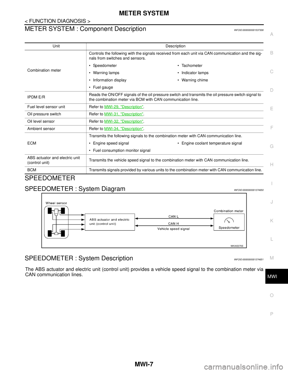
SPEEDOMETER
SPEEDOMETER : System DiagramINFOID:0000000001374650
SPEEDOMETER : System DescriptionINFOID:0000000001374651
The ABS actuator and electric unit (control unit) provides a vehicle speed signal to the combination meter via
CAN communication lines.
Unit Description
Combination meterControls the following with the signals received from each unit via CAN communication and the sig-
nals from switches and sensors.
Speedometer Tachometer
Warning lamps Indicator lamps
Information display Warning chime
Fuel gauge
IPDM E/RReads the ON/OFF signals of the oil pressure switch and transmits the oil pressure switch signal to
the combination meter via BCM with CAN communication line.
Fuel level sensor unit Refer to MWI-29, "
Description".
Oil pressure switch Refer to MWI-31, "
Description".
Oil level sensor Refer to MWI-32, "
Description".
Ambient sensor Refer to MWI-34, "
Description".
ECMTransmits the following signals to the combination meter with CAN communication line.
Engine speed signal Engine coolant temperature signal
Fuel consumption monitor signal
ABS actuator and electric unit
(control unit)Transmits the vehicle speed signal to the combination meter with CAN communication line.
BCM Transmits signals provided by various units to the combination meter with CAN communication line.
WKIA5370E
Page 4324 of 5883

MWI
METER SYSTEM
MWI-17
< FUNCTION DIAGNOSIS >
C
D
E
F
G
H
I
J
K
L
MB A
O
P
WARNING LAMPS/INDICATOR LAMPS : Component DescriptionINFOID:0000000001537300
INFORMATION DISPLAY
INFORMATION DISPLAY : System DiagramINFOID:0000000001374677
INFORMATION DISPLAY : System DescriptionINFOID:0000000001374678
FUNCTION
The information display can indicate the following items.
Engine oil change schedule
Engine oil level
Distance to empty
Journey time
Average fuel consumption
Average speed
Outside air temperature
ENGINE OIL CHANGE SCHEDULE
The remaining distance from the set engine oil change schedule is displayed.
OIL LEVEL
The combination meter judges the engine oil level based on the oil level sensor signal received from the oil
level sensor. If the oil level is sufficient, “Oil Good” is displayed for approximately 10 seconds. If the oil level is
low, “Oil Lo” blinks for approximately 30 seconds.
DISTANCE TO EMPTY
Unit Description
Combination meterTurns the oil pressure warning lamp ON/OFF according to the oil pressure switch signal received
from BCM by means of communication.
IPDM E/RReads the ON/OFF signals from the oil pressure switch and transmits the oil pressure switch signal
to the combination meter via BCM with the CAN communication line.
Oil pressure switch Refer to MWI-31, "
Description".
BCMTransmits the oil pressure switch signal received from IPDM E/R to the combination meter via CAN
communication.
AWNIA0163GB
Items Setting range Setting unit Description
Engine oil change
schedule0 – 30000 km
(0 – 18000 miles)1000 km
(500 miles)The remaining distance from the set distance is dis-
played for 5 seconds after the ignition switch is
turned ON.
Page 4325 of 5883

MWI-18
< FUNCTION DIAGNOSIS >
METER SYSTEM
The distance to empty indication provides the driver with an estimation of the distance that can be driven
before refueling. The distance to empty is calculated using signals from the fuel level sensor unit (fuel remain-
ing), ECM (fuel consumption) and vehicle speed signals from the ABS actuator and electric unit (control unit).
JOURNY TIME
The travel time since last reset is displayed.
AVERAGE FUEL CONSUMTION
Average fuel consumption indication is calculated using vehicle speed signals from the ABS actuator and elec-
tric unit (control unit) and fuel consumption information from the ECM.
AVERAGE SPEED
The average speed mode can be selected to display the average speed since last reset. The indications are
calculated using vehicle speed signals from the ABS actuator and electric unit (control unit).
OUTSIDE AIR TEMPERATURE
The combination meter indicates the outside air temperature calculated by the temperature signal received
from the ambient sensor.
The indicated temperature is not readily affected by engine heat. It changes only when one of the following
conditions is present.
The temperature detected by the ambient sensor is lower than the indicated temperature
The vehicle speed is greater than 20 km/h (13 MPH)
(This is to prevent the indicated temperature from being affected by engine heat during low-speed driving.)
The ignition switch has been turned to the OFF position for more than 3.5 hours. (The engine is cold.)
When the ambient air temperature falls below 3°C (37°F), the display starts flashing. Approximately 20 sec-
onds later, only “°C” flashes.
NOTE:
On vehicles equipped with auto A/C, the ambient sensor signal is shared with the front air control. The combi-
nation meter is notified of the signal sharing via the auto A/C sense circuit.
Page 4327 of 5883

MWI-20
< FUNCTION DIAGNOSIS >
METER SYSTEM
Unit Description
Combination meter Controls the information display according to the signal received from each unit.
Fuel level sensor unit Refer to MWI-29, "
Description".
ECMTransmits the following signals to the combination meter via CAN communication line.
Engine speed signal Fuel consumption monitor signal
ABS actuator and electric unit
(control unit)Transmits the vehicle speed signal to the combination meter via CAN communication line.
Ambient sensor Refer to MWI-34, "
Description".
Oil level sensor Refer to MWI-32, "
Description".