seats NISSAN TIIDA 2007 Service User Guide
[x] Cancel search | Manufacturer: NISSAN, Model Year: 2007, Model line: TIIDA, Model: NISSAN TIIDA 2007Pages: 5883, PDF Size: 78.95 MB
Page 2865 of 5883
![NISSAN TIIDA 2007 Service User Guide EM-218
< DISASSEMBLY AND ASSEMBLY >[MR18DE]
ENGINE UNIT
Apply new engine oil sufficiently to the cylinder bore, piston and crankshaft pin.
Match the cylinder position with the cylinder number (C) NISSAN TIIDA 2007 Service User Guide EM-218
< DISASSEMBLY AND ASSEMBLY >[MR18DE]
ENGINE UNIT
Apply new engine oil sufficiently to the cylinder bore, piston and crankshaft pin.
Match the cylinder position with the cylinder number (C)](/img/5/57395/w960_57395-2864.png)
EM-218
< DISASSEMBLY AND ASSEMBLY >[MR18DE]
ENGINE UNIT
Apply new engine oil sufficiently to the cylinder bore, piston and crankshaft pin.
Match the cylinder position with the cylinder number (C) on
connecting rod to install.
Install so that front mark (A) on the piston head faces the front
of engine.
Using a piston ring compressor [SST: EM03470000 (J-8037)]
(A) or suitable tool, install piston with the front mark on the pis-
ton head facing the front of the engine.
CAUTION:
Be careful not to damage the cylinder wall and crankshaft
pin, resulting from an interference of the connecting rod
big end.
22. Install connecting rod cap.
Match the stamped cylinder number marks (C) on connecting
rod with those on connecting rod cap to install.
23. Tighten connecting rod bolt with the following procedure:
CAUTION:
Make sure that there is no gap in the thrust surface (A) of
the joint between connecting rod (1) and connecting rod
bearing cap (2) and that these parts are in the correct
position. And then, tighten the connecting rod bolts.
If the connecting rod bolts are reused, measure the outer
diameter. Refer to EM-219, "
Inspection After Disassem-
bly".
24. Apply new engine oil to the threads and seats of connecting rod
bolts.
25. Tighten bolts in three steps
After tightening connecting rod bolt, make sure that crankshaft rotates smoothly.
Check the connecting rod side clearance. Refer to EM-219, "
Inspection After Disassembly".
26. Install oil pan (upper). Refer to EM-166
.
B : Oil hole
D : Big end diameter grade
E : Small end diameter grade
F : Front mark (connecting rod bearing cap)
PBIC3587J
PBIC3244J
A : Front mark (piston)
B : Oil hole
D : Big end diameter grade
E : Small end diameter grade
F : Front mark (connecting rod bearing cap)
PBIC3587J
Step 1 : 27.4 N·m (2.8 kg-m, 20 ft-lb)
Step 2 : 0 N·m (0 kg-m, 0 ft-lb)
Step 3 : 19.6 N·m (2.0 kg-m, 14 ft-lb)
PBIC3510J
Page 2956 of 5883
![NISSAN TIIDA 2007 Service User Guide CYLINDER HEAD
EM-309
< DISASSEMBLY AND ASSEMBLY >[K9K]
C
D
E
F
G
H
I
J
K
L
MA
EM
N
P O
1. Install new valves and grind them gently into their respective
seats. Clean all the parts thoroughly, mark the NISSAN TIIDA 2007 Service User Guide CYLINDER HEAD
EM-309
< DISASSEMBLY AND ASSEMBLY >[K9K]
C
D
E
F
G
H
I
J
K
L
MA
EM
N
P O
1. Install new valves and grind them gently into their respective
seats. Clean all the parts thoroughly, mark the](/img/5/57395/w960_57395-2955.png)
CYLINDER HEAD
EM-309
< DISASSEMBLY AND ASSEMBLY >[K9K]
C
D
E
F
G
H
I
J
K
L
MA
EM
N
P O
1. Install new valves and grind them gently into their respective
seats. Clean all the parts thoroughly, mark them for identification
purposes, then carry out the refitting operation.
Lubricate the inside of the valve guide.
It is imperative to fit the valve stem seals using valve seal drift
[KV113B0180 (Mot. 1511-01) (commercial service tool) or
equivalent tool].
NOTE:
Do not lubricate the valve stem seals before fitting them.
2. Place the valve in the cylinder head.
3. Place the barrel of valve seal drift [KV113B0180 (Mot. 1511-01)
(commercial service tool) or equivalent tool] over the valve stem
(the inner diameter of the barrel must be identical to the diame-
ter of the valve stem).
4. Keep the valve pressed against its seat.
5. Place the valve stem seal (not lubricated) over the tool barrel.
6. Push the valve stem seal past the tool barrel, then withdraw the
barrel.
MBIB0421E
MBIB0422E
MBIB0423E
MBIB0424E
Page 2959 of 5883
![NISSAN TIIDA 2007 Service User Guide EM-312
< DISASSEMBLY AND ASSEMBLY >[K9K]
CYLINDER HEAD
Va l v e S e a t
Measure the valve seats as follows.
Seat angle (α)
Contacting width (X)
Seat outer diameter (D):
Cylinder head seat re NISSAN TIIDA 2007 Service User Guide EM-312
< DISASSEMBLY AND ASSEMBLY >[K9K]
CYLINDER HEAD
Va l v e S e a t
Measure the valve seats as follows.
Seat angle (α)
Contacting width (X)
Seat outer diameter (D):
Cylinder head seat re](/img/5/57395/w960_57395-2958.png)
EM-312
< DISASSEMBLY AND ASSEMBLY >[K9K]
CYLINDER HEAD
Va l v e S e a t
Measure the valve seats as follows.
Seat angle (α)
Contacting width (X)
Seat outer diameter (D):
Cylinder head seat recess diameter (D)
Valve Guide Clearance
1. Measure diameter of valve stem with micrometer.
2. Measure inner diameter of valve guide with inside micrometer.
3. Calculate the valve guide clearance.
(Valve guide clearance) = (Valve guide inner diameter) – (Valve
stem diameter)
If it exceeds the limit, replace and/or valve guide.
Valve Spring
Measure the valve spring as follows.
Free height
Length under load
Full pressed height
Wire diameter
Inner diameter
Outer diameterIntake : Refer to EM-335, "
CylinderHead"
Exhaust : Refer to EM-335, "CylinderHead"
Intake : Refer to EM-335, "CylinderHead"
Exhaust : Refer to EM-335, "CylinderHead"
Intake : Refer to EM-335, "CylinderHead"
Exhaust : Refer to EM-335, "CylinderHead"
Intake : Refer to EM-335, "CylinderHead"
Exhaust : Refer to EM-335, "CylinderHead"
Intake : Refer to EM-335, "CylinderHead"
Exhaust : Refer to EM-335, "CylinderHead"
E1BIA0066ZZ
Intake : 0.020 - 0.050 mm (0.0008 - 0.0020 in)
Exhaust : 0.030 - 0.063 mm (0.0012 - 0.0025 in)
SEM938C
Intake and exhaust : Refer to EM-335, "CylinderHead"
Intake and exhaust : Refer to EM-335, "CylinderHead"
Intake and exhaust : Refer to EM-335, "CylinderHead"
Intake and exhaust : Refer to EM-335, "CylinderHead"
Intake and exhaust : Refer to EM-335, "CylinderHead"
SEM113
Page 3111 of 5883
SQUEAK AND RATTLE TROUBLE DIAGNOSIS
EXT-7
< ON-VEHICLE MAINTENANCE >
C
D
E
F
G
H
I
J
L
MA
B
EXT
N
O
P
4. A loose license plate or bracket
Most of these incidents can be repaired by adjusting, securing or insulating the item(s) or component(s) caus-
ing the noise.
SUNROOF/HEADLINING
Noises in the sunroof/headlining area can often be traced to one of the following:
1. Sunroof lid, rail, linkage or seals making a rattle or light knocking noise
2. Sun visor shaft shaking in the holder
3. Front or rear windshield touching headliner and squeaking
Again, pressing on the components to stop the noise while duplicating the conditions can isolate most of these
incidents. Repairs usually consist of insulating with felt cloth tape.
OVERHEAD CONSOLE (FRONT AND REAR)
Overhead console noises are often caused by the console panel clips not being engaged correctly. Most of
these incidents are repaired by pushing up on the console at the clip locations until the clips engage.
In addition look for:
1. Loose harness or harness connectors.
2. Front console map/reading lamp lens loose.
3. Loose screws at console attachment points.
SEATS
When isolating seat noise it's important to note the position the seat is in and the load placed on the seat when
the noise is present. These conditions should be duplicated when verifying and isolating the cause of the
noise.
Cause of seat noise include:
1. Headrest rods and holder
2. A squeak between the seat pad cushion and frame
3. The rear seatback lock and bracket
These noises can be isolated by moving or pressing on the suspected components while duplicating the con-
ditions under which the noise occurs. Most of these incidents can be repaired by repositioning the component
or applying urethane tape to the contact area.
UNDERHOOD
Some interior noise may be caused by components under the hood or on the engine wall. The noise is then
transmitted into the passenger compartment.
Causes of transmitted underhood noise include:
1. Any component installed on the engine wall
2. Components that pass through the engine wall
3. Engine wall mounts and connectors
4. Loose radiator pins
5. Hood bumpers out of adjustment
6. Hood striker out of adjustment
These noises can be difficult to isolate since they cannot be reached from the interior of the vehicle. The best
method is to secure, move or insulate one component at a time and test drive the vehicle. Also, engine RPM
or load can be changed to isolate the noise. Repairs can usually be made by moving, adjusting, securing, or
insulating the component causing the noise.
Page 3264 of 5883
SQUEAK AND RATTLE TROUBLE DIAGNOSES
GW-5
< SYMPTOM DIAGNOSIS >
C
D
E
F
G
H
I
J
L
MA
B
GW
N
O
P
2. Trunk lid striker out of adjustment
3. The trunk lid torsion bars knocking together
4. A loose license plate or bracket
Most of these incidents can be repaired by adjusting, securing or insulating the item(s) or component(s) caus-
ing the noise.
SUNROOF/HEADLINING
Noises in the sunroof/headlining area can often be traced to one of the following:
1. Sunroof lid, rail, linkage or seals making a rattle or light knocking noise
2. Sun visor shaft shaking in the holder
3. Front or rear windshield touching headliner and squeaking
Again, pressing on the components to stop the noise while duplicating the conditions can isolate most of these
incidents. Repairs usually consist of insulating with felt cloth tape.
OVERHEAD CONSOLE (FRONT AND REAR)
Overhead console noises are often caused by the console panel clips not being engaged correctly. Most of
these incidents are repaired by pushing up on the console at the clip locations until the clips engage.
In addition look for:
1. Loose harness or harness connectors.
2. Front console map/reading lamp lense loose.
3. Loose screws at console attachment points.
SEATS
When isolating seat noise it's important to note the position the seat is in and the load placed on the seat when
the noise is present. These conditions should be duplicated when verifying and isolating the cause of the
noise.
Cause of seat noise include:
1. Headrest rods and holder
2. A squeak between the seat pad cushion and frame
3. The rear seatback lock and bracket
These noises can be isolated by moving or pressing on the suspected components while duplicating the con-
ditions under which the noise occurs. Most of these incidents can be repaired by repositioning the component
or applying urethane tape to the contact area.
UNDERHOOD
Some interior noise may be caused by components under the hood or on the engine wall. The noise is then
transmitted into the passenger compartment.
Causes of transmitted underhood noise include:
1. Any component mounted to the engine wall
2. Components that pass through the engine wall
3. Engine wall mounts and connectors
4. Loose radiator mounting pins
5. Hood bumpers out of adjustment
6. Hood striker out of adjustment
These noises can be difficult to isolate since they cannot be reached from the interior of the vehicle. The best
method is to secure, move or insulate one component at a time and test drive the vehicle. Also, engine RPM
or load can be changed to isolate the noise. Repairs can usually be made by moving, adjusting, securing, or
insulating the component causing the noise.
Page 3689 of 5883

INT-10
< PREPARATION >
SQUEAK AND RATTLE TROUBLE DIAGNOSIS
Most of these incidents can be repaired by adjusting, securing or insulating the item(s) or component(s) caus-
ing the noise.
SUNROOF/HEADLINING
Noises in the sunroof/headlining area can often be traced to one of the following:
1. Sunroof lid, rail, linkage or seals making a rattle or light knocking noise
2. Sun visor shaft shaking in the holder
3. Front or rear windshield touching headliner and squeaking
Again, pressing on the components to stop the noise while duplicating the conditions can isolate most of these
incidents. Repairs usually consist of insulating with felt cloth tape.
OVERHEAD CONSOLE (FRONT AND REAR)
Overhead console noises are often caused by the console panel clips not being engaged correctly. Most of
these incidents are repaired by pushing up on the console at the clip locations until the clips engage.
In addition look for:
1. Loose harness or harness connectors.
2. Front console map/reading lamp lens loose.
3. Loose screws at console attachment points.
SEATS
When isolating seat noise it's important to note the position the seat is in and the load placed on the seat when
the noise is present. These conditions should be duplicated when verifying and isolating the cause of the
noise.
Cause of seat noise include:
1. Headrest rods and holder
2. A squeak between the seat pad cushion and frame
3. The rear seatback lock and bracket
These noises can be isolated by moving or pressing on the suspected components while duplicating the con-
ditions under which the noise occurs. Most of these incidents can be repaired by repositioning the component
or applying urethane tape to the contact area.
UNDERHOOD
Some interior noise may be caused by components under the hood or on the engine wall. The noise is then
transmitted into the passenger compartment.
Causes of transmitted underhood noise include:
1. Any component installed on the engine wall
2. Components that pass through the engine wall
3. Engine wall mounts and connectors
4. Loose radiator pins
5. Hood bumpers out of adjustment
6. Hood striker out of adjustment
These noises can be difficult to isolate since they cannot be reached from the interior of the vehicle. The best
method is to secure, move or insulate one component at a time and test drive the vehicle. Also, engine RPM
or load can be changed to isolate the noise. Repairs can usually be made by moving, adjusting, securing, or
insulating the component causing the noise.
Page 3722 of 5883
SQUEAK AND RATTLE TROUBLE DIAGNOSES
IP-7
< SERVICE INFORMATION >
C
D
E
F
G
H
I
K
L
MA
B
IP
N
O
P
Most of these incidents can be repaired by adjusting, securing or insulating the item(s) or component(s) caus-
ing the noise.
SUNROOF/HEADLINING
Noises in the sunroof/headlining area can often be traced to one of the following:
1. Sunroof lid, rail, linkage or seals making a rattle or light knocking noise
2. Sun visor shaft shaking in the holder
3. Front or rear windshield touching headliner and squeaking
Again, pressing on the components to stop the noise while duplicating the conditions can isolate most of these
incidents. Repairs usually consist of insulating with felt cloth tape.
OVERHEAD CONSOLE (FRONT AND REAR)
Overhead console noises are often caused by the console panel clips not being engaged correctly. Most of
these incidents are repaired by pushing up on the console at the clip locations until the clips engage.
In addition look for:
1. Loose harness or harness connectors.
2. Front console map/reading lamp lens loose.
3. Loose screws at console attachment points.
SEATS
When isolating seat noise it's important to note the position the seat is in and the load placed on the seat when
the noise is present. These conditions should be duplicated when verifying and isolating the cause of the
noise.
Cause of seat noise include:
1. Headrest rods and holder
2. A squeak between the seat pad cushion and frame
3. The rear seatback lock and bracket
These noises can be isolated by moving or pressing on the suspected components while duplicating the con-
ditions under which the noise occurs. Most of these incidents can be repaired by repositioning the component
or applying urethane tape to the contact area.
UNDERHOOD
Some interior noise may be caused by components under the hood or on the engine wall. The noise is then
transmitted into the passenger compartment.
Causes of transmitted underhood noise include:
1. Any component mounted to the engine wall
2. Components that pass through the engine wall
3. Engine wall mounts and connectors
4. Loose radiator mounting pins
5. Hood bumpers out of adjustment
6. Hood striker out of adjustment
These noises can be difficult to isolate since they cannot be reached from the interior of the vehicle. The best
method is to secure, move or insulate one component at a time and test drive the vehicle. Also, engine RPM
or load can be changed to isolate the noise. Repairs can usually be made by moving, adjusting, securing, or
insulating the component causing the noise.
Page 4561 of 5883
SQUEAK AND RATTLE TROUBLE DIAGNOSES
RF-27
< SYMPTOM DIAGNOSIS >
C
D
E
F
G
H
I
J
L
MA
B
RF
N
O
P
2. Trunk lid striker out of adjustment
3. The trunk lid torsion bars knocking together
4. A loose license plate or bracket
Most of these incidents can be repaired by adjusting, securing or insulating the item(s) or component(s) caus-
ing the noise.
SUNROOF/HEADLINING
Noises in the sunroof/headlining area can often be traced to one of the following:
1. Sunroof lid, rail, linkage or seals making a rattle or light knocking noise
2. Sun visor shaft shaking in the holder
3. Front or rear windshield touching headliner and squeaking
Again, pressing on the components to stop the noise while duplicating the conditions can isolate most of these
incidents. Repairs usually consist of insulating with felt cloth tape.
OVERHEAD CONSOLE (FRONT AND REAR)
Overhead console noises are often caused by the console panel clips not being engaged correctly. Most of
these incidents are repaired by pushing up on the console at the clip locations until the clips engage.
In addition look for:
1. Loose harness or harness connectors.
2. Front console map/reading lamp lens loose.
3. Loose screws at console attachment points.
SEATS
When isolating seat noise it's important to note the position the seat is in and the load placed on the seat when
the noise is present. These conditions should be duplicated when verifying and isolating the cause of the
noise.
Cause of seat noise include:
1. Headrest rods and holder
2. A squeak between the seat pad cushion and frame
3. The rear seatback lock and bracket
These noises can be isolated by moving or pressing on the suspected components while duplicating the con-
ditions under which the noise occurs. Most of these incidents can be repaired by repositioning the component
or applying urethane tape to the contact area.
UNDERHOOD
Some interior noise may be caused by components under the hood or on the engine wall. The noise is then
transmitted into the passenger compartment.
Causes of transmitted underhood noise include:
1. Any component installed on the engine wall
2. Components that pass through the engine wall
3. Engine wall mounts and connectors
4. Loose radiator pins
5. Hood bumpers out of adjustment
6. Hood striker out of adjustment
These noises can be difficult to isolate since they cannot be reached from the interior of the vehicle. The best
method is to secure, move or insulate one component at a time and test drive the vehicle. Also, engine RPM
or load can be changed to isolate the noise. Repairs can usually be made by moving, adjusting, securing, or
insulating the component causing the noise.
Page 4569 of 5883
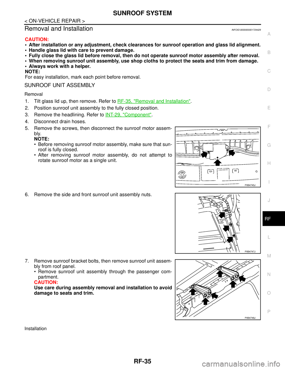
SUNROOF SYSTEM
RF-35
< ON-VEHICLE REPAIR >
C
D
E
F
G
H
I
J
L
MA
B
RF
N
O
P
Removal and InstallationINFOID:0000000001724429
CAUTION:
After installation or any adjustment, check clearances for sunroof operation and glass lid alignment.
Handle glass lid with care to prevent damage.
Fully close the glass lid before removal, then do not operate sunroof motor assembly after removal.
When removing sunroof unit assembly, use shop cloths to protect the seats and trim from damage.
Always work with a helper.
NOTE:
For easy installation, mark each point before removal.
SUNROOF UNIT ASSEMBLY
Removal
1. Tilt glass lid up, then remove. Refer to RF-35, "Removal and Installation".
2. Position sunroof unit assembly to the fully closed position.
3. Remove the headlining. Refer to INT-29, "
Component".
4. Disconnect drain hoses.
5. Remove the screws, then disconnect the sunroof motor assem-
bly.
NOTE:
Before removing sunroof motor assembly, make sure that sun-
roof is fully closed.
After removing sunroof motor assembly, do not attempt to
rotate sunroof motor as a single unit.
6. Remove the side and front sunroof unit assembly nuts.
7. Remove sunroof bracket bolts, then remove sunroof unit assem-
bly from roof panel.
Remove sunroof unit assembly through the passenger com-
partment.
CAUTION:
Use care during assembly removal and installation to avoid
damage to seats and trim.
Installation
PIIB4745J
PIIB4747J
PIIB4748J
Page 4587 of 5883

INSPECTION
SB-3
< BASIC INSPECTION >
C
D
E
F
G
I
J
K
L
MA
B
SB
N
O
P
BASIC INSPECTION
INSPECTION
Seat Belt InspectionINFOID:0000000001366781
AFTER A COLLISION
WARNING:
Inspect all seat belt assemblies including retractors and attaching hardware after any collision.
NISSAN recommends that all seat belt assemblies in use during a collision be replaced unless the col-
lision was minor and the belts show no damage and continue to operate properly. Failure to do so
could result in serious personal injury in an accident. Seat belt assemblies not in use during a colli-
sion should also be replaced if either damage or improper operation is noted. Seat belt pre-tensioner
should be replaced even if the seat belts are not in use during a frontal collision in which the air bags
are deployed.
Replace any seat belt assembly (including anchor bolts) if:
The seat belt was in use at the time of a collision (except for minor collisions and the belts, retractors and
buckles show no damage and continue to operate properly).
The seat belt was damaged in an accident. (i.e. torn webbing, bent retractor or guide, etc.)
The seat belt attaching point was damaged in an accident. Inspect the seat belt attaching area for damage
or distortion and repair as necessary before installing a new seat belt assembly.
Anchor bolts are deformed or worn out.
The seat belt pre-tensioner should be replaced even if the seat belts are not in use during a frontal collision
in which the air bags are deployed.
PRELIMINARY CHECKS
1. Check the seat belt warning lamp/chime for proper operation as follows:
a. Switch ignition ON. The seat belt warning lamp should illuminate. Also, the seat belt warning chime should
sound for about seven seconds.
b. Fasten driver's seat belt. The seat belt warning lamp should go out and the chime (if sounding) should
stop.
2. If the air bag warning lamp is blinking, conduct self-diagnosis using CONSULT-III, and air bag warning
lamp. Refer to SRC-11, "
SRS Operation Check".
3. Check that the seat belt retractor, seat belt anchor and buckle bolts are securely attached.
4. Check the shoulder seat belt guide and shoulder belt height adjuster for front seats. Make sure guide
swivels freely and that webbing lays flat and does not bind in guide. Make sure height adjuster operates
properly and holds securely.
5. Check retractor operation:
a. Fully extend the seat belt webbing and check for twists, tears or other damage.
b. Allow the seat belt to retract. Make sure that webbing returns smoothly and completely into the retractor. If
the seat belt does not return smoothly, wipe the inside of the loops with a clean paper cloth. Dirt build-up
in the loops of the upper anchors can cause the seat belts to retract slowly.
c. Fasten the seat belt. Check the seat belt returns smoothly and completely to the retractor. If the webbing
does not return smoothly, the cause may be an accumulation of dust or dirt. Use the “SEAT BELT TAPE
SET” and perform the following steps.
Inspect the front seat belt though-anchor
1. Pull the seat belt out to a length of 500 mm (19.69 in) or more.
2. Use a clip or other device to attach the seat belt at the center pillar webbing opening.
3. Pass a thin wire though the D-ring anchor webbing opening. Hold both ends of the wire and pull taut
while moving it up and down several times along the webbing opening surface to remove matter stuck
there.
4. Any dirt that cannot be removed with the wire can be removed by cleaning the opening with a clean
cloth.
5. Apply tape at the point where the webbing contacts the though-anchor webbing opening.
NOTE:
Apply the tape so that there is no looseness or wrinkling.
6. Remove the clip attaching the seat belt and check that the webbing returns smoothly.