tire type NISSAN TIIDA 2007 Service Repair Manual
[x] Cancel search | Manufacturer: NISSAN, Model Year: 2007, Model line: TIIDA, Model: NISSAN TIIDA 2007Pages: 5883, PDF Size: 78.95 MB
Page 49 of 5883
![NISSAN TIIDA 2007 Service Repair Manual AV-44
< FUNCTION DIAGNOSIS >[AUDIO WITH NAVIGATION]
DIAGNOSIS SYSTEM (NAVI CONTROL UNIT)
Select “SPEAKER TEST” to display the Speaker Diagnosis screen.
Press “START and NEXT” to generate a tes NISSAN TIIDA 2007 Service Repair Manual AV-44
< FUNCTION DIAGNOSIS >[AUDIO WITH NAVIGATION]
DIAGNOSIS SYSTEM (NAVI CONTROL UNIT)
Select “SPEAKER TEST” to display the Speaker Diagnosis screen.
Press “START and NEXT” to generate a tes](/img/5/57395/w960_57395-48.png)
AV-44
< FUNCTION DIAGNOSIS >[AUDIO WITH NAVIGATION]
DIAGNOSIS SYSTEM (NAVI CONTROL UNIT)
Select “SPEAKER TEST” to display the Speaker Diagnosis screen.
Press “START and NEXT” to generate a test tone in a speaker.
Press “Start” to generate a test tone in the next speaker. Press
“Stop” to stop the test tones.
NOTE:
The frequency of test tone emitted from each speaker is as follows.
Navigation
STEERING ANGLE ADJUSTMENT
The steering angle output value detected with the gyroscope is
adjusted.
SPEED CALIBRATION
During normal driving, distance error caused by tire wear and tire
pressure change is automatically adjusted for by the automatic dis-
tance correction function. This function, on the other hand, is for
immediate adjustment, in cases such as driving with tire chain fitted
on tires.
ERROR HISTORY
The diagnostic results of “Self-diagnosis” determine if any malfunction occurred between selecting “Self-diag-
nosis” and displaying “Self-diagnostic Results”.
The trouble diagnosis result will be judged normal if an error occurred before the ignition switch was turned
ON and does not occur again until “Self-diagnosis” is completed. Therefore, errors in the past which cannot be
found by “Self-diagnosis”, must be found by checking the “Error record”.
The error history shows the error occurrence frequency in past. The frequency of occurrence is displayed by 2
types: the count down type and the count up type. Select either type according to the error item.
In “Error History” of models with NAVI, time and place that the selected error last occurred are displayed. Be
careful about the following.
The correct date of occurrence may not be able to be displayed if there is a malfunction with the GPS
antenna circuit board in the NAVI control unit.
Place of the error occurrence is represented by the position of the current location mark at the time an error
occurred. If current location mark has deviated from the correct position, then the place of the error occur-
rence cannot be located correctly.Tweeter : 3 kHz
Front door speaker : 300 Hz
Rear door speaker : 1 kHz
SKIB4686E
SKIB3684E
SKIB3685E
Page 412 of 5883
![NISSAN TIIDA 2007 Service Repair Manual PRECAUTIONS
BRC-179
< PRECAUTION >[ESP/TCS/ABS]
C
D
E
G
H
I
J
K
L
MA
B
BRC
N
O
P
PRECAUTION
PRECAUTIONS
Precaution for Supplemental Restraint System (SRS) "AIR BAG" and "SEAT BELT
PRE-TENSIONER"
INFO NISSAN TIIDA 2007 Service Repair Manual PRECAUTIONS
BRC-179
< PRECAUTION >[ESP/TCS/ABS]
C
D
E
G
H
I
J
K
L
MA
B
BRC
N
O
P
PRECAUTION
PRECAUTIONS
Precaution for Supplemental Restraint System (SRS) "AIR BAG" and "SEAT BELT
PRE-TENSIONER"
INFO](/img/5/57395/w960_57395-411.png)
PRECAUTIONS
BRC-179
< PRECAUTION >[ESP/TCS/ABS]
C
D
E
G
H
I
J
K
L
MA
B
BRC
N
O
P
PRECAUTION
PRECAUTIONS
Precaution for Supplemental Restraint System (SRS) "AIR BAG" and "SEAT BELT
PRE-TENSIONER"
INFOID:0000000001691411
The Supplemental Restraint System such as “AIR BAG” and “SEAT BELT PRE-TENSIONER”, used along
with a front seat belt, helps to reduce the risk or severity of injury to the driver and front passenger for certain
types of collision. Information necessary to service the system safely is included in the SRS and SB section of
this Service Manual.
WARNING:
To avoid rendering the SRS inoperative, which could increase the risk of personal injury or death in
the event of a collision which would result in air bag inflation, all maintenance must be performed by
an authorized NISSAN/INFINITI dealer.
Improper maintenance, including incorrect removal and installation of the SRS, can lead to personal
injury caused by unintentional activation of the system. For removal of Spiral Cable and Air Bag
Module, see the SRS section.
Do not use electrical test equipment on any circuit related to the SRS unless instructed to in this
Service Manual. SRS wiring harnesses can be identified by yellow and/or orange harnesses or har-
ness connectors.
Precaution for Brake SystemINFOID:0000000001691412
Recommended fluid is Genuine NISSAN Fluid, DOT 3 or DOT 4 (US FMVSS No. 116).
Do not reuse drained brake fluid.
Be careful not to splash brake fluid on painted areas such as body. If brake fluid is splashed, wipe it off and
flush area with water immediately.
Do not use mineral oils such as gasoline or kerosene to clean. They will ruin rubber parts and cause
improper operation.
Using a flare nut torque wrench, securely tighten brake tube flare
nuts.
Brake system is an important safety part. If a brake fluid leak is
detected, always disassemble the affected part. If a malfunction is
detected, replace part with a new one.
Before working, turn ignition switch OFF and disconnect electrical
connectors of ABS actuator and electric unit (control unit) or bat-
tery negative terminals.
When installing brake piping, be sure to check torque.
After removing/installing any hydraulic parts of the brake or ESP
system (such as actuator and piping parts, etc), bleed air from the
system.
Precaution for Brake ControlINFOID:0000000001691413
During ESP/TCS/ABS operation, brake pedal lightly vibrates and a mechanical noise may be heard. This is
normal.
When starting engine, or just after starting vehicle, brake pedal may vibrate or motor operating noise may be
heard from engine room. This is a normal status of operation check.
Stopping distance may be longer than that of vehicles without ABS when vehicle drives on rough, gravel, or
snow-covered (fresh, deep snow) roads.
When an error is indicated by ABS or another warning lamp, collect all necessary information from the cus-
tomer (what symptoms are present under what conditions) and check for simple causes before starting diag-
nostic servicing. Besides the electrical system inspection, check booster operation, brake fluid level, and
fluid leaks.
If tire size and type are used in an improper combination, or brake pads are not Genuine NISSAN parts,
stopping distance or steering stability may deteriorate.
If there is a radio, antenna, or antenna lead-in wire (including wiring) near control module, ESP/TCS/ABS
function may have a malfunction or error.
If aftermarket parts (car stereo, CD player, etc.) have been installed, check for incidents such as harness
pinches, open circuits, and improper wiring.
SBR820BA
Page 2412 of 5883
![NISSAN TIIDA 2007 Service Repair Manual FUEL INJECTION CONTROL
EC-1063
< FUNCTION DIAGNOSIS >[K9K]
C
D
E
F
G
H
I
J
K
L
MA
EC
N
P O
FUEL INJECTION CONTROL
System DescriptionINFOID:0000000001162530
SYSTEM DESCRIPTION
The high pressure injecti NISSAN TIIDA 2007 Service Repair Manual FUEL INJECTION CONTROL
EC-1063
< FUNCTION DIAGNOSIS >[K9K]
C
D
E
F
G
H
I
J
K
L
MA
EC
N
P O
FUEL INJECTION CONTROL
System DescriptionINFOID:0000000001162530
SYSTEM DESCRIPTION
The high pressure injecti](/img/5/57395/w960_57395-2411.png)
FUEL INJECTION CONTROL
EC-1063
< FUNCTION DIAGNOSIS >[K9K]
C
D
E
F
G
H
I
J
K
L
MA
EC
N
P O
FUEL INJECTION CONTROL
System DescriptionINFOID:0000000001162530
SYSTEM DESCRIPTION
The high pressure injection system is designed to deliver a precise quantity of diesel fuel to the engine at a set
moment. The Siemens VDO piezo Common Rail system used on the K9K Step 2 engine is a second genera-
tion Common Rail injection system. Fuel pressure in the rail can reach a maximum of 1,600 bar. It uses fuel
injectors controlled by piezoelectric actuators. The fuel is pressurised by means of a high pressure pump then
sent to a rail which supplies the four fuel injectors.
The circuit comprises two subsystems, which are distinguished by the fuel pressure level:
- the low pressure circuit comprises the tank, the diesel fuel filter, the transfer pump and the fuel injector return
lines,
- the high-pressure circuit comprises the high-pressure (HP) pump, the rail, the fuel injectors and the high-
pressure (HP) pipes.
Finally, there are a number of control sensors and actuators which enable the entire system to be controlled
and monitored.
The system comprises:
- Priming bulb
- Fuel filter
- High pressure supply pump
- Fuel rail
- Fuel rail pressure sensor
- Fuel injector
- Fuel pump temperature sensor
- Engine coolant temperature sensor
- Camshaft position sensor
- Crankshaft position sensor
- Turbocharger boost sensor
- EGR volume control valve control position sensor
- EGR volume control valve
- Barometric pressure sensor (built in ECM)
- Mass air flow sensor
- Intake air temperature sensor
- Electric throttle control actuator
High Pressure Supply Pump
The high pressure supply pump consists of the following components:
Internal fuel transfer pump:
- This pump is a vane-type rotary pump. It draws in fuel from the fuel tank through a fuel filter and supplies the
high pressure pump with fuel.
Volumetric control valve:
- This solenoid valve regulates the flow of fuel entering the high pressure pump and enables an optimum
quantity of fuel to be pressurised according to operating phase; this improves the output of the high pressure
supply pump and thereby the output of the engine as well.
High pressure pump:
- This pump is a 3-piston radial pump, it generates the required pressure in the rail.
Pressure control valve:
- This solenoid valve regulates the output pressure of the high pressure pump.
Fuel Injector (Piezo Type)
CAUTION:
The fuel injector voltage is very high (much higher than that of conventional fuel injectors). This volt-
age can be as much as 150 V.
The piezo fuel injectors enable rapid, precise metering of the quantity of fuel injected, with excellent injection
process repetitivity.
The piezo actuator operates like a capacitor. To control the fuel injector, the computer sends, at the correct
time, a quantity of energy which is sufficient to enable the actuator to deform and the fuel injector to open.
During the injection period, the piezo actuator stores this energy.
At the end of the injection period, the computer recovers the energy sent at the start of the control operation.
The piezo actuator discharges and returns to its original shape. The fuel injector closes. To improve output, the
Page 2737 of 5883
![NISSAN TIIDA 2007 Service Repair Manual EM-90
< REMOVAL AND INSTALLATION >[HR16DE]
ENGINE ASSEMBLY
If items or work required are not covered by the engine section, follow the procedures in the applica-
ble sections.
Always use the suppo NISSAN TIIDA 2007 Service Repair Manual EM-90
< REMOVAL AND INSTALLATION >[HR16DE]
ENGINE ASSEMBLY
If items or work required are not covered by the engine section, follow the procedures in the applica-
ble sections.
Always use the suppo](/img/5/57395/w960_57395-2736.png)
EM-90
< REMOVAL AND INSTALLATION >[HR16DE]
ENGINE ASSEMBLY
If items or work required are not covered by the engine section, follow the procedures in the applica-
ble sections.
Always use the support point specified for lifting.
Use either 2-pole lift type or separate type lift as best you can. If board-on type is used for unavoid-
able reasons, support at the rear axle jacking point with a transmission jack or similar tool before
starting work, in preparation for the backward shift of center of gravity.
For supporting points for lifting and jacking point at rear axle, refer to GI-48, "
Garage Jack and
Safety Stand and 2-Pole Lift".
REMOVAL
Outline
Remove the engine and the transaxle assembly from the vehicle downward. Separate the engine and the tran-
saxle.
Preparation
1. Remove the hood assembly. Refer to DLK-214, "Removal and Installation".
2. Remove the cowl top cover and cowl top extension assembly. Refer to EXT-20, "
Removal and Installa-
tion".
3. Release fuel pressure. Refer to EC-377, "
Inspection" (EURO-OBD), EC-681, "Inspection" (WITHOUT
EURO-OBD).
4. Drain engine coolant from radiator. Refer to CO-11, "
Changing Engine Coolant".
CAUTION:
Perform this step when the engine is cold.
Never spill engine coolant on drive belt.
5. Drain the transmission fluid. Refer to TM-628, "
Draining" (M/T models), TM-171, "Changing A/T Fluid" (A/
T models).
6. Remove the following parts.
Engine undercover
Front road wheels and tires: Refer to WT-6, "
Rotation".
Front fender protector (RH and LH): Refer to EXT-22, "
Removal and Installation".
Battery and battery tray: Refer to PG-6, "
Removal and Installation".
Drive belt: Refer to EM-16, "
Removal and Installation".
Air duct and air cleaner case assembly: Refer to EM-27, "
Exploded View".
Radiator hose (upper and lower): Refer to CO-16, "
Component".
Disconnect cooling fan controller wiring harness.
Remove coolant reservoir tank.
Remove fan shroud and cooling fan assembly. Refer to CO-16, "
Component".
Engine Room LH
1. Disconnect all connections of engine harness around the engine mounting insulator (LH), and then tem-
porarily secure the engine harness into the engine side.
CAUTION:
Protect connectors using a resin bag against foreign materials.
2. Remove ground cable at transaxle side.
3. Disconnect fuel feed hose at engine side. Refer to EM-35, "
Exploded View".
4. Disconnect EVAP purge hose and brake booster vacuum hose.
5. Disconnect heater hoses, and install plugs them to prevent engine coolant from draining. Refer to CO-24,
"Exploded View".
6. Disconnect control linkage from transaxle. Refer to TM-189, "
Exploded View" (A/T), TM-630, "Exploded
View" (M/T).
7. Disconnect the clutch tube at transmission side. Refer to CL-12, "
Removal and Installation".
Engine Room RH
1. Remove ground cable between front cover and vehicle.
2. Remove generator and generator bracket; Refer to CHG-15, "
Removal and Installation".
3. Remove A/C compressor with piping connected from the engine. Temporarily secure it on the vehicle side
with a rope to avoid putting load on it. (with A/C models) Refer to HA-34, "
Removal and Installation of
Compressor - HR16DE".
Page 2885 of 5883
![NISSAN TIIDA 2007 Service Repair Manual EM-238
< SERVICE DATA AND SPECIFICATIONS (SDS) [MR18DE]
SERVICE DATA AND SPECIFICATIONS (SDS)
SERVICE DATA AND SPECIFICATIONS (SDS)
SERVICE DATA AND SPECIFICATIONS (SDS)
Standard and LimitINFOID:00000 NISSAN TIIDA 2007 Service Repair Manual EM-238
< SERVICE DATA AND SPECIFICATIONS (SDS) [MR18DE]
SERVICE DATA AND SPECIFICATIONS (SDS)
SERVICE DATA AND SPECIFICATIONS (SDS)
SERVICE DATA AND SPECIFICATIONS (SDS)
Standard and LimitINFOID:00000](/img/5/57395/w960_57395-2884.png)
EM-238
< SERVICE DATA AND SPECIFICATIONS (SDS) [MR18DE]
SERVICE DATA AND SPECIFICATIONS (SDS)
SERVICE DATA AND SPECIFICATIONS (SDS)
SERVICE DATA AND SPECIFICATIONS (SDS)
Standard and LimitINFOID:0000000001337815
GENERAL SPECIFICATIONS
DRIVE BELT
WATER CONTROL VALVE
EXHAUST MANIFOLD
Unit: mm (in)
THERMOSTAT
SPARK PLUG
Unit: mm (in)
CYLINDER HEAD
Engine typeMR18DE
Cylinder arrangementIn-line 4
Displacement
cm
3 (cu in)1,798 (109.71)
Bore and stroke mm (in) 84.0 x 81.1 (3.307 x 3.192)
Valve arrangementDOHC
Firing order1-3-4-2
Number of piston ringsCompression 2
Oil 1
Compression ratio9.9
Compression pressure
kPa (bar, kg/cm
2 , psi) / 250 rpmStandard 1,500 (15.0, 15.3, 217.6)
Minimum 1,200 (12.0, 12.2, 174)
Differential limit between cylinders 100 (1.0, 1.0, 15)
Tension of drive belt Auto adjustment by auto-tensioner
Valve opening temperature 93.5 - 96.5°C (200 - 206°F)
Maximum valve lift 8 mm/ 108°C (0.315 in/ 226°F)
Valve closing temperature More than 90°C (194°F)
Items Limit
Surface distortionEach exhaust port 0.3 (0.012)
Entire part 0.7 (0.028)
Valve opening temperature 80.5 - 83.5°C (177 - 182°F)
Maximum valve lift 8 mm/ 95°C (0.315 in/ 203°F)
Valve closing temperature More than 77°C (171°F)
Plug typePlatinum-tipped TYPE
MakeNGK
Standard typePLZKAR6A-11
Spark plug gapNominal: 1.1 (0.043)
Page 3084 of 5883
FRONT FOG LAMP
EXL-83
< ON-VEHICLE MAINTENANCE >
C
D
E
F
G
H
I
J
K
MA
B
EXL
N
O
P
FRONT FOG LAMP
Aiming AdjustmentINFOID:0000000001529283
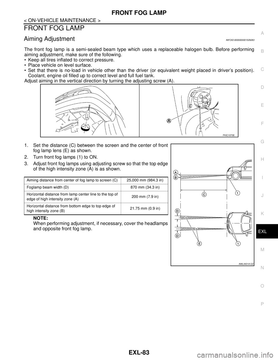
The front fog lamp is a semi-sealed beam type which uses a replaceable halogen bulb. Before performing
aiming adjustment, make sure of the following.
Keep all tires inflated to correct pressure.
Place vehicle on level surface.
Set that there is no-load in vehicle other than the driver (or equivalent weight placed in driver’s position).
Coolant, engine oil filled up to correct level and full fuel tank.
Adjust aiming in the vertical direction by turning the adjusting screw (A).
1. Set the distance (C) between the screen and the center of front
fog lamp lens (E) as shown.
2. Turn front fog lamps (1) to ON.
3. Adjust front fog lamps using adjusting screw so that the top edge
of the high intensity zone (A) is as shown.
NOTE:
When performing adjustment, if necessary, cover the headlamps
and opposite front fog lamp.
PKIC1070E
Aiming distance from center of fog lamp to screen (C) 25,000 mm (984.3 in)
Foglamp beam width (D) 870 mm (34.3 in)
Horizontal distance from lamp center line to the top of
edge of high intensity zone (A)200 mm (7.9 in)
Horizontal distance from bottom edge to top edge of
high intensity zone (B)21.75 mm (0.9 in)
AWLIA0141ZZ
Page 3178 of 5883
FSU-2
< PRECAUTION >
PRECAUTIONS
PRECAUTION
PRECAUTIONS
Precaution for Supplemental Restraint System (SRS) "AIR BAG" and "SEAT BELT
PRE-TENSIONER"
INFOID:0000000001716875
The Supplemental Restraint System such as “AIR BAG” and “SEAT BELT PRE-TENSIONER”, used along
with a front seat belt, helps to reduce the risk or severity of injury to the driver and front passenger for certain
types of collision. This system includes seat belt switch inputs and dual stage front air bag modules. The SRS
system uses the seat belt switches to determine the front air bag deployment, and may only deploy one front
air bag, depending on the severity of a collision and whether the front occupants are belted or unbelted.
Information necessary to service the system safely is included in the SR and SB section of this Service Man-
ual.
WARNING:
• To avoid rendering the SRS inoperative, which could increase the risk of personal injury or death in
the event of a collision which would result in air bag inflation, all maintenance must be performed by
an authorized NISSAN/INFINITI dealer.
Improper maintenance, including incorrect removal and installation of the SRS, can lead to personal
injury caused by unintentional activation of the system. For removal of Spiral Cable and Air Bag
Module, see the SR section.
Do not use electrical test equipment on any circuit related to the SRS unless instructed to in this
Service Manual. SRS wiring harnesses can be identified by yellow and/or orange harnesses or har-
ness connectors.
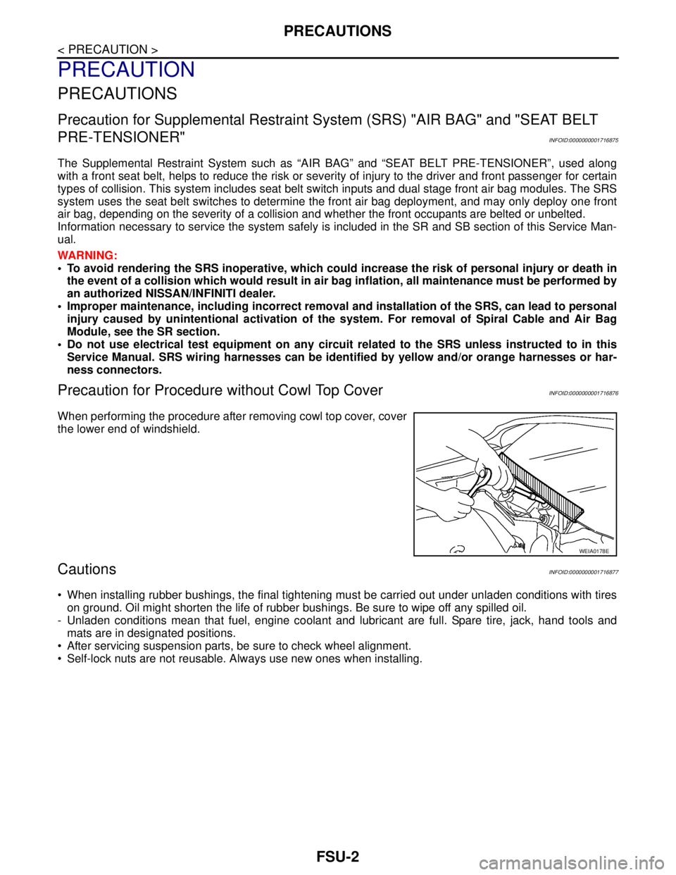
Precaution for Procedure without Cowl Top CoverINFOID:0000000001716876
When performing the procedure after removing cowl top cover, cover
the lower end of windshield.
CautionsINFOID:0000000001716877
When installing rubber bushings, the final tightening must be carried out under unladen conditions with tires
on ground. Oil might shorten the life of rubber bushings. Be sure to wipe off any spilled oil.
- Unladen conditions mean that fuel, engine coolant and lubricant are full. Spare tire, jack, hand tools and
mats are in designated positions.
After servicing suspension parts, be sure to check wheel alignment.
Self-lock nuts are not reusable. Always use new ones when installing.
WEIA0178E
Page 3182 of 5883
FSU-6
< ON-VEHICLE MAINTENANCE >
FRONT SUSPENSION ASSEMBLY
ON-VEHICLE MAINTENANCE
FRONT SUSPENSION ASSEMBLY
On-Vehicle Inspection and ServiceINFOID:0000000001716890
Make sure the mounting conditions (looseness, back lash) of each component and component conditions
(wear, damage) are normal.
INSPECTION OF LOWER BALL JOINT END PLAY
1. Set front wheels in a straight-ahead position. Do not depress brake pedal.
2. Place an iron bar or similar tool between transverse link and steering knuckle.
3. Measure axial end play by prying it up and down.
CAUTION:
Be careful not to damage ball joint boot. Do not damage the installation position by applying
excessive force.
STRUT INSPECTION
Check for oil leakage, damage and replace as necessary.
Wheel Alignment InspectionINFOID:0000000001716891
PRELIMINARY INSPECTION
WARNING:
Always adjust the alignment with the vehicle on a flat surface.
NOTE:
If alignment is out of specification, inspect and replace any damaged or worn rear suspension parts before
making any adjustments.
1. Check and adjust the wheel alignment with the vehicle under unladen conditions. “Unladen conditions”
means that the fuel, coolant, and lubricant are full; and that the spare tire, jack, hand tools and mats are in
their designated positions.
2. Check the tires for incorrect air pressure and excessive wear.
3. Check the wheels for run out and damage. Refer to WT-5, "
Inspection" .
4. Check the wheel bearing axial end play. Refer to FA X - 5 , "
On-Vehicle Inspection and Service" .
5. Check the shock absorbers for leaks or damage.
6. Check each mounting point of the suspension components for any excessive looseness or damage.
7. Check each link, arm, and the suspension member for any damage.
8. Check the vehicle height. Refer to FSU-18, "
Wheelarch Height (Unladen*)" .
GENERAL INFORMATION AND RECOMMENDATIONS
1. A Four-Wheel Thrust Alignment should be performed.
This type of alignment is recommended for any NISSAN vehicle.
The four-wheel “thrust” process helps ensure that the vehicle is properly aligned and the steering wheel
is centered.
The alignment machine itself should be capable of accepting any NISSAN vehicle.
The alignment machine should be checked to ensure that it is level.
2. Make sure the alignment machine is properly calibrated.
Your alignment machine should be regularly calibrated in order to give correct information.
Check with the manufacturer of your specific alignment machine for their recommended Service/Cali-
bration Schedule.
THE ALIGNMENT PROCESS
IMPORTANT: Use only the alignment specifications listed in this Service Manual. Refer to FSU-17, "Wheel
Alignment (Unladen*)" .
1. When displaying the alignment settings, many alignment machines use “indicators”: (Green/red, plus or
minus, Go/No Go). Do NOT use these indicators. Axial end play : 0 mm (0 in)
Page 3233 of 5883
IDENTIFICATION INFORMATION
GI-39
< FEATURES OF NEW MODEL >
C
D
E
F
G
H
I
J
K
L
MB
GI
N
O
P
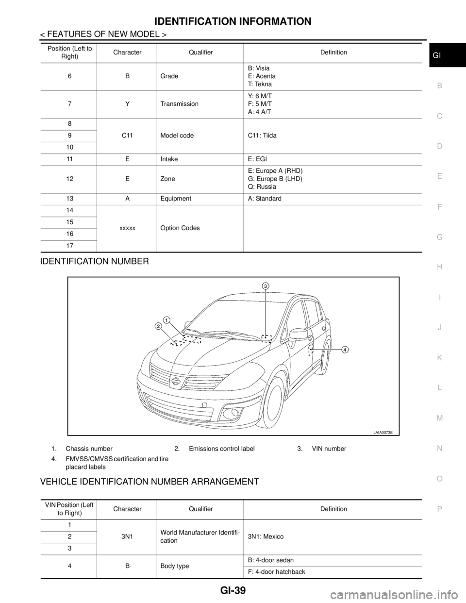
IDENTIFICATION NUMBER
VEHICLE IDENTIFICATION NUMBER ARRANGEMENT
6BGradeB: Visia
E: Acenta
T: Te k n a
7 Y TransmissionY: 6 M/ T
F: 5 M/T
A: 4 A/T
8
C11 Model code C11: Tiida 9
10
11 E Intake E: EGI
12 E ZoneE: Europe A (RHD)
G: Europe B (LHD)
Q: Russia
13 A Equipment A: Standard
14
xxxxx Option Codes 15
16
17 Position (Left to
Right)Character Qualifier Definition
1. Chassis number 2. Emissions control label 3. VIN number
4. FMVSS/CMVSS certification and tire
placard labels
LAIA0073E
VIN Position (Left
to Right)Character Qualifier Definition
1
3N1World Manufacturer Identifi-
cation3N1: Mexico 2
3
4 B Body typeB: 4-door sedan
F: 4-door hatchback
Page 4293 of 5883
CHASSIS AND BODY MAINTENANCE
MA-53
< ON-VEHICLE MAINTENANCE >
C
D
E
F
G
H
I
J
K
L
MB
MAN
OA
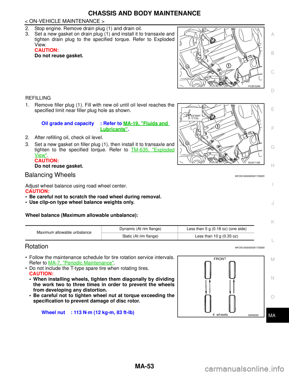
2. Stop engine. Remove drain plug (1) and drain oil.
3. Set a new gasket on drain plug (1) and install it to transaxle and
tighten drain plug to the specified torque. Refer to Exploded
View.
CAUTION:
Do not reuse gasket.
REFILLING
1. Remove filler plug (1). Fill with new oil until oil level reaches the
specified limit near filler plug hole as shown.
2. After refilling oil, check oil level.
3. Set a new gasket on filler plug (1), then install it to transaxle and
tighten to the specified torque. Refer to TM-635, "
Exploded
View".
CAUTION:
Do not reuse gasket.
Balancing WheelsINFOID:0000000001730925
Adjust wheel balance using road wheel center.
CAUTION:
Be careful not to scratch the road wheel during removal.
Use clip-on type wheel balance weights only.
Wheel balance (Maximum allowable unbalance):
RotationINFOID:0000000001730926
Follow the maintenance schedule for tire rotation service intervals.
Refer to MA-7, "
Periodic Maintenance".
Do not include the T-type spare tire when rotating tires.
CAUTION:
When installing wheels, tighten them diagonally by dividing
the work two to three times in order to prevent the wheels
from developing any distortion.
Be careful not to tighten wheel nut at torque exceeding the
specification to prevent damage of disc rotor.
PCIB1504E
Oil grade and capacity : Refer to MA-19, "Fluids and
Lubricants".
SCIA7119E
Maximum allowable unbalanceDynamic (At rim flange) Less than 5 g (0.18 oz) (one side)
Static (At rim flange) Less than 10 g (0.35 oz)
Wheel nut : 113 N·m (12 kg-m, 83 ft-lb)SMA829C