wheel bolts NISSAN TIIDA 2007 Service User Guide
[x] Cancel search | Manufacturer: NISSAN, Model Year: 2007, Model line: TIIDA, Model: NISSAN TIIDA 2007Pages: 5883, PDF Size: 78.95 MB
Page 513 of 5883
CO-32
< PRECAUTION >[MR18DE]
PRECAUTIONS
PRECAUTION
PRECAUTIONS
Precaution for Supplemental Restraint System (SRS) "AIR BAG" and "SEAT BELT
PRE-TENSIONER"
INFOID:0000000001516585
The Supplemental Restraint System such as “AIR BAG” and “SEAT BELT PRE-TENSIONER”, used along
with a front seat belt, helps to reduce the risk or severity of injury to the driver and front passenger for certain
types of collision. Information necessary to service the system safely is included in the SR and SB section of
this Service Manual.
WARNING:
To avoid rendering the SRS inoperative, which could increase the risk of personal injury or death in
the event of a collision which would result in air bag inflation, all maintenance must be performed by
an authorized NISSAN/INFINITI dealer.
Improper maintenance, including incorrect removal and installation of the SRS, can lead to personal
injury caused by unintentional activation of the system. For removal of Spiral Cable and Air Bag
Module, see the SR section.
Do not use electrical test equipment on any circuit related to the SRS unless instructed to in this
Service Manual. SRS wiring harnesses can be identified by yellow and/or orange harnesses or har-
ness connectors.
Precaution Necessary for Steering Wheel Rotation After Battery Disconnect
INFOID:0000000001337832
NOTE:
This Procedure is applied only to models with Intelligent Key system and NATS (NISSAN ANTI-THEFT SYS-
TEM).
Remove and install all control units after disconnecting both battery cables with the ignition knob in the
″LOCK″ position.
Always use CONSULT-II to perform self-diagnosis as a part of each function inspection after finishing work.
If DTC is detected, perform trouble diagnosis according to self-diagnostic results.
For models equipped with the Intelligent Key system and NATS, an electrically controlled steering lock mech-
anism is adopted on the key cylinder.
For this reason, if the battery is disconnected or if the battery is discharged, the steering wheel will lock and
steering wheel rotation will become impossible.
If steering wheel rotation is required when battery power is interrupted, follow the procedure below before
starting the repair operation.
OPERATION PROCEDURE
1. Connect both battery cables.
NOTE:
Supply power using jumper cables if battery is discharged.
2. Use the Intelligent Key or mechanical key to turn the ignition switch to the ″ACC″ position. At this time, the
steering lock will be released.
3. Disconnect both battery cables. The steering lock will remain released and the steering wheel can be
rotated.
4. Perform the necessary repair operation.
5. When the repair work is completed, return the ignition switch to the ″LOCK″ position before connecting
the battery cables. (At this time, the steering lock mechanism will engage.)
6. Perform a self-diagnosis check of all control units using CONSULT-II.
Precaution for Liquid GasketINFOID:0000000001337833
REMOVAL OF LIQUID GASKET SEALING
After removing nuts and bolts, separate the mating surface, using Tool and remove old liquid gasket sealing.
Page 536 of 5883
PRECAUTIONS
CO-55
< PRECAUTION >[K9K]
C
D
E
F
G
H
I
J
K
L
MA
CO
N
P O
PRECAUTION
PRECAUTIONS
Precaution for Supplemental Restraint System (SRS) "AIR BAG" and "SEAT BELT
PRE-TENSIONER"
INFOID:0000000001534592
The Supplemental Restraint System such as “AIR BAG” and “SEAT BELT PRE-TENSIONER”, used along
with a front seat belt, helps to reduce the risk or severity of injury to the driver and front passenger for certain
types of collision. Information necessary to service the system safely is included in the SR and SB section of
this Service Manual.
WARNING:
To avoid rendering the SRS inoperative, which could increase the risk of personal injury or death in
the event of a collision which would result in air bag inflation, all maintenance must be performed by
an authorized NISSAN/INFINITI dealer.
Improper maintenance, including incorrect removal and installation of the SRS, can lead to personal
injury caused by unintentional activation of the system. For removal of Spiral Cable and Air Bag
Module, see the SR section.
Do not use electrical test equipment on any circuit related to the SRS unless instructed to in this
Service Manual. SRS wiring harnesses can be identified by yellow and/or orange harnesses or har-
ness connectors.
Precaution Necessary for Steering Wheel Rotation After Battery Disconnect
INFOID:0000000001534593
NOTE:
This Procedure is applied only to models with Intelligent Key system and NATS (NISSAN ANTI-THEFT SYS-
TEM).
Remove and install all control units after disconnecting both battery cables with the ignition knob in the
″LOCK″ position.
Always use CONSULT-II to perform self-diagnosis as a part of each function inspection after finishing work.
If DTC is detected, perform trouble diagnosis according to self-diagnostic results.
For models equipped with the Intelligent Key system and NATS, an electrically controlled steering lock mech-
anism is adopted on the key cylinder.
For this reason, if the battery is disconnected or if the battery is discharged, the steering wheel will lock and
steering wheel rotation will become impossible.
If steering wheel rotation is required when battery power is interrupted, follow the procedure below before
starting the repair operation.
OPERATION PROCEDURE
1. Connect both battery cables.
NOTE:
Supply power using jumper cables if battery is discharged.
2. Use the Intelligent Key or mechanical key to turn the ignition switch to the ″ACC″ position. At this time, the
steering lock will be released.
3. Disconnect both battery cables. The steering lock will remain released and the steering wheel can be
rotated.
4. Perform the necessary repair operation.
5. When the repair work is completed, return the ignition switch to the ″LOCK″ position before connecting
the battery cables. (At this time, the steering lock mechanism will engage.)
6. Perform a self-diagnosis check of all control units using CONSULT-II.
Precaution for Liquid GasketINFOID:0000000001534594
REMOVAL OF LIQUID GASKET SEALING
After removing nuts and bolts, separate the mating surface, using Tool and remove old liquid gasket sealing.
Page 2655 of 5883
EM-8
< PRECAUTION >[HR16DE]
PRECAUTIONS
3. Disconnect both battery cables. The steering lock will remain released and the steering wheel can be
rotated.
4. Perform the necessary repair operation.
5. When the repair work is completed, return the ignition switch to the ″LOCK″ position before connecting
the battery cables. (At this time, the steering lock mechanism will engage.)
6. Perform a self-diagnosis check of all control units using CONSULT-II.
Precaution for Drain CoolantINFOID:0000000001527635
Drain coolant when engine is cooled.
Precaution for Disconnecting Fuel PipingINFOID:0000000001527636
Before starting work, make sure no fire or spark producing items are in the work area.
Release fuel pressure before disassembly.
After disconnecting pipes, plug openings to stop fuel leakage.
Precaution for Removal and DisassemblyINFOID:0000000001527637
When instructed to use special service tools, use the specified tools. Always be careful to work safely, avoid
forceful or uninstructed operations.
Exercise maximum care to avoid damage to mating or sliding surfaces.
Cover openings of engine system with tape or the equivalent, if necessary, to seal out foreign materials.
Mark and arrange disassembly parts in an organized way for easy troubleshooting and assembly.
When loosening nuts and bolts, as a basic rule, start with the one furthest outside, then the one diagonally
opposite, and so on. If the order of loosening is specified, do exactly as specified. Power tools may be used
where noted in the step.
Precaution for Inspection, Repair and ReplacementINFOID:0000000001527638
Before repairing or replacing, thoroughly inspect parts. Inspect new replacement parts in the same way, and
replace if necessary.
Precaution for Assembly and InstallationINFOID:0000000001527639
Use torque wrench to tighten bolts or nuts to specification.
When tightening nuts and bolts, as a basic rule, equally tighten in several different steps starting with the
ones in center, then ones on inside and outside diagonally in this order. If the order of tightening is specified,
do exactly as specified.
Replace with new gasket, packing, oil seal or O-ring.
Thoroughly wash, clean, and air-blow each part. Carefully check oil or coolant passages for any restriction
and blockage.
Avoid damaging sliding or mating surfaces. Completely remove foreign materials such as cloth lint or dust.
Before assembly, oil sliding surfaces well.
Release air within route after draining coolant.
Before starting engine, apply fuel pressure to fuel lines with turning ignition switch ON (with engine stopped).
Then make sure that there are no leaks at fuel line connections.
After repairing, start engine and increase engine speed to check coolant, fuel, oil, and exhaust systems for
leakage.
Parts Requiring Angular TighteningINFOID:0000000001527640
Use an angle wrench for the final tightening of the following engine parts:
- Cylinder head bolts
- Camshaft sprocket (INT)
- Main bearing cap bolts
- Connecting rod cap nuts
- Crankshaft pulley bolt (No angle wrench is required as the bolt flange is provided with notches for angular
tightening)
Do not use a torque value for final tightening. Tool number : KV10112100 (BT-8653-A)
Page 2736 of 5883
ENGINE ASSEMBLY
EM-89
< REMOVAL AND INSTALLATION >[HR16DE]
C
D
E
F
G
H
I
J
K
L
MA
EM
N
P O
REMOVAL AND INSTALLATION
ENGINE ASSEMBLY
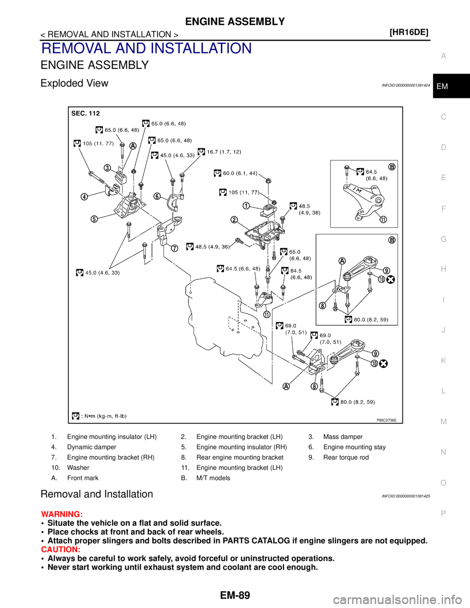
Exploded ViewINFOID:0000000001381424
Removal and InstallationINFOID:0000000001381425
WARNING:
Situate the vehicle on a flat and solid surface.
Place chocks at front and back of rear wheels.
Attach proper slingers and bolts described in PARTS CATALOG if engine slingers are not equipped.
CAUTION:
Always be careful to work safely, avoid forceful or uninstructed operations.
Never start working until exhaust system and coolant are cool enough.
1. Engine mounting insulator (LH) 2. Engine mounting bracket (LH) 3. Mass damper
4. Dynamic damper 5. Engine mounting insulator (RH) 6. Engine mounting stay
7. Engine mounting bracket (RH) 8. Rear engine mounting bracket 9. Rear torque rod
10. Washer 11. Engine mounting bracket (LH)
A. Front mark B. M/T models
PBIC3736E
Page 2738 of 5883
ENGINE ASSEMBLY
EM-91
< REMOVAL AND INSTALLATION >[HR16DE]
C
D
E
F
G
H
I
J
K
L
MA
EM
N
P O Vehicle Underbody
1. Remove front wheel sensor (LH and RH) for ABS from steering knuckle. Refer to BRC-83, "Removal and
Installation".
2. Remove brake caliper assembly with piping connected from steering knuckle. Temporarily secure it on the
vehicle side with a rope to avoid load on it. Refer to BR-24, "
Component".
3. Remove drive shafts (LH and RH) from steering knuckle. Refer to FAX-7, "
Removal and Installation".
4. Remove exhaust front tube. Refer to EX-5, "
Component".
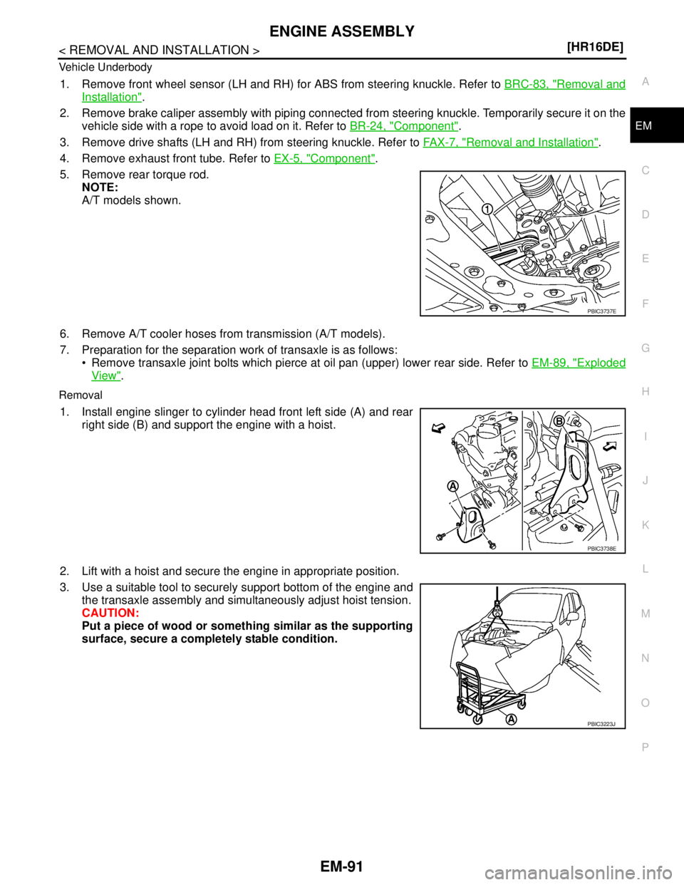
5. Remove rear torque rod.
NOTE:
A/T models shown.
6. Remove A/T cooler hoses from transmission (A/T models).
7. Preparation for the separation work of transaxle is as follows:
Remove transaxle joint bolts which pierce at oil pan (upper) lower rear side. Refer to EM-89, "
Exploded
View".
Removal
1. Install engine slinger to cylinder head front left side (A) and rear
right side (B) and support the engine with a hoist.
2. Lift with a hoist and secure the engine in appropriate position.
3. Use a suitable tool to securely support bottom of the engine and
the transaxle assembly and simultaneously adjust hoist tension.
CAUTION:
Put a piece of wood or something similar as the supporting
surface, secure a completely stable condition.
PBIC3737E
PBIC3738E
PBIC3223J
Page 2741 of 5883
EM-94
< DISASSEMBLY AND ASSEMBLY >[HR16DE]
ENGINE STAND SETTING
DISASSEMBLY AND ASSEMBLY
ENGINE STAND SETTING
SettingINFOID:0000000001381427
NOTE:
Explained here is how to disassemble with engine stand supporting transmission surface. When using differ-
ent type of engine stand, note with difference in steps and etc.
1. Remove the engine and the transaxle assembly from the vehicle, and separate the transaxle from the
engine. Refer to EM-89, "
Exploded View".
2. Remove clutch cover and clutch disc. Refer to CL-13, "
Removal and Installation".
3. Remove flywheel.
Secure flywheel with a stopper plate [SST: KV11105210], and remove mounting bolts.
CAUTION:
Never disassemble flywheel.
Never place flywheel with signal plate facing down.
When handling signal plate, take care not to damage or scratch it.
Handle signal plate in a manner that prevents it from becoming magnetized.
4. Lift the engine with a hoist to install it onto widely use engine stand.
CAUTION:
Use the engine stand that has a load capacity [approximately 135 kg (298 lb) or more] large
enough for supporting the engine weight.
If the load capacity of stand is not adequate, remove the following parts beforehand to reduce the poten-
tial risk of overturning stand.
- Intake manifold: Refer to EM-29, "
Exploded View".
- Exhaust manifold: Refer to EM-32, "
Exploded View".
- Rocker cover: Refer to EM-47, "
Exploded View".
NOTE:
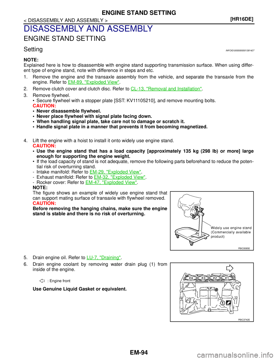
The figure shows an example of widely use engine stand that
can support mating surface of transaxle with flywheel removed.
CAUTION:
Before removing the hanging chains, make sure the engine
stand is stable and there is no risk of overturning.
5. Drain engine oil. Refer to LU-7, "
Draining".
6. Drain engine coolant by removing water drain plug (1) from
inside of the engine.
Use Genuine Liquid Gasket or equivalent.
PBIC0085E
: Engine front
PBIC3742E
Page 2754 of 5883
CYLINDER BLOCK
EM-107
< DISASSEMBLY AND ASSEMBLY >[HR16DE]
C
D
E
F
G
H
I
J
K
L
MA
EM
N
P O
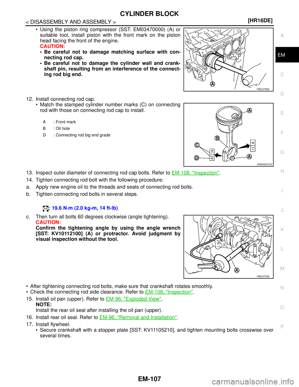
Using the piston ring compressor (SST: EM03470000) (A) or
suitable tool, install piston with the front mark on the piston
head facing the front of the engine.
CAUTION:
Be careful not to damage matching surface with con-
necting rod cap.
Be careful not to damage the cylinder wall and crank-
shaft pin, resulting from an interference of the connect-
ing rod big end.
12. Install connecting rod cap.
Match the stamped cylinder number marks (C) on connecting
rod with those on connecting rod cap to install.
13. Inspect outer diameter of connecting rod cap bolts. Refer to EM-108, "
Inspection".
14. Tighten connecting rod bolt with the following procedure:
a. Apply new engine oil to the threads and seats of connecting rod bolts.
b. Tighten connecting rod bolts in several steps.
c. Then turn all bolts 60 degrees clockwise (angle tightening).
CAUTION:
Confirm the tightening angle by using the angle wrench
[SST: KV10112100] (A) or protractor. Avoid judgment by
visual inspection without the tool.
After tightening connecting rod bolts, make sure that crankshaft rotates smoothly.
Check the connecting rod side clearance. Refer to EM-108, "
Inspection".
15. Install oil pan (upper). Refer to EM-96, "
Exploded View".
NOTE:
Install the rear oil seal after installing the oil pan (upper).
16. Install rear oil seal. Refer to EM-96, "
Removal and Installation".
17. Install flywheel.
Secure crankshaft with a stopper plate [SST: KV11105210], and tighten mounting bolts crosswise over
several times.
PBIC3765E
A: Front mark
B: Oil hole
D : Connecting rod big end grade
JPBIA0537ZZ
: 19.6 N·m (2.0 kg-m, 14 ft-lb)
PBIC3753E
Page 2782 of 5883
PRECAUTIONS
EM-135
< PRECAUTION >[MR18DE]
C
D
E
F
G
H
I
J
K
L
MA
EM
N
P O
3. Disconnect both battery cables. The steering lock will remain released and the steering wheel can be
rotated.
4. Perform the necessary repair operation.
5. When the repair work is completed, return the ignition switch to the ″LOCK″ position before connecting
the battery cables. (At this time, the steering lock mechanism will engage.)
6. Perform a self-diagnosis check of all control units using CONSULT-II.
Precaution for Drain CoolantINFOID:0000000001337765
Drain coolant when engine is cooled.
Precaution for Disconnecting Fuel PipingINFOID:0000000001337766
Before starting work, make sure no fire or spark producing items are in the work area.
Release fuel pressure before disassembly.
After disconnecting pipes, plug openings to stop fuel leakage.
Precaution for Removal and DisassemblyINFOID:0000000001337767
When instructed to use special service tools, use the specified tools. Always be careful to work safely, avoid
forceful or uninstructed operations.
Exercise maximum care to avoid damage to mating or sliding surfaces.
Cover openings of engine system with tape or the equivalent, if necessary, to seal out foreign materials.
Mark and arrange disassembly parts in an organized way for easy troubleshooting and assembly.
When loosening nuts and bolts, as a basic rule, start with the one furthest outside, then the one diagonally
opposite, and so on. If the order of loosening is specified, do exactly as specified. Power tools may be used
where noted in the step.
Precaution for Inspection, Repair and ReplacementINFOID:0000000001337768
Before repairing or replacing, thoroughly inspect parts. Inspect new replacement parts in the same way, and
replace if necessary.
Precaution for Assembly and InstallationINFOID:0000000001337769
Use torque wrench to tighten bolts or nuts to specification.
When tightening nuts and bolts, as a basic rule, equally tighten in several different steps starting with the
ones in center, then ones on inside and outside diagonally in this order. If the order of tightening is specified,
do exactly as specified.
Replace with new gasket, packing, oil seal or O-ring.
Thoroughly wash, clean, and air-blow each part. Carefully check oil or coolant passages for any restriction
and blockage.
Avoid damaging sliding or mating surfaces. Completely remove foreign materials such as cloth lint or dust.
Before assembly, oil sliding surfaces well.
Release air within route after draining coolant.
Before starting engine, apply fuel pressure to fuel lines with turning ignition switch ON (with engine stopped).
Then make sure that there are no leaks at fuel line connections.
After repairing, start engine and increase engine speed to check coolant, fuel, oil, and exhaust systems for
leakage.
Parts Requiring Angular TighteningINFOID:0000000001337770
Use an angle wrench for the final tightening of the following engine parts:
- Cylinder head bolts
- Camshaft sprocket (INT)
- Main bearing cap bolts
- Connecting rod cap nuts
- Crankshaft pulley bolt (No angle wrench is required as the bolt flange is provided with notches for angular
tightening)
Do not use a torque value for final tightening. Tool number : KV10112100 (BT-8653-A)
Page 2788 of 5883
PREPARATION
EM-141
< PREPARATION >[MR18DE]
C
D
E
F
G
H
I
J
K
L
MA
EM
N
P O
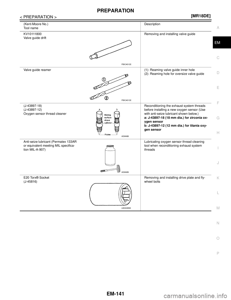
KV10111800
Valve guide driftRemoving and installing valve guide
Valve guide reamer (1): Reaming valve guide inner hole
(2): Reaming hole for oversize valve guide
(J-43897-18)
(J-43897-12)
Oxygen sensor thread cleanerReconditioning the exhaust system threads
before installing a new oxygen sensor (Use
with anti-seize lubricant shown below.)
a: J-43897-18 (18 mm dia.) for zirconia ox-
ygen sensor
b: J-43897-12 (12 mm dia.) for titania oxy-
gen sensor
Anti-seize lubricant (Permatex 133AR
or equivalent meeting MIL specifica-
tion MIL-A-907)Lubricating oxygen sensor thread cleaning
tool when reconditioning exhaust system
threads
E20 Torx® Socket
(J-45816)Removing and installing drive plate and fly-
wheel bolts (Kent-Moore No.)
Tool nameDescription
PBIC4012E
PBIC4013E
AEM488
AEM489
LBIA0285E
Page 2814 of 5883
OIL PAN
EM-167
< ON-VEHICLE REPAIR >[MR18DE]
C
D
E
F
G
H
I
J
K
L
MA
EM
N
P O
2. Remove engine and transaxle assembly. Refer to EM-207.
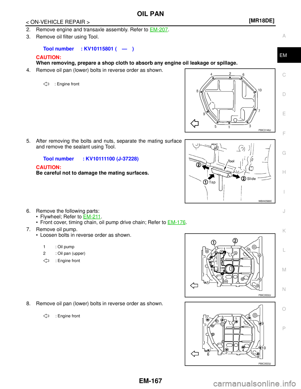
3. Remove oil filter using Tool.
CAUTION:
When removing, prepare a shop cloth to absorb any engine oil leakage or spillage.
4. Remove oil pan (lower) bolts in reverse order as shown.
5. After removing the bolts and nuts, separate the mating surface
and remove the sealant using Tool.
CAUTION:
Be careful not to damage the mating surfaces.
6. Remove the following parts:
Flywheel; Refer to EM-211
.
Front cover, timing chain, oil pump drive chain; Refer to EM-176
.
7. Remove oil pump.
Loosen bolts in reverse order as shown.
8. Remove oil pan (lower) bolts in reverse order as shown.Tool number : KV10115801 ( — )
: Engine front
PBIC3146J
Tool number : KV10111100 (J-37228)
WBIA0566E
1: Oil pump
2 : Oil pan (upper)
: Engine front
PBIC3532J
: Engine front
PBIC3533J