mirror NISSAN TIIDA 2007 Service Owner's Manual
[x] Cancel search | Manufacturer: NISSAN, Model Year: 2007, Model line: TIIDA, Model: NISSAN TIIDA 2007Pages: 5883, PDF Size: 78.95 MB
Page 3306 of 5883

HA-24
< ON-VEHICLE MAINTENANCE >
FLUORESCENT LEAK DETECTOR
FLUORESCENT LEAK DETECTOR
Checking System for Leaks Using the Fluorescent Leak DetectorINFOID:0000000001396445
1. Check A/C system for leaks using the UV lamp and safety goggles J-42220 in a low sunlight area (area
without windows preferable). Illuminate all components, fittings and lines. The dye will appear as a bright
green/yellow area at the point of leakage. Fluorescent dye observed at the evaporator drain opening indi-
cates an evaporator core assembly (tubes, core or expansion valve) leak.
2. If the suspected area is difficult to see, use an adjustable mirror or wipe the area with a clean shop rag or
cloth, with the UV lamp for dye residue.
3. After the leak is repaired, remove any residual dye using dye cleaner J-43872 to prevent future misdiag-
nosis.
4. Perform a system performance check and verify the leak repair with an approved electronic refrigerant
leak detector.
NOTE:
Other gases in the work area or substances on the A/C components, for example, anti-freeze, windshield
washer fluid, solvents and oils, may falsely trigger the leak detector. Make sure the surfaces to be checked are
clean.
Clean with a dry cloth or blow off with shop air.
Do not allow the sensor tip of the detector to contact with any substance. This can also cause false readings
and may damage the detector.
Dye InjectionINFOID:0000000001396446
(This procedure is only necessary when recharging the system or when the compressor has seized and was
replaced.)
1. Check A/C system static (at rest) pressure. Pressure must be at least 345 kPa (3.45 bar, 3.52 kg/cm
2, 50
psi).
2. Pour one bottle (1/4 ounce / 7.4 cc) of the A/C refrigerant dye into the injector tool J-41459.
3. Connect the injector tool to the A/C low-pressure side service fitting.
4. Start engine and switch A/C ON.
5. When the A/C operating (compressor running), inject one bottle (1/4 ounce / 7.4 cc) of fluorescent dye
through the low-pressure service valve using dye injector tool J-41459 (refer to the manufacture’s operat-
ing instructions).
6. With the engine still running, disconnect the injector tool from the service fitting.
CAUTION:
Be careful the A/C system or replacing a component, pour the dye directly into the open system
connection and proceed with the service procedures.
7. Operate the A/C system for a minimum of 20 minutes to mix the dye with the system oil. Depending on the
leak size, operating conditions and location of the leak, it may take from minutes to days for the dye to
penetrate a leak and become visible.
Page 3666 of 5883
INTERIOR ROOM LAMP POWER SUPPLY CIRCUIT
INL-15
< COMPONENT DIAGNOSIS >
C
D
E
F
G
H
I
J
K
MA
B
INL
N
O
P
INTERIOR ROOM LAMP POWER SUPPLY CIRCUIT
DescriptionINFOID:0000000001728870
Provides the interior room lamp power supply. Also cuts the power supply when the interior room lamp battery
saver activating.
Component Function CheckINFOID:0000000001728871
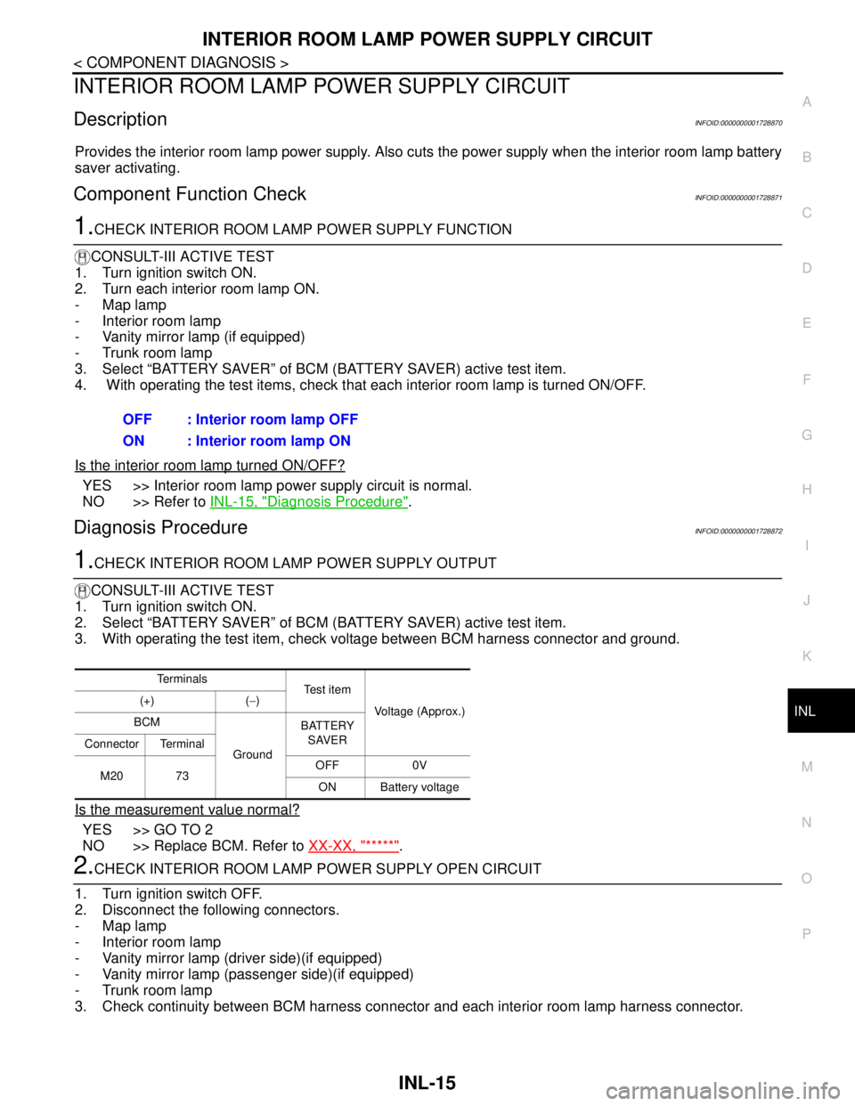
1.CHECK INTERIOR ROOM LAMP POWER SUPPLY FUNCTION
CONSULT-III ACTIVE TEST
1. Turn ignition switch ON.
2. Turn each interior room lamp ON.
- Map lamp
- Interior room lamp
- Vanity mirror lamp (if equipped)
- Trunk room lamp
3. Select “BATTERY SAVER” of BCM (BATTERY SAVER) active test item.
4. With operating the test items, check that each interior room lamp is turned ON/OFF.
Is the interior room lamp turned ON/OFF?
YES >> Interior room lamp power supply circuit is normal.
NO >> Refer to INL-15, "
Diagnosis Procedure".
Diagnosis ProcedureINFOID:0000000001728872
1.CHECK INTERIOR ROOM LAMP POWER SUPPLY OUTPUT
CONSULT-III ACTIVE TEST
1. Turn ignition switch ON.
2. Select “BATTERY SAVER” of BCM (BATTERY SAVER) active test item.
3. With operating the test item, check voltage between BCM harness connector and ground.
Is the measurement value normal?
YES >> GO TO 2
NO >> Replace BCM. Refer to XX-XX, "*****"
.
2.CHECK INTERIOR ROOM LAMP POWER SUPPLY OPEN CIRCUIT
1. Turn ignition switch OFF.
2. Disconnect the following connectors.
- Map lamp
- Interior room lamp
- Vanity mirror lamp (driver side)(if equipped)
- Vanity mirror lamp (passenger side)(if equipped)
- Trunk room lamp
3. Check continuity between BCM harness connector and each interior room lamp harness connector.OFF : Interior room lamp OFF
ON : Interior room lamp ON
Te r m i n a l s
Te s t i t e m
Voltage (Approx.) (+) (−)
BCM
GroundBATTERY
SAVER
Connector Terminal
M20 73OFF 0V
ON Battery voltage
Page 3667 of 5883

INL-16
< COMPONENT DIAGNOSIS >
INTERIOR ROOM LAMP POWER SUPPLY CIRCUIT
Does continuity exist?
YES >> GO TO 3
NO >> Repair the harnesses or connectors.
3.CHECK INTERIOR ROOM LAMP POWER SUPPLY SHORT CIRCUIT
Check continuity between BCM harness connector and ground.
Does continuity exist?
YES >> Repair the harnesses or connectors.
NO >> Check that each interior room lamp has no internal short circuit.
BCM Each interior room lamp
Continu-
ity Connec-
torTerminal Connector Terminal
M20 73Map lamp R2 4
Existed Interior room lamp R7 3
Vanity mirror lamp
RHR10 1
Vanity mirror lamp
LHR9 1
Trunk room lamp B36 1
BCM
GroundContinuity
Connector Terminal
M20 73 Not existed
Page 3674 of 5883
INTERIOR LIGHTING SYSTEM SYMPTOMS
INL-23
< SYMPTOM DIAGNOSIS >
C
D
E
F
G
H
I
J
K
MA
B
INL
N
O
P
SYMPTOM DIAGNOSIS
INTERIOR LIGHTING SYSTEM SYMPTOMS
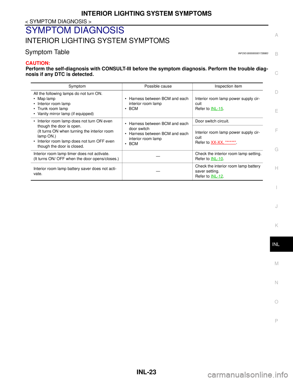
Symptom TableINFOID:0000000001728883
CAUTION:
Perform the self-diagnosis with CONSULT-III before the symptom diagnosis. Perform the trouble diag-
nosis if any DTC is detected.
Symptom Possible cause Inspection item
All the following lamps do not turn ON.
Map lamp
Interior room lamp
Trunk room lamp
Vanity mirror lamp (if equipped) Harness between BCM and each
interior room lamp
BCMInterior room lamp power supply cir-
cuit
Refer to INL-15
.
Interior room lamp does not turn ON even
though the door is open.
(It turns ON when turning the interior room
lamp ON.)
Interior room lamp does not turn OFF even
though the door is closed. Harness between BCM and each
door switch
Harness between BCM and each
interior room lamp
BCMDoor switch circuit.
Interior room lamp power supply cir-
cuit
Refer to XX-XX, "*****"
.
Interior room lamp timer does not activate.
(It turns ON/ OFF when the door opens/closes.)—Check the interior room lamp setting.
Refer to INL-10
.
Interior room lamp battery saver does not acti-
vate.—Check the interior room lamp battery
saver setting.
Refer to INL-12
.
Page 3676 of 5883
INTERIOR ROOM LAMP
INL-25
< ON-VEHICLE REPAIR >
C
D
E
F
G
H
I
J
K
MA
B
INL
N
O
P
ON-VEHICLE REPAIR
INTERIOR ROOM LAMP
Removal and InstallationINFOID:0000000001726698
MAP LAMP
Removal
1. Disconnect the negative battery cable.
2. Insert a suitable tool and release the pawl, then remove map lamp from overhead console assembly.
3. Disconnect the connectors, then remove map lamp.
Installation
Installation is in the reverse order of removal.
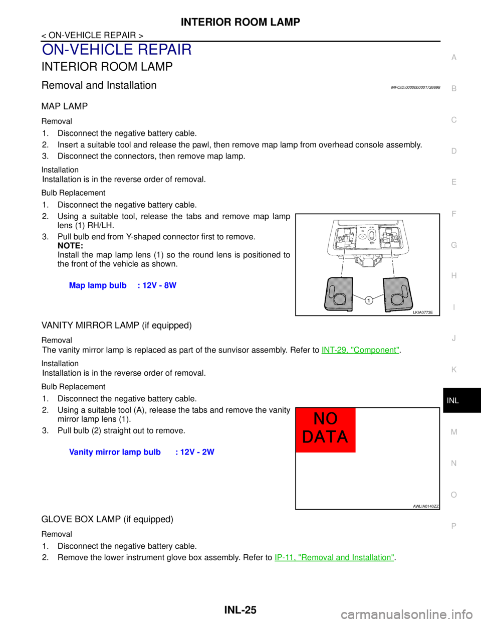
Bulb Replacement
1. Disconnect the negative battery cable.
2. Using a suitable tool, release the tabs and remove map lamp
lens (1) RH/LH.
3. Pull bulb end from Y-shaped connector first to remove.
NOTE:
Install the map lamp lens (1) so the round lens is positioned to
the front of the vehicle as shown.
VANITY MIRROR LAMP (if equipped)
Removal
The vanity mirror lamp is replaced as part of the sunvisor assembly. Refer to INT-29, "Component".
Installation
Installation is in the reverse order of removal.
Bulb Replacement
1. Disconnect the negative battery cable.
2. Using a suitable tool (A), release the tabs and remove the vanity
mirror lamp lens (1).
3. Pull bulb (2) straight out to remove.
GLOVE BOX LAMP (if equipped)
Removal
1. Disconnect the negative battery cable.
2. Remove the lower instrument glove box assembly. Refer to IP-11, "
Removal and Installation". Map lamp bulb : 12V - 8W
LKIA0773E
Vanity mirror lamp bulb : 12V - 2W
AWLIA0140ZZ
Page 3679 of 5883

INL-28
< SERVICE DATA AND SPECIFICATIONS (SDS)
SERVICE DATA AND SPECIFICATIONS (SDS)
SERVICE DATA AND SPECIFICATIONS (SDS)
SERVICE DATA AND SPECIFICATIONS (SDS)
Bulb SpecificationsINFOID:0000000001726700
* Always check with the Parts Department for the latest parts information.Item Type Wattage (W) Bulb No.*
Map lamp Cylinder 8 AL54
Vanity mirror lamp (if equipped) Cylinder 2 -
Glove box lamp (if equipped) Wedge 1.4 -
Room lamp Cylinder 8 -
Luggage compartment lamp (Hatchback) Cylinder 5 B5Y
Trunk room lamp (Sedan) Wedge 5 158
Page 4299 of 5883

MIR-1
DRIVER CONTROLS
C
D
E
F
G
H
I
J
K
M
SECTION MIR
A
B
MIR
N
O
P
CONTENTS
MIRRORS
PRECAUTION ...............................................2
PRECAUTIONS ...................................................2
Precaution for Supplemental Restraint System
(SRS) "AIR BAG" and "SEAT BELT PRE-TEN-
SIONER" ...................................................................
2
COMPONENT DIAGNOSIS ..........................3
DOOR MIRROR ...................................................3
Wiring Diagram — Position Adjustment (LHD) — ......3
Wiring Diagram — Position Adjustment (RHD) — ......4
Wiring Diagram — Power Fold System (LHD) — .....5
Wiring Diagram — Power Fold System (RHD) — .....6
REMOVAL AND INSTALLATION ................7
DOOR MIRROR .................................................7
Removal and Installation ..........................................7
Disassembly and Assembly ......................................8
INSIDE MIRROR ................................................9
Removal and Installation ..........................................9
Page 4301 of 5883
DOOR MIRROR
MIR-3
< COMPONENT DIAGNOSIS >
C
D
E
F
G
H
I
J
K
MA
B
MIR
N
O
P
COMPONENT DIAGNOSIS
DOOR MIRROR
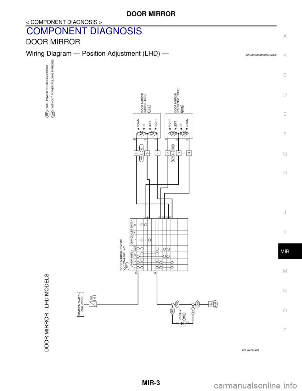
Wiring Diagram — Position Adjustment (LHD) —INFOID:0000000001702329
AWLWA0014GB
Page 4302 of 5883
MIR-4
< COMPONENT DIAGNOSIS >
DOOR MIRROR
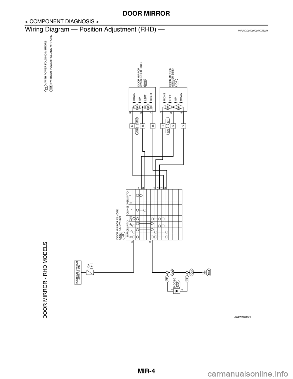
Wiring Diagram — Position Adjustment (RHD) —
INFOID:0000000001728321
AWLWA0015GB
Page 4303 of 5883
DOOR MIRROR
MIR-5
< COMPONENT DIAGNOSIS >
C
D
E
F
G
H
I
J
K
MA
B
MIR
N
O
P
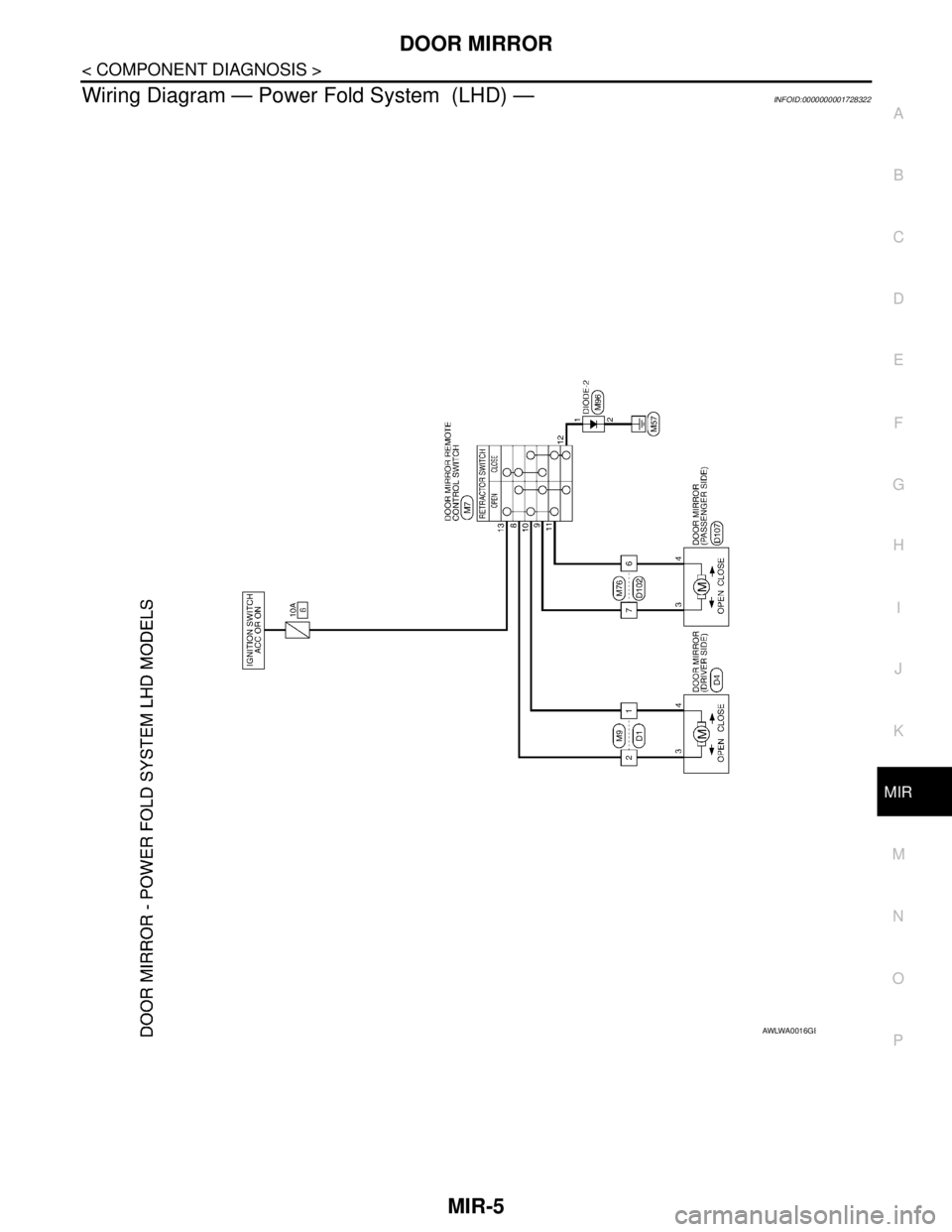
Wiring Diagram — Power Fold System (LHD) —INFOID:0000000001728322
AWLWA0016GB