mirror NISSAN TIIDA 2007 Service User Guide
[x] Cancel search | Manufacturer: NISSAN, Model Year: 2007, Model line: TIIDA, Model: NISSAN TIIDA 2007Pages: 5883, PDF Size: 78.95 MB
Page 580 of 5883
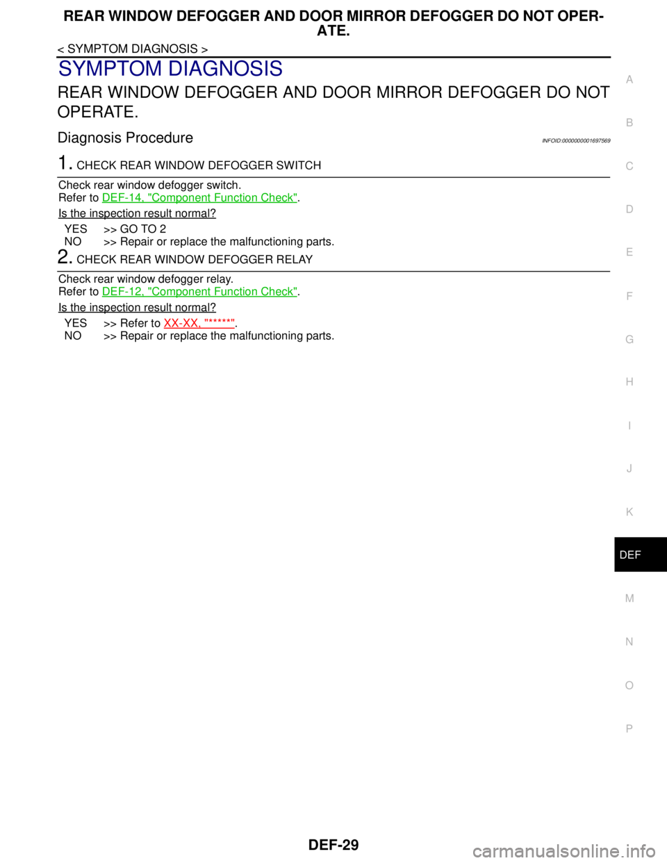
REAR WINDOW DEFOGGER AND DOOR MIRROR DEFOGGER DO NOT OPER-
ATE.
DEF-29
< SYMPTOM DIAGNOSIS >
C
D
E
F
G
H
I
J
K
MA
B
DEF
N
O
P
SYMPTOM DIAGNOSIS
REAR WINDOW DEFOGGER AND DOOR MIRROR DEFOGGER DO NOT
OPERATE.
Diagnosis ProcedureINFOID:0000000001697569
1. CHECK REAR WINDOW DEFOGGER SWITCH
Check rear window defogger switch.
Refer to DEF-14, "
Component Function Check".
Is the inspection result normal?
YES >> GO TO 2
NO >> Repair or replace the malfunctioning parts.
2. CHECK REAR WINDOW DEFOGGER RELAY
Check rear window defogger relay.
Refer to DEF-12, "
Component Function Check".
Is the inspection result normal?
YES >> Refer to XX-XX, "*****".
NO >> Repair or replace the malfunctioning parts.
Page 581 of 5883
DEF-30
< SYMPTOM DIAGNOSIS >
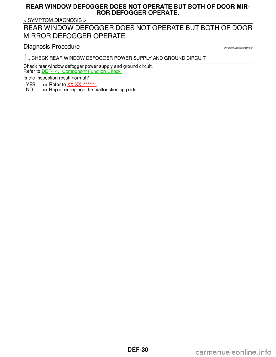
REAR WINDOW DEFOGGER DOES NOT OPERATE BUT BOTH OF DOOR MIR-
ROR DEFOGGER OPERATE.
REAR WINDOW DEFOGGER DOES NOT OPERATE BUT BOTH OF DOOR
MIRROR DEFOGGER OPERATE.
Diagnosis ProcedureINFOID:0000000001697570
1. CHECK REAR WINDOW DEFOGGER POWER SUPPLY AND GROUND CIRCUIT
Check rear window defogger power supply and ground circuit.
Refer to DEF-14, "
Component Function Check".
Is the inspection result normal?
YES >> Refer to XX-XX, "*****".
NO >> Repair or replace the malfunctioning parts.
Page 582 of 5883
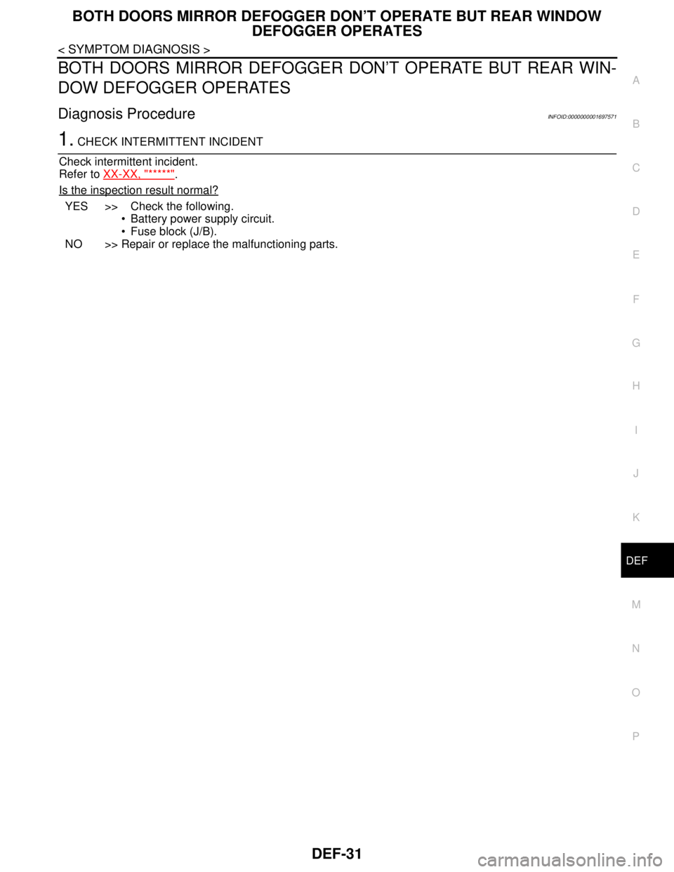
BOTH DOORS MIRROR DEFOGGER DON’T OPERATE BUT REAR WINDOW
DEFOGGER OPERATES
DEF-31
< SYMPTOM DIAGNOSIS >
C
D
E
F
G
H
I
J
K
MA
B
DEF
N
O
P
BOTH DOORS MIRROR DEFOGGER DON’T OPERATE BUT REAR WIN-
DOW DEFOGGER OPERATES
Diagnosis ProcedureINFOID:0000000001697571
1. CHECK INTERMITTENT INCIDENT
Check intermittent incident.
Refer to XX-XX, "*****"
.
Is the inspection result normal?
YES >> Check the following.
Battery power supply circuit.
Fuse block (J/B).
NO >> Repair or replace the malfunctioning parts.
Page 583 of 5883
DEF-32
< SYMPTOM DIAGNOSIS >
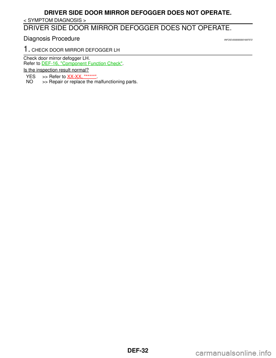
DRIVER SIDE DOOR MIRROR DEFOGGER DOES NOT OPERATE.
DRIVER SIDE DOOR MIRROR DEFOGGER DOES NOT OPERATE.
Diagnosis ProcedureINFOID:0000000001697572
1. CHECK DOOR MIRROR DEFOGGER LH
Check door mirror defogger LH.
Refer to DEF-16, "
Component Function Check".
Is the inspection result normal?
YES >> Refer to XX-XX, "*****".
NO >> Repair or replace the malfunctioning parts.
Page 584 of 5883
PASSENGER SIDE DOOR MIRROR DEFOGGER DOES NOT OPERATE.
DEF-33
< SYMPTOM DIAGNOSIS >
C
D
E
F
G
H
I
J
K
MA
B
DEF
N
O
P
PASSENGER SIDE DOOR MIRROR DEFOGGER DOES NOT OPERATE.
Diagnosis ProcedureINFOID:0000000001697573
1. CHECK DOOR MIRROR DEFOGGER RH
Check door mirror defogger RH.
Refer to DEF-18, "
Component Function Check".
Is the inspection result normal?
YES >> Refer to XX-XX, "*****".
NO >> Repair or replace the malfunctioning parts.
Page 2686 of 5883
![NISSAN TIIDA 2007 Service User Guide FUEL INJECTOR AND FUEL TUBE
EM-39
< ON-VEHICLE REPAIR >[HR16DE]
C
D
E
F
G
H
I
J
K
L
MA
EM
N
P O
c. Align center to insert quick connector straightly into fuel tube.
Insert quick connector to fuel tu NISSAN TIIDA 2007 Service User Guide FUEL INJECTOR AND FUEL TUBE
EM-39
< ON-VEHICLE REPAIR >[HR16DE]
C
D
E
F
G
H
I
J
K
L
MA
EM
N
P O
c. Align center to insert quick connector straightly into fuel tube.
Insert quick connector to fuel tu](/img/5/57395/w960_57395-2685.png)
FUEL INJECTOR AND FUEL TUBE
EM-39
< ON-VEHICLE REPAIR >[HR16DE]
C
D
E
F
G
H
I
J
K
L
MA
EM
N
P O
c. Align center to insert quick connector straightly into fuel tube.
Insert quick connector to fuel tube until the top spool on fuel
tube is inserted completely and the 2nd level spool is posi-
tioned slightly below quick connector bottom end.
CAUTION:
Hold “A” position shown when inserting fuel tube into
quick connector.
Carefully align center to avoid inclined insertion to pre-
vent damage to O-ring inside quick connector.
Insert until you hear a “click” sound and actually feel
the engagement.
To avoid misidentification of engagement with a similar
sound, be sure to perform the next step.
d. Before clamping fuel feed hose with hose clamp, pull quick connector hard by hand holding “A” position.
Make sure it is completely engaged (connected) so that it does not come out from fuel tube.
e. Install quick connector cap (1) to quick connector connection.
Install quick connector cap with the side arrow facing quick
connector side (fuel feed hose side).
CAUTION:
Make sure that the quick connector and fuel tube are
securely engaged with the quick connector cap mount-
ing groove.
Quick connector may not be connected correctly if
quick connector cap cannot be installed easily. Remove
the quick connector cap, and then check the connection
of quick connector again.
f. Install fuel feed hose to hose clamp.
7. Installation is in the reverse order of removal, for the remaining parts.
InspectionINFOID:0000000001381405
INSPECTION AFTER INSTALLATION
Check on Fuel Leakage
1. Turn ignition switch “ON” (with the engine stopped). With fuel pressure applied to fuel piping, make sure
there are no fuel leaks at connection points.
NOTE:
Use mirrors for checking at points out of clear sight.
2. Start the engine. With engine speed increased, make sure again that there are no fuel leaks at connection
points.
CAUTION:
Never touch the engine immediately after stopped, as the engine becomes extremely hot.
KBIA0272E
PBIC3664E
Page 3075 of 5883
EXL-74
< SYMPTOM DIAGNOSIS >
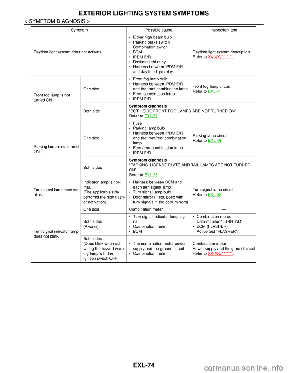
EXTERIOR LIGHTING SYSTEM SYMPTOMS
Daytime light system does not activate. Either high beam bulb
Parking brake switch
Combination switch
BCM
IPDM E/R
Daytime light relay
Harness between IPDM E/R
and daytime light relay.Daytime light system description.
Refer to XX-XX, "*****"
.
Front fog lamp is not
turned ON.One side Front fog lamp bulb
Harness between IPDM E/R
and the front combination lamp
Front combination lamp
IPDM E/RFront fog lamp circuit
Refer to EXL-41
.
Both sideSymptom diagnosis
"BOTH SIDE FRONT FOG LAMPS ARE NOT TURNED ON"
Refer to EXL-79
.
Parking lamp is not turned
ON.One sideFuse
Parking lamp bulb
Harness between IPDM E/R
and the front/rear combination
lamp
Front/rear combination lamp
IPDM E/RParking lamp circuit
Refer to EXL-46
.
Both sidesSymptom diagnosis
"PARKING, LICENSE PLATE AND TAIL LAMPS ARE NOT TURNED
ON"
Refer to EXL-78
.
Turn signal lamp does not
blink.Indicator lamp is nor-
mal.
(The applicable side
performs the high flash-
er activation). Harness between BCM and
each turn signal lamp
Turn signal lamp bulb
Door mirror (if equipped with
turn signals in the door mirrors)Turn signal lamp circuit
Refer to EXL-52
.
Turn signal indicator lamp
does not blink.One side Combination meter —
Both sides
(Always) Turn signal indicator lamp sig-
nal
Combination meter
BCM Combination meter.
Data monitor "TURN IND"
BCM (FLASHER)
Active test "FLASHER"
Both sides
(Does blink when acti-
vating the hazard warn-
ing lamp with the
ignition switch OFF) The combination meter power
supply and the ground circuit
Combination meterCombination meter
Power supply and the ground circuit
Refer to XX-XX, "*****"
. Symptom Possible cause Inspection item
Page 3092 of 5883
AUTO LIGHT SYSTEM
EXL-91
< ON-VEHICLE REPAIR >
C
D
E
F
G
H
I
J
K
MA
B
EXL
N
O
P
AUTO LIGHT SYSTEM
Removal and Installation of Light and Rain SensorINFOID:0000000001530408
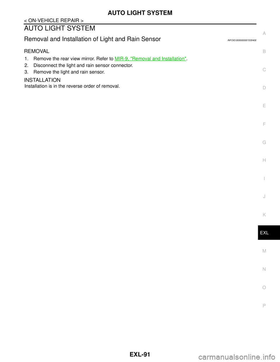
REMOVAL
1. Remove the rear view mirror. Refer to MIR-9, "Removal and Installation".
2. Disconnect the light and rain sensor connector.
3. Remove the light and rain sensor.
INSTALLATION
Installation is in the reverse order of removal.
Page 3221 of 5883
RECOMMENDED CHEMICAL PRODUCTS AND SEALANTS
GI-27
< HOW TO USE THIS MANUAL >
C
D
E
F
G
H
I
J
K
L
MB
GI
N
O
PRECOMMENDED CHEMICAL PRODUCTS AND SEALANTS
Recommended Chemical Products and SealantsINFOID:0000000001691465
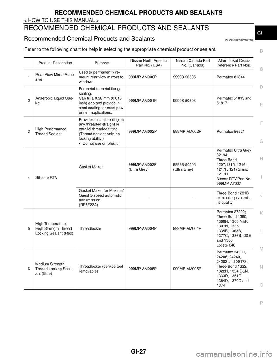
Refer to the following chart for help in selecting the appropriate chemical product or sealant.
Product Description PurposeNissan North America
Part No. (USA)Nissan Canada Part
No. (Canada)Aftermarket Cross-
reference Part Nos.
1Rear View Mirror Adhe-
siveUsed to permanently re-
mount rear view mirrors to
windows.999MP-AM000P 99998-50505 Permatex 81844
2Anaerobic Liquid Gas-
ketFor metal-to-metal flange
sealing.
Can fill a 0.38 mm (0.015
inch) gap and provide in-
stant sealing for most pow-
ertrain applications.999MP-AM001P 99998-50503Permatex 51813 and
51817
3High Performance
Thread SealantProvides instant sealing on
any threaded straight or
parallel threaded fitting.
(Thread sealant only, no
locking ability.)
Do not use on plastic.999MP-AM002P 999MP-AM002P Permatex 56521
4 Silicone RTVGasket Maker999MP-AM003P
(Ultra Grey)99998-50506
(Ultra Grey)Permatex Ultra Grey
82194;
Three Bond
1207,1215, 1216,
1217F, 1217G and
1217H
Nissan RTV Part No.
999MP-A7007
Gasket Maker for Maxima/
Quest 5-speed automatic
transmission
(RE5F22A)––Three Bond 1281B
or exact equivalent in
its quality
5High Temperature,
High Strength Thread
Locking Sealant (Red)Threadlocker 999MP-AM004P 999MP-AM004PPermatex 27200;
Three Bond 1360,
1360N, 1305 N&P,
1307N, 1335,
1335B, 1363B,
1377C, 1386B, D&E
and 1388
Loctite 648
6Medium Strength
Thread Locking Seal-
ant (Blue)Threadlocker (service tool
removable)999MP-AM005P 999MP-AM005PPermatex 24200,
24206, 24240,
24283 and 09178;
Three Bond 1322,
1322N, 1324 D&N,
1333D, 1361C,
1364D, 1370C and
1374
Page 3269 of 5883
GW-10
< ON-VEHICLE REPAIR >
WINDSHIELD GLASS
ON-VEHICLE REPAIR
WINDSHIELD GLASS
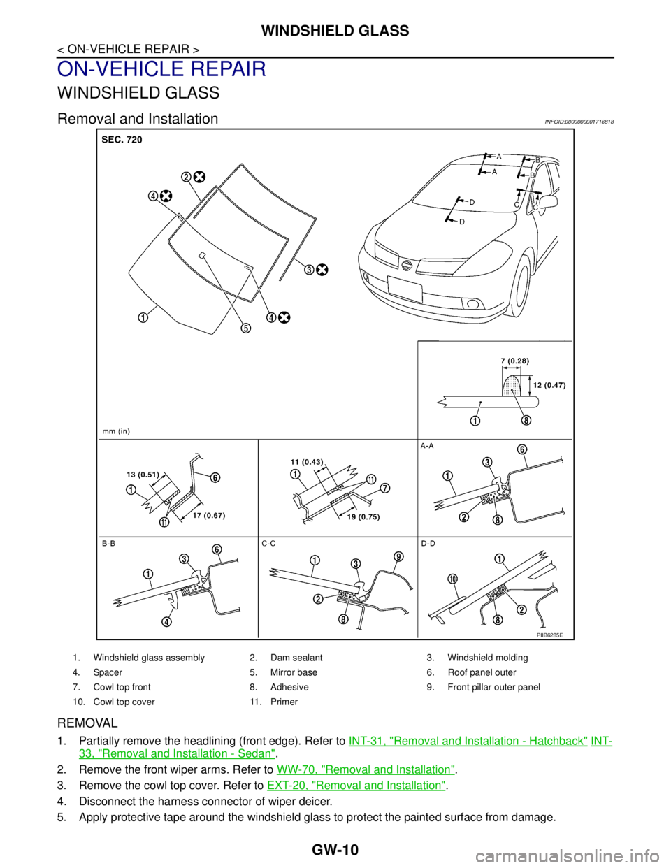
Removal and InstallationINFOID:0000000001716818
REMOVAL
1. Partially remove the headlining (front edge). Refer to INT-31, "Removal and Installation - Hatchback" INT-
33, "Removal and Installation - Sedan".
2. Remove the front wiper arms. Refer to WW-70, "
Removal and Installation".
3. Remove the cowl top cover. Refer to EXT-20, "
Removal and Installation".
4. Disconnect the harness connector of wiper deicer.
5. Apply protective tape around the windshield glass to protect the painted surface from damage.
PIIB6285E
1. Windshield glass assembly 2. Dam sealant 3. Windshield molding
4. Spacer 5. Mirror base 6. Roof panel outer
7. Cowl top front 8. Adhesive 9. Front pillar outer panel
10. Cowl top cover 11. Primer