rear window NISSAN TIIDA 2007 Service Owner's Manual
[x] Cancel search | Manufacturer: NISSAN, Model Year: 2007, Model line: TIIDA, Model: NISSAN TIIDA 2007Pages: 5883, PDF Size: 78.95 MB
Page 567 of 5883
DEF-16
< COMPONENT DIAGNOSIS >
DRIVER SIDE DOOR MIRROR DEFOGGER
DRIVER SIDE DOOR MIRROR DEFOGGER
DescriptionINFOID:0000000001697559
Heats the heating wire with the power supply from the rear window defogger relay to prevent the door mirror
from fogging up.
Component Function CheckINFOID:0000000001697560
1. CHECK DOOR MIRROR DEFOGGER LH
Check that heating wire of door mirror defogger LH is heated when turning the rear window defogger switch
ON.
Is the inspection result normal?
YES >> Door mirror defogger is OK.
NO >> Refer to DEF-16, "
Diagnosis Procedure".
Diagnosis ProcedureINFOID:0000000001697561
1. CHECK POWER SUPPLY CIRCUIT
1. Turn ignition switch OFF.
2. Disconnect door mirror LH.
3. Turn ignition switch ON.
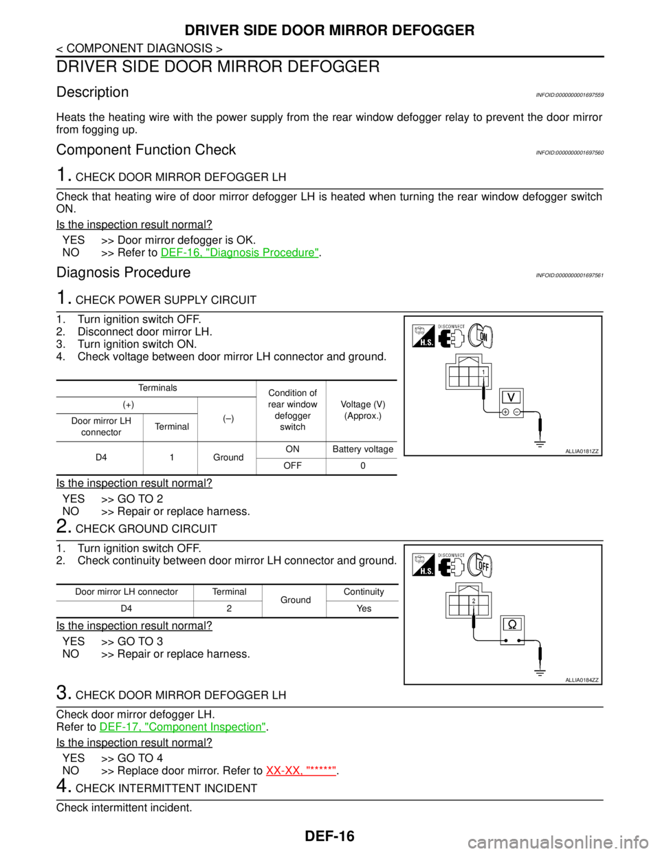
4. Check voltage between door mirror LH connector and ground.
Is the inspection result normal?
YES >> GO TO 2
NO >> Repair or replace harness.
2. CHECK GROUND CIRCUIT
1. Turn ignition switch OFF.
2. Check continuity between door mirror LH connector and ground.
Is the inspection result normal?
YES >> GO TO 3
NO >> Repair or replace harness.
3. CHECK DOOR MIRROR DEFOGGER LH
Check door mirror defogger LH.
Refer to DEF-17, "
Component Inspection".
Is the inspection result normal?
YES >> GO TO 4
NO >> Replace door mirror. Refer to XX-XX, "*****"
.
4. CHECK INTERMITTENT INCIDENT
Check intermittent incident.
Te r m i n a l s
Condition of
rear window
defogger
switchVoltage (V)
(Approx.) (+)
(–)
Door mirror LH
connectorTe r m i n a l
D4 1 GroundON Battery voltage
OFF 0
ALLIA0181ZZ
Door mirror LH connector Terminal
GroundContinuity
D4 2 Yes
ALLIA0184ZZ
Page 569 of 5883
DEF-18
< COMPONENT DIAGNOSIS >
PASSENGER SIDE DOOR MIRROR DEFOGGER
PASSENGER SIDE DOOR MIRROR DEFOGGER
DescriptionINFOID:0000000001697563
Heats the heating wire with the power supply from the rear window defogger relay to prevent the door mirror
from fogging up.
Component Function CheckINFOID:0000000001697564
1.CHECK DOOR MIRROR DEFOGGER RH
Check that the heating wire of door mirror defogger RH is heated when turning the rear window defogger
switch ON.
Is the inspection result normal?
YES >> Door mirror defogger RH is OK.
NO >> Refer to DEF-18, "
Diagnosis Procedure".
Diagnosis ProcedureINFOID:0000000001697565
1. CHECK POWER SUPPLY CIRCUIT
1. Turn ignition switch OFF.
2. Disconnect door mirror RH.
3. Turn ignition switch ON.
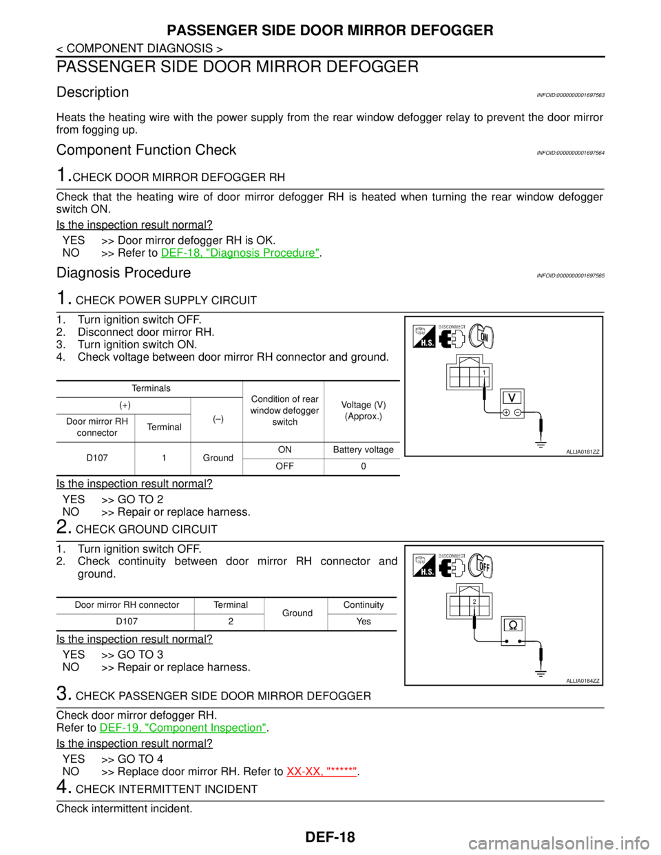
4. Check voltage between door mirror RH connector and ground.
Is the inspection result normal?
YES >> GO TO 2
NO >> Repair or replace harness.
2. CHECK GROUND CIRCUIT
1. Turn ignition switch OFF.
2. Check continuity between door mirror RH connector and
ground.
Is the inspection result normal?
YES >> GO TO 3
NO >> Repair or replace harness.
3. CHECK PASSENGER SIDE DOOR MIRROR DEFOGGER
Check door mirror defogger RH.
Refer to DEF-19, "
Component Inspection".
Is the inspection result normal?
YES >> GO TO 4
NO >> Replace door mirror RH. Refer to XX-XX, "*****"
.
4. CHECK INTERMITTENT INCIDENT
Check intermittent incident.
Te r m i n a l s
Condition of rear
window defogger
switchVoltage (V)
(Approx.) (+)
(–)
Door mirror RH
connectorTe r m i n a l
D107 1 GroundON Battery voltage
OFF 0
ALLIA0181ZZ
Door mirror RH connector Terminal
GroundContinuity
D107 2 Yes
ALLIA0184ZZ
Page 580 of 5883
REAR WINDOW DEFOGGER AND DOOR MIRROR DEFOGGER DO NOT OPER-
ATE.
DEF-29
< SYMPTOM DIAGNOSIS >
C
D
E
F
G
H
I
J
K
MA
B
DEF
N
O
P
SYMPTOM DIAGNOSIS
REAR WINDOW DEFOGGER AND DOOR MIRROR DEFOGGER DO NOT
OPERATE.
Diagnosis ProcedureINFOID:0000000001697569
1. CHECK REAR WINDOW DEFOGGER SWITCH
Check rear window defogger switch.
Refer to DEF-14, "
Component Function Check".
Is the inspection result normal?
YES >> GO TO 2
NO >> Repair or replace the malfunctioning parts.
2. CHECK REAR WINDOW DEFOGGER RELAY
Check rear window defogger relay.
Refer to DEF-12, "
Component Function Check".
Is the inspection result normal?
YES >> Refer to XX-XX, "*****".
NO >> Repair or replace the malfunctioning parts.
Page 581 of 5883
DEF-30
< SYMPTOM DIAGNOSIS >
REAR WINDOW DEFOGGER DOES NOT OPERATE BUT BOTH OF DOOR MIR-
ROR DEFOGGER OPERATE.
REAR WINDOW DEFOGGER DOES NOT OPERATE BUT BOTH OF DOOR
MIRROR DEFOGGER OPERATE.
Diagnosis ProcedureINFOID:0000000001697570
1. CHECK REAR WINDOW DEFOGGER POWER SUPPLY AND GROUND CIRCUIT
Check rear window defogger power supply and ground circuit.
Refer to DEF-14, "
Component Function Check".
Is the inspection result normal?
YES >> Refer to XX-XX, "*****".
NO >> Repair or replace the malfunctioning parts.
Page 582 of 5883
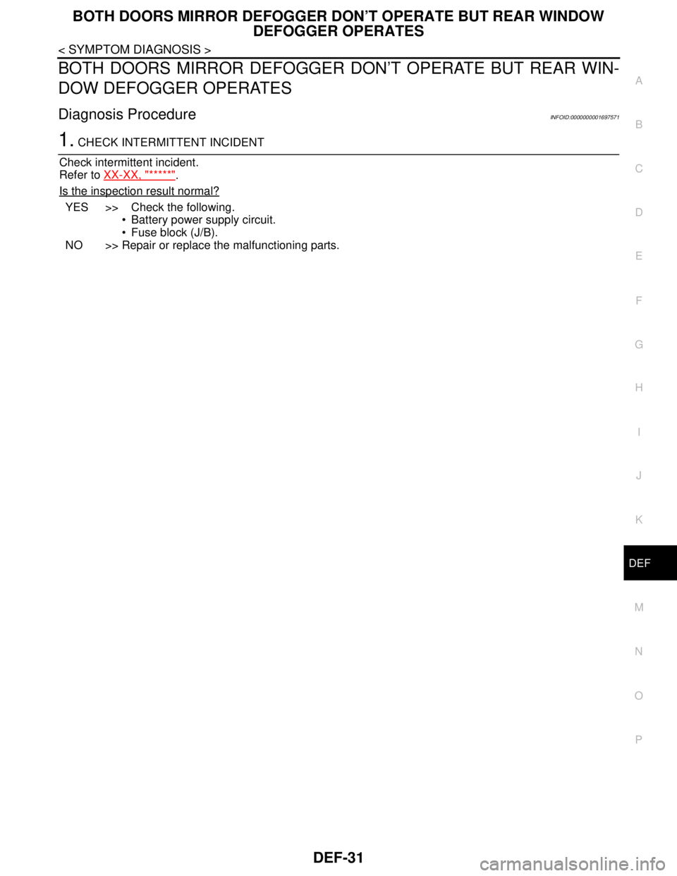
BOTH DOORS MIRROR DEFOGGER DON’T OPERATE BUT REAR WINDOW
DEFOGGER OPERATES
DEF-31
< SYMPTOM DIAGNOSIS >
C
D
E
F
G
H
I
J
K
MA
B
DEF
N
O
P
BOTH DOORS MIRROR DEFOGGER DON’T OPERATE BUT REAR WIN-
DOW DEFOGGER OPERATES
Diagnosis ProcedureINFOID:0000000001697571
1. CHECK INTERMITTENT INCIDENT
Check intermittent incident.
Refer to XX-XX, "*****"
.
Is the inspection result normal?
YES >> Check the following.
Battery power supply circuit.
Fuse block (J/B).
NO >> Repair or replace the malfunctioning parts.
Page 585 of 5883
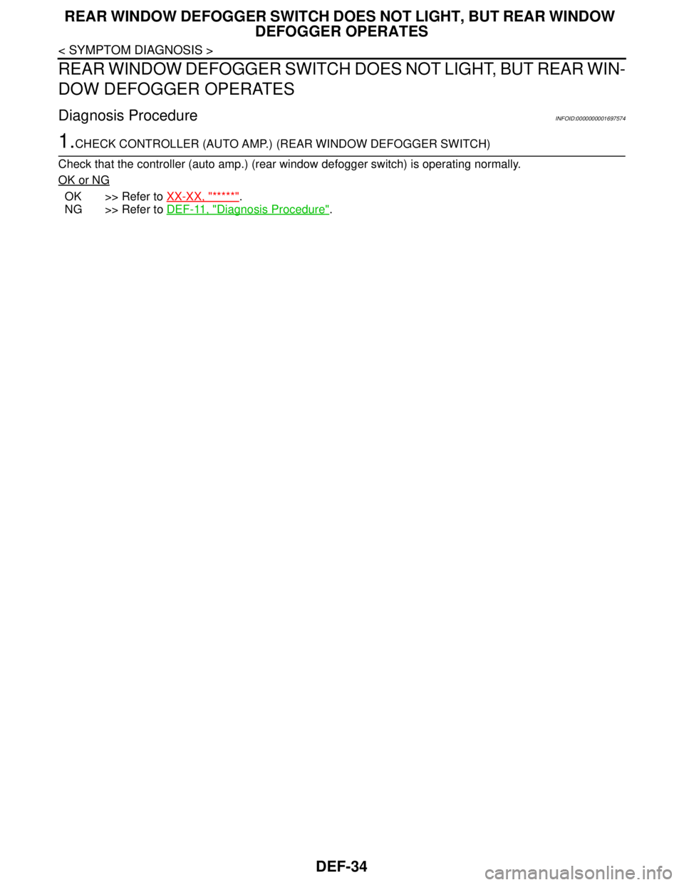
DEF-34
< SYMPTOM DIAGNOSIS >
REAR WINDOW DEFOGGER SWITCH DOES NOT LIGHT, BUT REAR WINDOW
DEFOGGER OPERATES
REAR WINDOW DEFOGGER SWITCH DOES NOT LIGHT, BUT REAR WIN-
DOW DEFOGGER OPERATES
Diagnosis ProcedureINFOID:0000000001697574
1.CHECK CONTROLLER (AUTO AMP.) (REAR WINDOW DEFOGGER SWITCH)
Check that the controller (auto amp.) (rear window defogger switch) is operating normally.
OK or NG
OK >> Refer to XX-XX, "*****".
NG >> Refer to DEF-11, "
Diagnosis Procedure".
Page 611 of 5883

DLK-22
< FUNCTION DIAGNOSIS >[WITH I-KEY, WITHOUT SUPER LOCK]
DOOR LOCK FUNCTION
DOOR LOCK AND UNLOCK SWITCH : Component Parts Location
INFOID:0000000001396464
ALKIA0810ZZ
1. BCM M18, M19, M20
(view with glove box removed)2. Intelligent Key unit M52 3. Front door switch (driver side) B34
(Passenger side) B27
4. Front door lock actuator (driver side) D14
(Passenger side) D114
Door unlock sensor (driver side) D145. Rear door switch LH B71
RH B536. Rear door lock actuator LH D205
RH D305
7. Key switch and ignition knob switch (A/T)
M328. Key switch and ignition knob switch
(M/T) M329. Main power window and door lock/
unlock switch D7, D8
10. Back door lock assembly (back door switch)
D405 (hatchback view with back door open)11. Back door opener switch (hatch-
back) D40812. Trunk lid opener switch (sedan) B61
Page 639 of 5883

DLK-50
< FUNCTION DIAGNOSIS >[WITH I-KEY, WITHOUT SUPER LOCK]
DIAGNOSIS SYSTEM (BCM)
DIAGNOSIS SYSTEM (BCM)
COMMON ITEM
COMMON ITEM : CONSULT-III Function (BCM - COMMON ITEM)INFOID:0000000001396502
APPLICATION ITEM
CONSULT-III performs the following functions via CAN communication with BCM.
SYSTEM APPLICATION
BCM can perform the following functions for each system.
NOTE:
It can perform the diagnosis modes except the following for all sub system selection items.
DOOR LOCK
DOOR LOCK : CONSULT-III Function (BCM - DOOR LOCK)INFOID:0000000001396503
BCM CONSULT-III FUNCTION
CONSULT-III performs the following functions via CAN communication with BCM.
Diagnosis mode Function Description
WORK SUPPORT Changes the setting for each system function.
SELF-DIAG RESULTS Displays the diagnosis results judged by BCM. Refer to XX-XX, "*****"
.
CAN DIAG SUPPORT MNTR Monitors the reception status of CAN communication viewed from BCM.
DATA MONITOR The BCM input/output signals are displayed.
ACTIVE TEST The signals used to activate each device are forcibly supplied from BCM.
ECU IDENTIFICATION The BCM part number is displayed.
CONFIGURATION Enables to read and save the vehicle specification.
Enables to write the vehicle specification when replacing BCM.
System Sub system selection itemDiagnosis mode
WORK SUPPORT DATA MONITOR ACTIVE TEST
—BCM×
Door lock DOOR LOCK×××
Rear window defogger REAR DEFOGGER××
Warning chime BUZZER××
Interior room lamp timer INT LAMP×××
Remote keyless entry system MULTI REMOTE ENT×××
Exterior lamp HEAD LAMP×××
Wiper and washer WIPER×××
Turn signal and hazard warning lamps FLASHER××
Air conditioner AIR CONDITONER×
Intelligent Key system INTELLIGENT KEY×
Combination switch COMB SW×
Immobilizer IMMU××
Interior room lamp battery saver BATTERY SAVER×××
Trunk open TRUNK×
Vehicle security system THEFT ALM×××
Signal buffer system SIGNAL BUFFER××
PTC heater system PTC HEATER××
Page 813 of 5883

DLK-224
< REMOVAL AND INSTALLATION >[WITH I-KEY, WITHOUT SUPER LOCK]
DOOR
1. Open and support the back door.
2. Slightly loosen the hinge nuts.
3. Reposition the door as necessary and tighten the nuts.
4. Confirm the adjustment. Repeat as necessary to obtain the desired fit.
Striker Adjustment
1. Back door assembly 2. Back door hinge 3. Tail lamp assembly
4. Back window glass 5. Roof 6. Rear pillar
A. 6.0 ± 1.0 mm (0.24 ± 0.04 in) B. -0.5 ± 1.0 mm (-0.02 ± 0.04 in) C. 5.0 ± 1.2 mm (0.20 ± 0.05 in)
D. 0.0 ± 1.5 mm (0.0 ± 0.06 in) E. 5.0 ± 2.3 mm ( 0.20 ± 0.9 in) F. 2.7 +1.6 -2.1 mm (0.11 + 0.06 - 0.08 in)
G. 5.0 ± 1.2 mm ( 0.20 ± 0.05 in) H. 0.0 ± 1.5 mm (0.0 ± 0.06 in)
LIIA2668E
Page 819 of 5883

DLK-230
< REMOVAL AND INSTALLATION >[WITH I-KEY, WITHOUT SUPER LOCK]
FRONT DOOR LOCK
FRONT DOOR LOCK
Component Parts LocationINFOID:0000000001315860
Removal and InstallationINFOID:0000000001315861
REMOVAL
1. Remove front door finisher. Refer to INT-13, "Removal and Installation" .
2. Fully close front door window.
3. Remove the front door sealing screen.
NOTE:
If sealing screen is reused, cut butyl tape in a way that leaves it on the sealing screen.
4. Remove front door rear glass run channel. Refer to GW-14, "
Removal and Installation" .
5. Remove the cables from the holder.
6. Remove inside handle bolt, and slide the handle toward the rear
of the vehicle. disengage the handle from the door panel, and
remove the inside handle.
7. Disengage the handle from the door panel, and remove the inside handle.
1. Front door 2. Inside handle 3. Inside handle cable
4. Door lock assembly 5. Outside handle cable 6. TORX bolt (T30)
7. Key cylinder connecting rod 8. Grommet 9. TORX bolt (T30)
10. Rear gasket 11. Door key cylinder assembly
(Driver's side)
Outside handle escutcheon
(passenger's side)12. Outside handle
13. Front gasket 14. Lock knob cable 15. Holder
16. Outside handle bracket
PIIB6523E
PIIB6524E