water pump NISSAN TIIDA 2007 Service Owner's Guide
[x] Cancel search | Manufacturer: NISSAN, Model Year: 2007, Model line: TIIDA, Model: NISSAN TIIDA 2007Pages: 5883, PDF Size: 78.95 MB
Page 2373 of 5883
EC-1024
< SYMPTOM DIAGNOSIS >[MR18DE]
ENGINE CONTROL SYSTEM
SYMPTOM DIAGNOSIS
ENGINE CONTROL SYSTEM
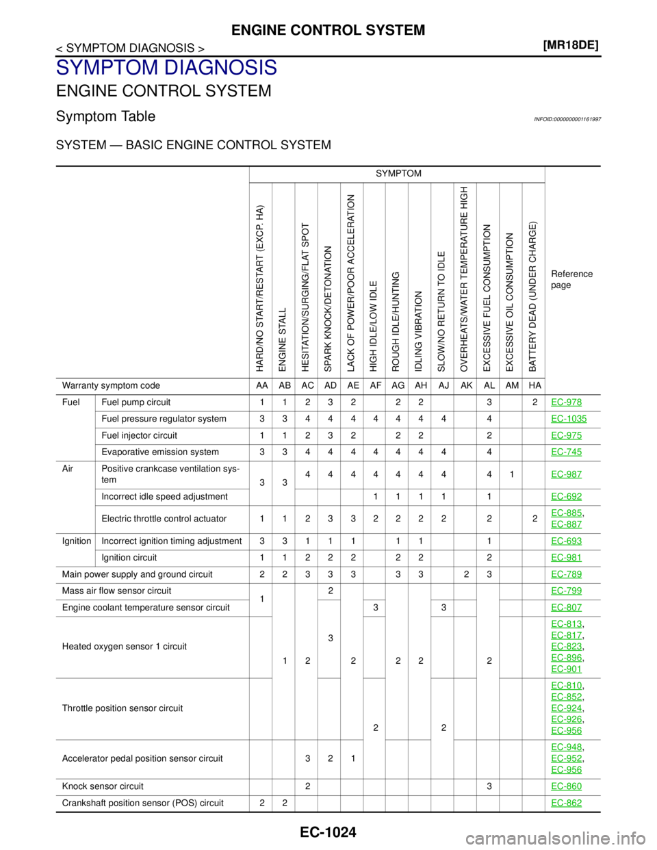
Symptom TableINFOID:0000000001161997
SYSTEM — BASIC ENGINE CONTROL SYSTEM
SYMPTOM
Reference
page
HARD/NO START/RESTART (EXCP. HA)
ENGINE STALL
HESITATION/SURGING/FLAT SPOT
SPARK KNOCK/DETONATION
LACK OF POWER/POOR ACCELERATION
HIGH IDLE/LOW IDLE
ROUGH IDLE/HUNTING
IDLING VIBRATION
SLOW/NO RETURN TO IDLE
OVERHEATS/WATER TEMPERATURE HIGH
EXCESSIVE FUEL CONSUMPTION
EXCESSIVE OIL CONSUMPTION
BATTERY DEAD (UNDER CHARGE)
Warranty symptom code AA AB AC AD AE AF AG AH AJ AK AL AM HA
Fuel Fuel pump circuit 11232 22 3 2EC-978
Fuel pressure regulator system 334444444 4EC-1035
Fuel injector circuit 11232 22 2EC-975
Evaporative emission system 334444444 4EC-745
Air Positive crankcase ventilation sys-
tem
334444444 41EC-987
Incorrect idle speed adjustment 1 1 1 1 1EC-692
Electric throttle control actuator 112332222 2 2EC-885,
EC-887
IgnitionIncorrect ignition timing adjustment33111 11 1EC-693
Ignition circuit 11222 22 2EC-981
Main power supply and ground circuit 22333 33 23EC-789
Mass air flow sensor circuit
1
122
222 2EC-799
Engine coolant temperature sensor circuit
333EC-807
Heated oxygen sensor 1 circuitEC-813
,
EC-817
,
EC-823
,
EC-896
,
EC-901
Throttle position sensor circuit
22EC-810
,
EC-852
,
EC-924
,
EC-926
,
EC-956
Accelerator pedal position sensor circuit 3 2 1EC-948
,
EC-952
,
EC-956
Knock sensor circuit 2 3EC-860
Crankshaft position sensor (POS) circuit 2 2EC-862
Page 2376 of 5883
ENGINE CONTROL SYSTEM
EC-1027
< SYMPTOM DIAGNOSIS >[MR18DE]
C
D
E
F
G
H
I
J
K
L
MA
EC
N
P O
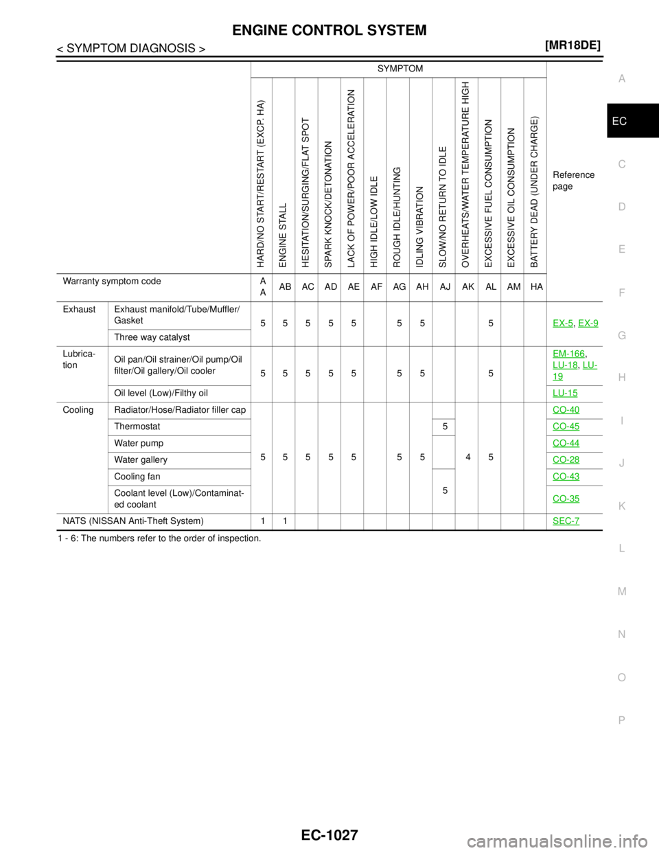
1 - 6: The numbers refer to the order of inspection.Exhaust Exhaust manifold/Tube/Muffler/
Gasket
55555 55 5EX-5
, EX-9
Three way catalyst
Lubrica-
tionOil pan/Oil strainer/Oil pump/Oil
filter/Oil gallery/Oil cooler
55555 55 5EM-166
,
LU-18
, LU-
19
Oil level (Low)/Filthy oilLU-15
Cooling Radiator/Hose/Radiator filler cap
55555 55 45CO-40
Thermostat 5CO-45
Water pumpCO-44
Water galleryCO-28
Cooling fan
5CO-43
Coolant level (Low)/Contaminat-
ed coolantCO-35
NATS (NISSAN Anti-Theft System) 1 1SEC-7
SYMPTOM
Reference
page
HARD/NO START/RESTART (EXCP. HA)
ENGINE STALL
HESITATION/SURGING/FLAT SPOT
SPARK KNOCK/DETONATION
LACK OF POWER/POOR ACCELERATION
HIGH IDLE/LOW IDLE
ROUGH IDLE/HUNTING
IDLING VIBRATION
SLOW/NO RETURN TO IDLE
OVERHEATS/WATER TEMPERATURE HIGH
EXCESSIVE FUEL CONSUMPTION
EXCESSIVE OIL CONSUMPTION
BATTERY DEAD (UNDER CHARGE)
Warranty symptom code A
AAB AC AD AE AF AG AH AJ AK AL AM HA
Page 2398 of 5883
INSPECTION AND ADJUSTMENT
EC-1049
< BASIC INSPECTION >[K9K]
C
D
E
F
G
H
I
J
K
L
MA
EC
N
P O
>> INSPECTION END
6.CHECK ENGINE CONDITION
Check that the oil level is correct and that the engine coolant temperature is normal operation tempera-
ture.60°C (140°F)
Engine running at idle speed.
- Select “HIGH PRES CIRCUIT LEAK TEST” in “ACTIVE TEST” mode with CONSULT-III.
- Engine will perform 4 acceleration cycles.
- Select “DATA MONITOR” mode with CONSULT-III.
- Check that the “RAIL PRES SET” and “RAIL PRESSURE” indication.
- Does “RAIL PRESSURE” follow “RAIL PRES SET” at during the phase of 4 acceleration cycles?
Is the inspection result normal?
YES >> GO TO 22.
NO >> GO TO 7.
7.CHECK ENGINE COOLANT TEMPERATURE AND FUEL TEMPERATURE
1. Select “DATA MONITOR” mode with CONSULT-III.
2. Check that the “FUEL TEMP” indication when operating at idle speed is between 60 - 80°C (140 - 176°F)
3. Check that the “WATER TEMP” indication is between 80 - 90°C (176 - 194°F)
NOTE:
When the fuel temperature is above 136°C (277°F), the maximum rail pressure is reduced to protect the
plastic pipes.
When the coolant temperature is above 100°C (212°F), the maximum rail pressure is reduced to protect the
engine.
Are the
“FUEL TEMP” and “WATER TEMP” within the reference value range?
YES >> GO TO 8.
NO >> Check the fuel pump temperature sensor (Refer to EC-1137, "
Component Inspection") or engine
coolant temperature sensor (Refer to EC-1133, "
Component Inspection").
8.CHECK HIGH PRESSURE SUPPLY PUMP (VOLUMETRIC CONTROL VALVE) POWER SUPPLY
1. Turn ignition switch OFF.
2. Disconnect high pressure supply pump (volumetric control valve) harness connector.
3. Turn ignition switch ON.
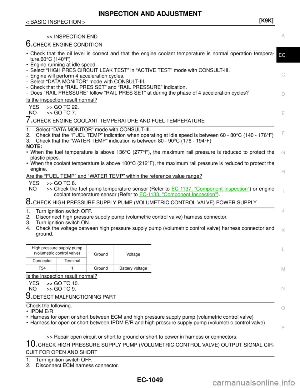
4. Check the voltage between high pressure supply pump (volumetric control valve) harness connector and
ground.
Is the inspection result normal?
YES >> GO TO 10.
NO >> GO TO 9.
9.DETECT MALFUNCTIONING PART
Check the following.
IPDM E/R
Harness for open or short between ECM and high pressure supply pump (volumetric control valve)
Harness for open or short between IPDM E/R and high pressure supply pump (volumetric control valve)
>> Repair open circuit or short to ground or short to power in harness or connectors.
10.CHECK HIGH PRESSURE SUPPLY PUMP (VOLUMETRIC CONTROL VALVE) OUTPUT SIGNAL CIR-
CUIT FOR OPEN AND SHORT
1. Turn ignition switch OFF.
2. Disconnect ECM harness connector.
High pressure supply pump
(volumetric control valve)
Ground Voltage
Connector Terminal
F54 1 Ground Battery voltage
Page 2419 of 5883
EC-1070
< FUNCTION DIAGNOSIS >[K9K]
TURBOCHARGER BOOST CONTROL
TURBOCHARGER BOOST CONTROL
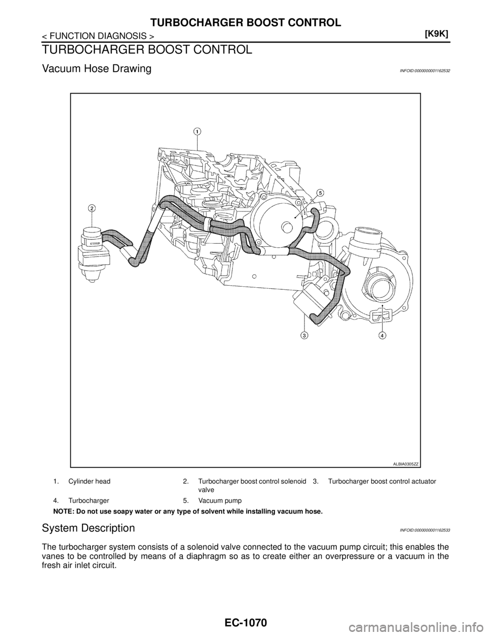
Vacuum Hose DrawingINFOID:0000000001162532
System DescriptionINFOID:0000000001162533
The turbocharger system consists of a solenoid valve connected to the vacuum pump circuit; this enables the
vanes to be controlled by means of a diaphragm so as to create either an overpressure or a vacuum in the
fresh air inlet circuit.
1. Cylinder head 2. Turbocharger boost control solenoid
valve3. Turbocharger boost control actuator
4. Turbocharger 5. Vacuum pump
NOTE: Do not use soapy water or any type of solvent while installing vacuum hose.
ALBIA0305ZZ
Page 2573 of 5883
EC-1224
< ECU DIAGNOSIS >[K9K]
ECM
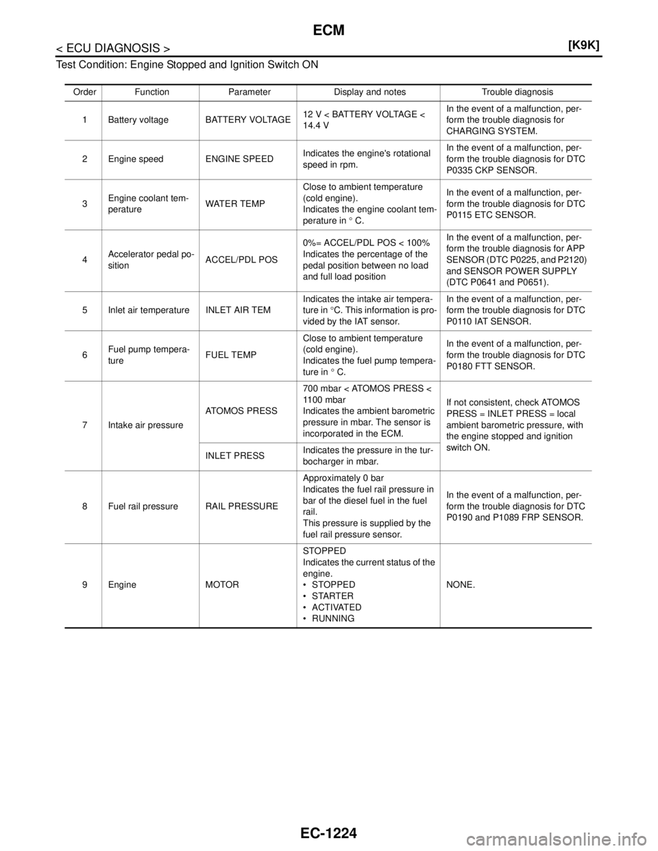
Test Condition: Engine Stopped and Ignition Switch ON
Order Function Parameter Display and notes Trouble diagnosis
1 Battery voltage BATTERY VOLTAGE12 V < BATTERY VOLTAGE <
14.4 VIn the event of a malfunction, per-
form the trouble diagnosis for
CHARGING SYSTEM.
2 Engine speed ENGINE SPEEDIndicates the engine's rotational
speed in rpm.In the event of a malfunction, per-
form the trouble diagnosis for DTC
P0335 CKP SENSOR.
3Engine coolant tem-
peratureWATER TEMPClose to ambient temperature
(cold engine).
Indicates the engine coolant tem-
perature in ° C.In the event of a malfunction, per-
form the trouble diagnosis for DTC
P0115 ETC SENSOR.
4Accelerator pedal po-
sitionACCEL/PDL POS0%= ACCEL/PDL POS < 100%
Indicates the percentage of the
pedal position between no load
and full load positionIn the event of a malfunction, per-
form the trouble diagnosis for APP
SENSOR (DTC P0225, and P2120)
and SENSOR POWER SUPPLY
(DTC P0641 and P0651).
5 Inlet air temperature INLET AIR TEMIndicates the intake air tempera-
ture in °C. This information is pro-
vided by the IAT sensor.In the event of a malfunction, per-
form the trouble diagnosis for DTC
P0110 IAT SENSOR.
6Fuel pump tempera-
tureFUEL TEMPClose to ambient temperature
(cold engine).
Indicates the fuel pump tempera-
ture in ° C.In the event of a malfunction, per-
form the trouble diagnosis for DTC
P0180 FTT SENSOR.
7 Intake air pressureATOMOS PRESS700 mbar < ATOMOS PRESS <
11 0 0 m b a r
Indicates the ambient barometric
pressure in mbar. The sensor is
incorporated in the ECM.If not consistent, check ATOMOS
PRESS = INLET PRESS = local
ambient barometric pressure, with
the engine stopped and ignition
switch ON.
INLET PRESSIndicates the pressure in the tur-
bocharger in mbar.
8 Fuel rail pressure RAIL PRESSUREApproximately 0 bar
Indicates the fuel rail pressure in
bar of the diesel fuel in the fuel
rail.
This pressure is supplied by the
fuel rail pressure sensor.In the event of a malfunction, per-
form the trouble diagnosis for DTC
P0190 and P1089 FRP SENSOR.
9Engine MOTORSTOPPED
Indicates the current status of the
engine.
STOPPED
STARTER
ACTIVATED
RUNNINGNONE.
Page 2574 of 5883
ECM
EC-1225
< ECU DIAGNOSIS >[K9K]
C
D
E
F
G
H
I
J
K
L
MA
EC
N
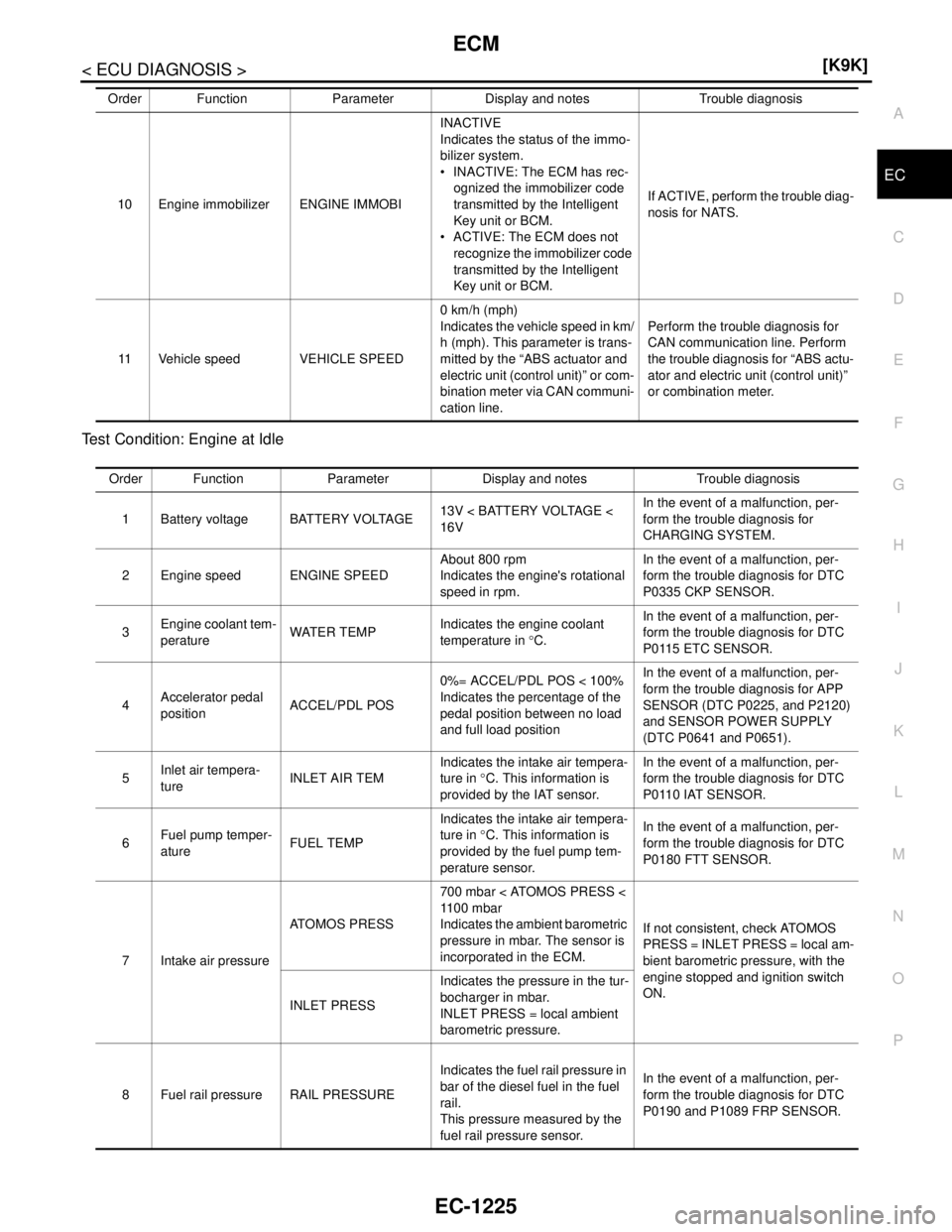
P O Test Condition: Engine at Idle
10 Engine immobilizer ENGINE IMMOBIINACTIVE
Indicates the status of the immo-
bilizer system.
INACTIVE: The ECM has rec-
ognized the immobilizer code
transmitted by the Intelligent
Key unit or BCM.
ACTIVE: The ECM does not
recognize the immobilizer code
transmitted by the Intelligent
Key unit or BCM.If ACTIVE, perform the trouble diag-
nosis for NATS.
11 Vehicle speed VEHICLE SPEED0 km/h (mph)
Indicates the vehicle speed in km/
h (mph). This parameter is trans-
mitted by the “ABS actuator and
electric unit (control unit)” or com-
bination meter via CAN communi-
cation line.Perform the trouble diagnosis for
CAN communication line. Perform
the trouble diagnosis for “ABS actu-
ator and electric unit (control unit)”
or combination meter. Order Function Parameter Display and notes Trouble diagnosis
Order Function Parameter Display and notes Trouble diagnosis
1 Battery voltage BATTERY VOLTAGE13V < BATTERY VOLTAGE <
16VIn the event of a malfunction, per-
form the trouble diagnosis for
CHARGING SYSTEM.
2 Engine speed ENGINE SPEEDAbout 800 rpm
Indicates the engine's rotational
speed in rpm.In the event of a malfunction, per-
form the trouble diagnosis for DTC
P0335 CKP SENSOR.
3Engine coolant tem-
peratureWATER TEMPIndicates the engine coolant
temperature in °C.In the event of a malfunction, per-
form the trouble diagnosis for DTC
P0115 ETC SENSOR.
4Accelerator pedal
positionACCEL/PDL POS0%= ACCEL/PDL POS < 100%
Indicates the percentage of the
pedal position between no load
and full load positionIn the event of a malfunction, per-
form the trouble diagnosis for APP
SENSOR (DTC P0225, and P2120)
and SENSOR POWER SUPPLY
(DTC P0641 and P0651).
5Inlet air tempera-
tureINLET AIR TEMIndicates the intake air tempera-
ture in °C. This information is
provided by the IAT sensor.In the event of a malfunction, per-
form the trouble diagnosis for DTC
P0110 IAT SENSOR.
6Fuel pump temper-
atureFUEL TEMPIndicates the intake air tempera-
ture in °C. This information is
provided by the fuel pump tem-
perature sensor.In the event of a malfunction, per-
form the trouble diagnosis for DTC
P0180 FTT SENSOR.
7 Intake air pressureATOMOS PRESS700 mbar < ATOMOS PRESS <
11 0 0 m b a r
Indicates the ambient barometric
pressure in mbar. The sensor is
incorporated in the ECM.If not consistent, check ATOMOS
PRESS = INLET PRESS = local am-
bient barometric pressure, with the
engine stopped and ignition switch
ON.
INLET PRESSIndicates the pressure in the tur-
bocharger in mbar.
INLET PRESS = local ambient
barometric pressure.
8 Fuel rail pressure RAIL PRESSUREIndicates the fuel rail pressure in
bar of the diesel fuel in the fuel
rail.
This pressure measured by the
fuel rail pressure sensor.In the event of a malfunction, per-
form the trouble diagnosis for DTC
P0190 and P1089 FRP SENSOR.
Page 2576 of 5883
ECM
EC-1227
< ECU DIAGNOSIS >[K9K]
C
D
E
F
G
H
I
J
K
L
MA
EC
N
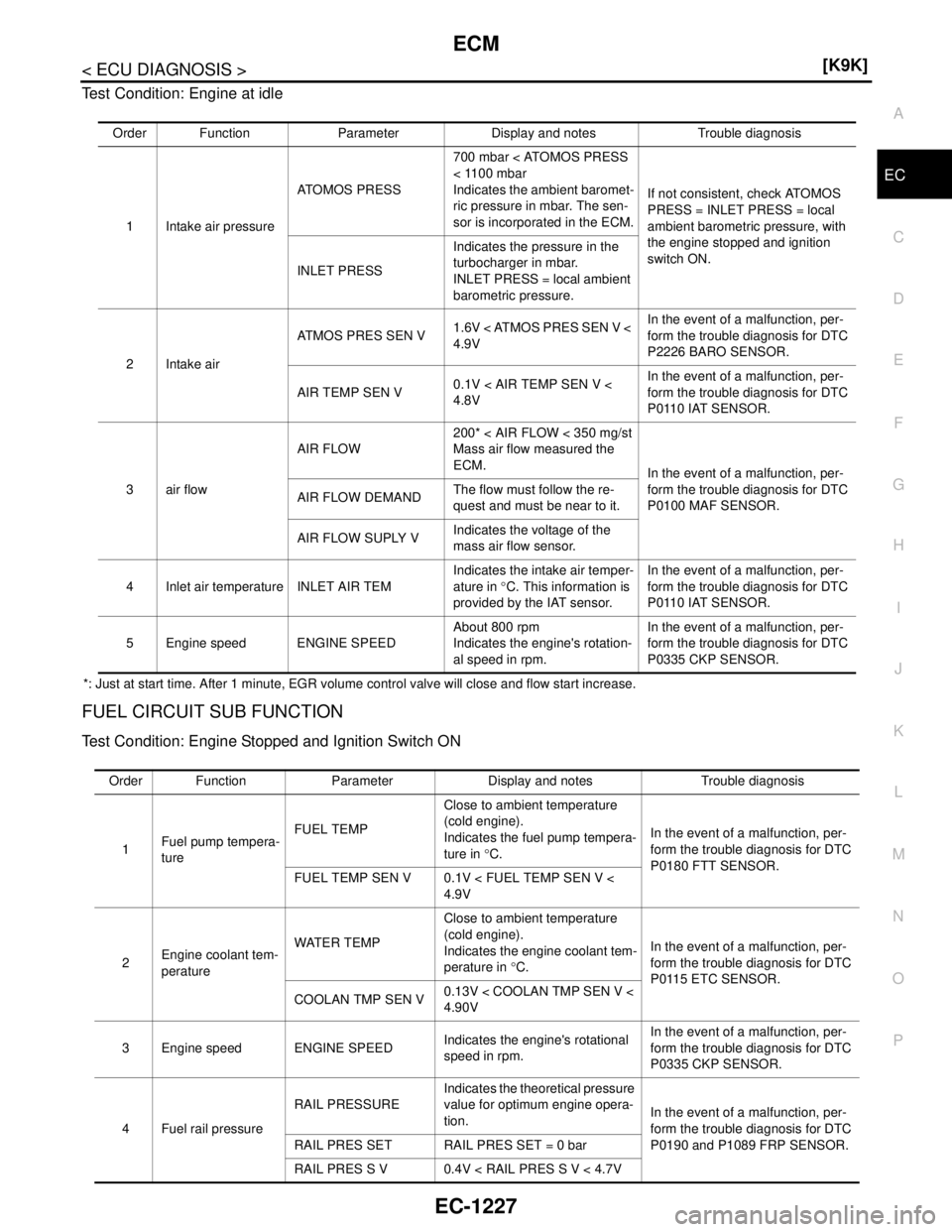
P O Test Condition: Engine at idle
*: Just at start time. After 1 minute, EGR volume control valve will close and flow start increase.
FUEL CIRCUIT SUB FUNCTION
Test Condition: Engine Stopped and Ignition Switch ON
Order Function Parameter Display and notes Trouble diagnosis
1 Intake air pressureATOMOS PRESS700 mbar < ATOMOS PRESS
< 1100 mbar
Indicates the ambient baromet-
ric pressure in mbar. The sen-
sor is incorporated in the ECM.If not consistent, check ATOMOS
PRESS = INLET PRESS = local
ambient barometric pressure, with
the engine stopped and ignition
switch ON.
INLET PRESSIndicates the pressure in the
turbocharger in mbar.
INLET PRESS = local ambient
barometric pressure.
2 Intake airATMOS PRES SEN V1.6V < ATMOS PRES SEN V <
4.9VIn the event of a malfunction, per-
form the trouble diagnosis for DTC
P2226 BARO SENSOR.
AIR TEMP SEN V0.1V < AIR TEMP SEN V <
4.8VIn the event of a malfunction, per-
form the trouble diagnosis for DTC
P0110 IAT SENSOR.
3air flowAIR FLOW200* < AIR FLOW < 350 mg/st
Mass air flow measured the
ECM.
In the event of a malfunction, per-
form the trouble diagnosis for DTC
P0100 MAF SENSOR. AIR FLOW DEMANDThe flow must follow the re-
quest and must be near to it.
AIR FLOW SUPLY VIndicates the voltage of the
mass air flow sensor.
4 Inlet air temperature INLET AIR TEMIndicates the intake air temper-
ature in °C. This information is
provided by the IAT sensor.In the event of a malfunction, per-
form the trouble diagnosis for DTC
P0110 IAT SENSOR.
5 Engine speed ENGINE SPEEDAbout 800 rpm
Indicates the engine's rotation-
al speed in rpm.In the event of a malfunction, per-
form the trouble diagnosis for DTC
P0335 CKP SENSOR.
Order Function Parameter Display and notes Trouble diagnosis
1Fuel pump tempera-
tureFUEL TEMPClose to ambient temperature
(cold engine).
Indicates the fuel pump tempera-
ture in °C.In the event of a malfunction, per-
form the trouble diagnosis for DTC
P0180 FTT SENSOR.
FUEL TEMP SEN V 0.1V < FUEL TEMP SEN V <
4.9V
2Engine coolant tem-
peratureWATER TEMPClose to ambient temperature
(cold engine).
Indicates the engine coolant tem-
perature in °C.In the event of a malfunction, per-
form the trouble diagnosis for DTC
P0115 ETC SENSOR.
COOLAN TMP SEN V0.13V < COOLAN TMP SEN V <
4.90V
3 Engine speed ENGINE SPEEDIndicates the engine's rotational
speed in rpm.In the event of a malfunction, per-
form the trouble diagnosis for DTC
P0335 CKP SENSOR.
4 Fuel rail pressureRAIL PRESSUREIndicates the theoretical pressure
value for optimum engine opera-
tion.In the event of a malfunction, per-
form the trouble diagnosis for DTC
P0190 and P1089 FRP SENSOR. RAIL PRES SET RAIL PRES SET = 0 bar
RAIL PRES S V 0.4V < RAIL PRES S V < 4.7V
Page 2577 of 5883
EC-1228
< ECU DIAGNOSIS >[K9K]
ECM
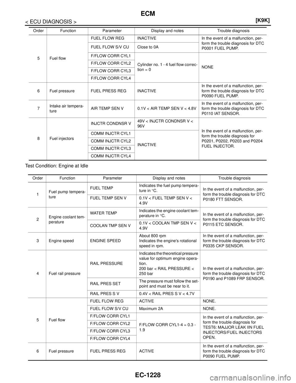
Test Condition: Engine at Idle
5 Fuel flowFUEL FLOW REG INACTIVE In the event of a malfunction, per-
form the trouble diagnosis for DTC
P0001 FUEL PUMP. FUEL FLOW S/V CU Close to 0A
F/FLOW CORR CYL1
Cylinder no. 1 - 4 fuel flow correc-
tion = 0NONE F/FLOW CORR CYL2
F/FLOW CORR CYL3
F/FLOW CORR CYL4
6 Fuel pressure FUEL PRESS REG INACTIVEIn the event of a malfunction, per-
form the trouble diagnosis for DTC
P0090 FUEL PUMP.
7Intake air tempera-
tureAIR TEMP SEN V 0.1V < AIR TEMP SEN V < 4.8VIn the event of a malfunction, per-
form the trouble diagnosis for DTC
P0110 IAT SENSOR.
8 Fuel injectorsINJCTR CONDNSR V49V < INJCTR CONDNSR V <
96V
In the event of a malfunction, per-
form the trouble diagnosis for
P0201, P0202, P0203 and P0204
FUEL INJECTOR. COMM INJCTR CYL1
INACTIVE COMM INJCTR CYL2
COMM INJCTR CYL3
COMM INJCTR CYL4 Order Function Parameter Display and notes Trouble diagnosis
Order Function Parameter Display and notes Trouble diagnosis
1Fuel pump tempera-
tureFUEL TEMPIndicates the fuel pump tempera-
ture in °C.In the event of a malfunction, per-
form the trouble diagnosis for DTC
P0180 FTT SENSOR. FUEL TEMP SEN V 0.1V < FUEL TEMP SEN V <
4.9V
2Engine coolant tem-
peratureWATER TEMPIndicates the engine coolant tem-
perature in °C.In the event of a malfunction, per-
form the trouble diagnosis for DTC
P0115 ETC SENSOR.
COOLAN TMP SEN V0.1V < COOLAN TMP SEN V <
4.9V
3 Engine speed ENGINE SPEEDAbout 800 rpm
Indicates the engine's rotational
speed in rpm.In the event of a malfunction, per-
form the trouble diagnosis for DTC
P0335 CKP SENSOR.
4 Fuel rail pressureRAIL PRESSUREIndicates the theoretical pressure
value for optimum engine opera-
tion.
200 bar < RAIL PRESSURE <
250 barIn the event of a malfunction, per-
form the trouble diagnosis for DTC
P0190 and P1089 FRP SENSOR.
RAIL PRES SETThe pressure must follow the set-
point and must be near to it.
RAIL PRES S V 0.4V < RAIL PRES S V < 4.7V
5 Fuel flowFUEL FLOW REG ACTIVE NONE.
FUEL FLOW S/V CU Maximum 2A NONE.
F/FLOW CORR CYL1
F/FLOW CORR CYL1-4 = 0.3 -
1.9In the event of a malfunction, per-
form the trouble diagnosis for
TEST6: MAJJOR LEAK IIN FUEL
INJECTORS/FUEL INJECTORS
OPEN. F/FLOW CORR CYL2
F/FLOW CORR CYL3
F/FLOW CORR CYL4
6 Fuel pressure FUEL PRESS REG ACTIVEIn the event of a malfunction, per-
form the trouble diagnosis for DTC
P0090 FUEL PUMP.
Page 2580 of 5883
ECM
EC-1231
< ECU DIAGNOSIS >[K9K]
C
D
E
F
G
H
I
J
K
L
MA
EC
N
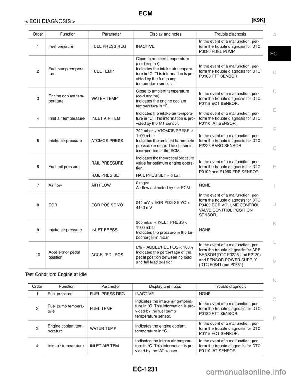
P O Test Condition: Engine at Idle
Order Function Parameter Display and notes Trouble diagnosis
1 Fuel pressure FUEL PRESS REG INACTIVEIn the event of a malfunction, per-
form the trouble diagnosis for DTC
P0090 FUEL PUMP.
2Fuel pump tempera-
tureFUEL TEMPClose to ambient temperature
(cold engine).
Indicates the intake air tempera-
ture in °C. This information is pro-
vided by the fuel pump
temperature sensor.In the event of a malfunction, per-
form the trouble diagnosis for DTC
P0180 FTT SENSOR.
3Engine coolant tem-
peratureWATER TEMPClose to ambient temperature
(cold engine).
Indicates the engine coolant
temperature in °C. In the event of a malfunction, per-
form the trouble diagnosis for DTC
P0115 ECT SENSOR.
4 Inlet air temperature INLET AIR TEMIndicates the intake air tempera-
ture in °C. This information is pro-
vided by the IAT sensor.In the event of a malfunction, per-
form the trouble diagnosis for DTC
P0110 IAT SENSOR.
5 Intake air pressure ATOMOS PRESS700 mbar < ATOMOS PRESS <
1100 mbar
Indicates the ambient barometric
pressure in mbar. The sensor is
incorporated in the ECM.In the event of a malfunction, per-
form the trouble diagnosis for DTC
P2226 BARO SENSOR.
6 Fuel rail pressureRAIL PRESSUREIndicates the theoretical pressure
value for optimum engine opera-
tion.In the event of a malfunction, per-
form the trouble diagnosis for DTC
P0190 and P1089 FRP SENSOR.
RAIL PRES SET RAIL PRES SET = 0 bar.
7 Air flow AIR FLOW0 mg/st
Air flow estimated by the ECM.NONE
8 EGR EGR POS SE VO540 mV < EGR POS SE VO <
4490 mVIn the event of a malfunction, per-
form the trouble diagnosis for DTC
P0409 EGR VOLUME CONTROL
VALVE CONTROL POSITION
SENSOR.
9 Intake air pressure INLET PRESS900 mbar < INLET PRESS <
1100 mbar
Indicates the pressure in the tur-
bocharger in mbar.NONE
10Accelerator pedal
positionACCEL/PDL POS0% = ACCEL/PDL POS < 100%
Indicates the percentage of the
pedal position between no load
and full load positionIn the event of a malfunction, per-
form the trouble diagnosis for APP
SENSOR (DTC P0225, and P2120)
and SENSOR POWER SUPPLY
(DTC P0641 and P0651).
Order Function Parameter Display and notes Trouble diagnosis
1 Fuel pressure FUEL PRESS REG INACTIVE NONE
2Fuel pump tempera-
tureFUEL TEMPIndicates the intake air tempera-
ture in °C. This information is pro-
vided by the fuel pump
temperature sensor.In the event of a malfunction, per-
form the trouble diagnosis for DTC
P0180 FTT SENSOR.
3Engine coolant tem-
peratureWATER TEMPIndicates the engine coolant
temperature in °C. In the event of a malfunction, per-
form the trouble diagnosis for DTC
P0115 ECT SENSOR.
4 Inlet air temperature INLET AIR TEMIndicates the intake air tempera-
ture in °C. This information is pro-
vided by the IAT sensor.In the event of a malfunction, per-
form the trouble diagnosis for DTC
P0110 IAT SENSOR.
Page 2653 of 5883
EM-6
< SYMPTOM DIAGNOSIS >[HR16DE]
NOISE, VIBRATION AND HARSHNESS (NVH) TROUBLESHOOTING
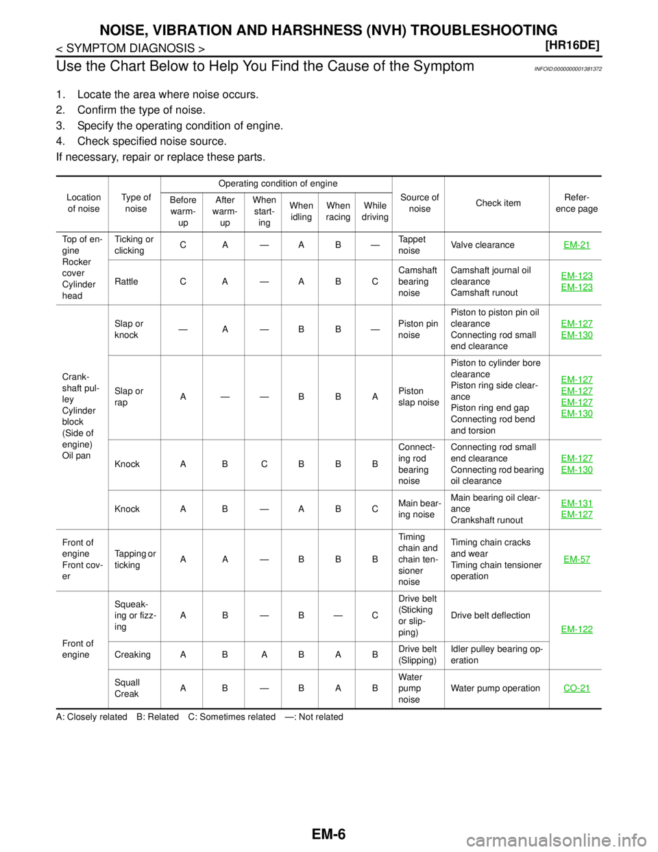
Use the Chart Below to Help You Find the Cause of the Symptom
INFOID:0000000001381372
1. Locate the area where noise occurs.
2. Confirm the type of noise.
3. Specify the operating condition of engine.
4. Check specified noise source.
If necessary, repair or replace these parts.
A: Closely related B: Related C: Sometimes related —: Not relatedLocation
of noiseTyp e of
noiseOperating condition of engine
Source of
noiseCheck itemRefer-
ence page Before
warm-
upAfter
warm-
upWhen
start-
ingWhen
idlingWhen
racingWhile
driving
Top of en-
gine
Rocker
cover
Cylinder
headTicking or
clickingCA—AB—Tappet
noiseValve clearanceEM-21
Rattle C A — A B CCamshaft
bearing
noiseCamshaft journal oil
clearance
Camshaft runoutEM-123EM-123
Crank-
shaft pul-
ley
Cylinder
block
(Side of
engine)
Oil panSlap or
knock—A—BB—Piston pin
noisePiston to piston pin oil
clearance
Connecting rod small
end clearanceEM-127
EM-130
Slap or
rapA——BBAPiston
slap noisePiston to cylinder bore
clearance
Piston ring side clear-
ance
Piston ring end gap
Connecting rod bend
and torsionEM-127EM-127
EM-127
EM-130
Knock A B C B B BConnect-
ing rod
bearing
noiseConnecting rod small
end clearance
Connecting rod bearing
oil clearanceEM-127EM-130
Knock A B — A B CMain bear-
ing noiseMain bearing oil clear-
ance
Crankshaft runoutEM-131EM-127
Front of
engine
Front cov-
erTapping or
tickingAA—BBBTiming
chain and
chain ten-
sioner
noiseTiming chain cracks
and wear
Timing chain tensioner
operationEM-57
Front of
engineSqueak-
ing or fizz-
ingAB—B—CDrive belt
(Sticking
or slip-
ping)Drive belt deflection
EM-122
Creaking A B A B A BDrive belt
(Slipping)Idler pulley bearing op-
eration
Squall
CreakAB—BABWater
pump
noiseWater pump operationCO-21