water pump NISSAN TIIDA 2007 Service Workshop Manual
[x] Cancel search | Manufacturer: NISSAN, Model Year: 2007, Model line: TIIDA, Model: NISSAN TIIDA 2007Pages: 5883, PDF Size: 78.95 MB
Page 2952 of 5883
![NISSAN TIIDA 2007 Service Workshop Manual ENGINE STAND SETTING
EM-305
< DISASSEMBLY AND ASSEMBLY >[K9K]
C
D
E
F
G
H
I
J
K
L
MA
EM
N
P O
DISASSEMBLY AND ASSEMBLY
ENGINE STAND SETTING
SettingINFOID:0000000001381507
Before the engine is mounted](/img/5/57395/w960_57395-2951.png "NISSAN TIIDA 2007 Service Workshop Manual ENGINE STAND SETTING
EM-305
< DISASSEMBLY AND ASSEMBLY >[K9K]
C
D
E
F
G
H
I
J
K
L
MA
EM
N
P O
DISASSEMBLY AND ASSEMBLY
ENGINE STAND SETTING
SettingINFOID:0000000001381507
Before the engine is mounted")
ENGINE STAND SETTING
EM-305
< DISASSEMBLY AND ASSEMBLY >[K9K]
C
D
E
F
G
H
I
J
K
L
MA
EM
N
P O
DISASSEMBLY AND ASSEMBLY
ENGINE STAND SETTING
SettingINFOID:0000000001381507
Before the engine is mounted on the engine sub-attachment, the engine's electrical harness must be removed
and the engine oil drained.
1. Remove the generator.
2. Remove the multifunction support.
3. Remove the coolant inlet pipe on the water pump.
4. Place the rods (A), (X), (Y) on the cylinder block.
MBIB0355E
MBIB0356E
MBIB0357E
Page 2954 of 5883
![NISSAN TIIDA 2007 Service Workshop Manual CYLINDER HEAD
EM-307
< DISASSEMBLY AND ASSEMBLY >[K9K]
C
D
E
F
G
H
I
J
K
L
MA
EM
N
P O
INSTALLATION
1. Position the pistons at mid-stroke.
2. Install new cylinder head gasket using the centering dowel](/img/5/57395/w960_57395-2953.png "NISSAN TIIDA 2007 Service Workshop Manual CYLINDER HEAD
EM-307
< DISASSEMBLY AND ASSEMBLY >[K9K]
C
D
E
F
G
H
I
J
K
L
MA
EM
N
P O
INSTALLATION
1. Position the pistons at mid-stroke.
2. Install new cylinder head gasket using the centering dowel")
CYLINDER HEAD
EM-307
< DISASSEMBLY AND ASSEMBLY >[K9K]
C
D
E
F
G
H
I
J
K
L
MA
EM
N
P O
INSTALLATION
1. Position the pistons at mid-stroke.
2. Install new cylinder head gasket using the centering dowels of the cylinder block.
NOTE:
The gasket faces (cylinder head and rocker cover) must be clean, dry and free from grease (in par-
ticular, remove finger marks).
3. Install cylinder head and tighten cylinder head bolts in the
numerical order as shown.
4. Turn all bolts 255 degrees clockwise (angle tightening) in the
numerical order as shown.
CAUTION:
Check and confirm the tightening angle by using the angle
wrench [SST: KV10112100 ( — )] or protractor. Avoid judg-
ment by visual inspection without the tool.
5. Install in the reverse order of removal after this step.
Disassembly and AssemblyINFOID:0000000001381510
DISASSEMBLY
1. Place the cylinder head on cylinder head stand [KV113B0200
(Mot. 1573) (commercial service tool) or equivalent tool].
CAUTION:
Pay strict attention to the rules regarding cleanliness. Refer
to EM-253, "
Precaution for Diesel Equipment".
2. Remove high pressure supply pump and related parts. Refer to EM-281, "
Removal and Installation".
3. Remove the injectors and glow plugs. Refer to EM-281, "
Removal and Installation" and EM-279,
"Removal and Installation".
4. Remove the vacuum pump and water outlet and thermostat assembly. Refer to EM-280, "
Removal and
Installation" and CO-68, "Removal and Installation".
5. Remove the front engine slinger, EGR assembly, air inlet pipe and exhaust manifold. Refer to EM-272,
"Removal and Installation" and EM-277, "Removal and Installation".
6. Remove the camshaft sprocket. Refer to EM-291, "
Removal and Installation".
7. Remove the camshaft brackets. Refer to EM-298, "
Removal and Installation".
8. Remove the tappets, noting their position.: 25.0 N·m (2.6 kg-m, 18 ft-lb)
E1BIA0047ZZ
MBIB0406E
MBIB0415E
Page 2962 of 5883
![NISSAN TIIDA 2007 Service Workshop Manual CYLINDER BLOCK
EM-315
< DISASSEMBLY AND ASSEMBLY >[K9K]
C
D
E
F
G
H
I
J
K
L
MA
EM
N
P O
1. Install the ring gear stopper [SST: KV113B0060 (Mot. 582-01)].
2. Remove the clutch housing.
3. Remove the fl](/img/5/57395/w960_57395-2961.png "NISSAN TIIDA 2007 Service Workshop Manual CYLINDER BLOCK
EM-315
< DISASSEMBLY AND ASSEMBLY >[K9K]
C
D
E
F
G
H
I
J
K
L
MA
EM
N
P O
1. Install the ring gear stopper [SST: KV113B0060 (Mot. 582-01)].
2. Remove the clutch housing.
3. Remove the fl")
CYLINDER BLOCK
EM-315
< DISASSEMBLY AND ASSEMBLY >[K9K]
C
D
E
F
G
H
I
J
K
L
MA
EM
N
P O
1. Install the ring gear stopper [SST: KV113B0060 (Mot. 582-01)].
2. Remove the clutch housing.
3. Remove the flywheel.
4. Remove the oil pan bolt in reverse order as shown.
5. Remove the oil level sensor.
6. Remove the oil pump.
7. Remove the crankshaft cover.
8. Remove the water pump.
MBIB0397E
MBIB0439E
MBIB1257E
MBIB0442E
MBIB0443E
Page 2969 of 5883
![NISSAN TIIDA 2007 Service Workshop Manual EM-322
< DISASSEMBLY AND ASSEMBLY >[K9K]
CYLINDER BLOCK
e. Position bearing insert [SST: KV113B0160 (Mot. 1493-01)] on
the bearing cap.
f. Install the main bearing in bearing insert [SST: KV113B0160
(](/img/5/57395/w960_57395-2968.png "NISSAN TIIDA 2007 Service Workshop Manual EM-322
< DISASSEMBLY AND ASSEMBLY >[K9K]
CYLINDER BLOCK
e. Position bearing insert [SST: KV113B0160 (Mot. 1493-01)] on
the bearing cap.
f. Install the main bearing in bearing insert [SST: KV113B0160
(")
EM-322
< DISASSEMBLY AND ASSEMBLY >[K9K]
CYLINDER BLOCK
e. Position bearing insert [SST: KV113B0160 (Mot. 1493-01)] on
the bearing cap.
f. Install the main bearing in bearing insert [SST: KV113B0160
(Mot. 1493-01)], then press at (A) until the main bearing is
touching at (B) with bearing insert.
g. Lubricate the main bearing with engine oil.
h. Install the crankshaft.
i. Install the lateral shims on bearing No. 3, putting the grooves on
the crankshaft side.
j. Degrease the gasket faces (of the cylinder block and bearing
No. 1). They should be clean, dry and free from grease (in par-
ticular, remove finger marks).
k. Lay two beads of liquid sealant with a width of 4 mm (0.16 in) on
bearing No. 1 of the cylinder block.
l. Install the main bearing caps on bearing cap No. 1 (these are
numbered from 1 - 5 and these numbers should be positioned
opposite the water pump). Then tighten the bolts to a torque of
25 N·m (2.6 kg-m, 18 ft-lb) plus an angle tightening of 47
degrees.
m. Turn all bolts 47 degrees clockwise (angle tightening).
CAUTION:
Check and confirm the tightening angle by using the angle
wrench [SST: KV10112100 ( — )] or protractor. Avoid judg-
ment by visual inspection without the tool.
n. Check the lateral play. Refer to EM-330, "
Inspection".
9. Install connecting rod bearing with the following procedure.
MBIB0474E
MBIB0475E
MBIB0478E
: 25.0 N·m (2.6 kg-m, 18 ft-lb)
MBIB0476E
Page 2973 of 5883
![NISSAN TIIDA 2007 Service Workshop Manual EM-326
< DISASSEMBLY AND ASSEMBLY >[K9K]
CYLINDER BLOCK
e. Ensure the break in each piston ring is correctly oriented as
shown.
f. Apply new engine oil to the pistons.
g. Install the connecting rod/pi](/img/5/57395/w960_57395-2972.png "NISSAN TIIDA 2007 Service Workshop Manual EM-326
< DISASSEMBLY AND ASSEMBLY >[K9K]
CYLINDER BLOCK
e. Ensure the break in each piston ring is correctly oriented as
shown.
f. Apply new engine oil to the pistons.
g. Install the connecting rod/pi")
EM-326
< DISASSEMBLY AND ASSEMBLY >[K9K]
CYLINDER BLOCK
e. Ensure the break in each piston ring is correctly oriented as
shown.
f. Apply new engine oil to the pistons.
g. Install the connecting rod/piston assemblies into the cylinder
block using the ring, being careful to fit them the right way round
(mark towards the flywheel).
h. Install the connecting rods onto the oiled crankshaft pins of the
crankshaft.
i. Install the connecting rod caps, ensuring they are correctly
matched.
j. Tighten the connecting rod cap bolts.
k. Turn all bolts 45 degrees clockwise (angle tightening).
CAUTION:
Check and confirm the tightening angle by using the angle wrench [SST: KV10112100 ( — )] or pro-
tractor. Avoid judgment by visual inspection without the tool.
l. Inspect that the big end lateral play. Refer to EM-330, "
Inspection".
11. Install the oil pump sprocket and chain.
12. Tighten oil pump mounting bolts.
13. Install water pump, Refer to CO-66, "
Removal and Installation".
NOTE:
The gasket faces (cylinder block, crankshaft cover and water
pump) must be clean, dry and free from grease (in particular,
remove finger marks).
14. Install crankshaft cover oil seal with a new one.
15. Install the crankshaft cover in the numerical order as shown.
16. Apply two beads (B) of liquid gasket, with a diameter of 5 mm
(0.20 in).
Apply two points (C) of liquid gasket, with a diameter of 5 mm
(0.20 in) at the intersection of the crankshaft cover and the cylin-
der block.
Use Genuine Liquid Gasket or equivalent.: 20.0 N·m (2.0 kg-m, 15 ft-lb)
: 25.0 N·m (2.6 kg-m, 18 ft-lb)
: 11.0 N·m (1.1 kg-m, 8 ft-lb)
MBIB0339E
MBIB0442E
E1BIA0051ZZ
MBIB0483E
Page 3270 of 5883
WINDSHIELD GLASS
GW-11
< ON-VEHICLE REPAIR >
C
D
E
F
G
H
I
J
L
MA
B
GW
N
O
P
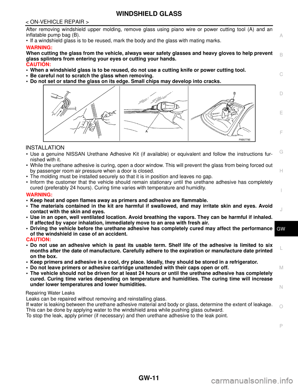
After removing windshield upper molding, remove glass using piano wire or power cutting tool (A) and an
inflatable pump bag (B).
If a windshield glass is to be reused, mark the body and the glass with mating marks.
WARNING:
When cutting the glass from the vehicle, always wear safety glasses and heavy gloves to help prevent
glass splinters from entering your eyes or cutting your hands.
CAUTION:
When a windshield glass is to be reused, do not use a cutting knife or power cutting tool.
Be careful not to scratch the glass when removing.
Do not set or stand the glass on its edge. Small chips may develop into cracks.
INSTALLATION
Use a genuine NISSAN Urethane Adhesive Kit (if available) or equivalent and follow the instructions fur-
nished with it.
While the urethane adhesive is curing, open a door window. This will prevent the glass from being forced out
by passenger room air pressure when a door is closed.
The molding must be installed securely so that it is in position and leaves no gap.
Inform the customer that the vehicle should remain stationary until the urethane adhesive has completely
cured (preferably 24 hours). Curing time varies with temperature and humidity.
WARNING:
Keep heat and open flames away as primers and adhesive are flammable.
The materials contained in the kit are harmful if swallowed, and may irritate skin and eyes. Avoid
contact with the skin and eyes.
Use in an open, well ventilated location. Avoid breathing the vapors. They can be harmful if inhaled.
If affected by vapor inhalation, immediately move to an area with fresh air.
Driving the vehicle before the urethane adhesive has completely cured may affect the performance
of the windshield in case of an accident.
CAUTION:
Do not use an adhesive which is past its usable term. Shelf life of the adhesive is limited to six
months after the date of manufacture. Carefully adhere to the expiration or manufacture date printed
on the box.
Keep primers and adhesive in a cool, dry place. Ideally, they should be stored in a refrigerator.
Do not leave primers or adhesive cartridge unattended with their caps open or off.
The vehicle should not be driven for at least 24 hours or until the urethane adhesive has completely
cured. Curing time varies depending on temperature and humidities. The curing time will increase
under lower temperatures and lower humidities.
Repairing Water Leaks
Leaks can be repaired without removing and reinstalling glass.
If water is leaking between the urethane adhesive material and body or glass, determine the extent of leakage.
This can be done by applying water to the windshield area while pushing glass outward.
To stop the leak, apply primer (if necessary) and then urethane adhesive to the leak point.
PIIB5779E
Page 4237 of 5883
![NISSAN TIIDA 2007 Service Workshop Manual LU-30
< ON-VEHICLE REPAIR >[K9K]
OIL COOLER
OIL COOLER
Exploded ViewINFOID:0000000001381543
Removal and InstallationINFOID:0000000001381544
CAUTION:
Be careful not to get burned when the engine and](/img/5/57395/w960_57395-4236.png "NISSAN TIIDA 2007 Service Workshop Manual LU-30
< ON-VEHICLE REPAIR >[K9K]
OIL COOLER
OIL COOLER
Exploded ViewINFOID:0000000001381543
Removal and InstallationINFOID:0000000001381544
CAUTION:
Be careful not to get burned when the engine and")
LU-30
< ON-VEHICLE REPAIR >[K9K]
OIL COOLER
OIL COOLER
Exploded ViewINFOID:0000000001381543
Removal and InstallationINFOID:0000000001381544
CAUTION:
Be careful not to get burned when the engine and engine oil are hot.
When removing, prepare a shop cloth to absorb any oil leakage or spillage.
Completely wipe off any oil that adhere to the engine and the vehicle.
REMOVAL
1. Remove engine undercover using power tool.
2. Drain engine coolant. Refer to CO-58, "
Draining".
CAUTION:
Perform when engine is cold.
3. Remove RH front wheel. Refer to WT-6, "
Rotation".
4. Remove RH fender protector. Refer to EXT-22, "
Removal and Installation".
5. Remove drive belt. Refer to EM-263, "
Removal and Installation".
6. Remove generator and position aside. Refer to CHG-43, "
Removal and Installation".
7. Remove A/C compressor and position aside. Refer to HA-35, "
Removal and Installation of Compressor -
K9K".
8. Remove oil filter and oil filter bracket. Refer to LU-28, "
Replacement".
1. Cylinder block 2. Water pipe 3. O-ring
4. O-ring 5. O-ring 6. Oil cooler
7. Connecting stud 8. O-ring 9. Oil filter bracket
10. Oil pressure switch 11. Oil filter 12. O-ring
13. Connecting bolt
A. To radiator lower hose B. To water pump
E1BIA0011GB
Page 4262 of 5883
MA-22
< ON-VEHICLE MAINTENANCE >
ENGINE MAINTENANCE (HR16DE)
ENGINE MAINTENANCE (HR16DE)
DRIVE BELTS
DRIVE BELTS : CheckingINFOID:0000000001730848
Inspection should be done only when engine is cold or over 30
minutes after the engine is stopped.
Visually check belts for wear, damage, and cracks on inside and
edges.
Turn crankshaft pulley two time clockwise, and make sure tension on all pulleys is equal before doing the
test.
When measuring deflection, apply 98 N (10 kg, 22 lb) at the ( ) marked point.
Measure the belt tension and frequency with acoustic tension gauge (commercial service tool) at the ( )
marked point.
CAUTION:
When the tension and frequency are measured, the acoustic tension gauge should be used.
When checking immediately after installation, first adjust it to the specified value. Then, after turning
crankshaft two turns or more, re-adjust to the specified value to avoid variation in deflection
between pulleys.
DRIVE BELTS : Tension AdjustmentINFOID:0000000001730849
CAUTION:
When belt is replaced with new one, adjust belt tension to the value for “New belt”, because new belt
will not fully seat in the pulley groove.
When tension of the belt being used exceeds “Limit”, adjust it to the value for “After adjusted”.
When installing a belt, make sure it is correctly engaged with the pulley groove.
Never allow oil or engine coolant to get on the belt.
Never twist or bend the belt strongly.
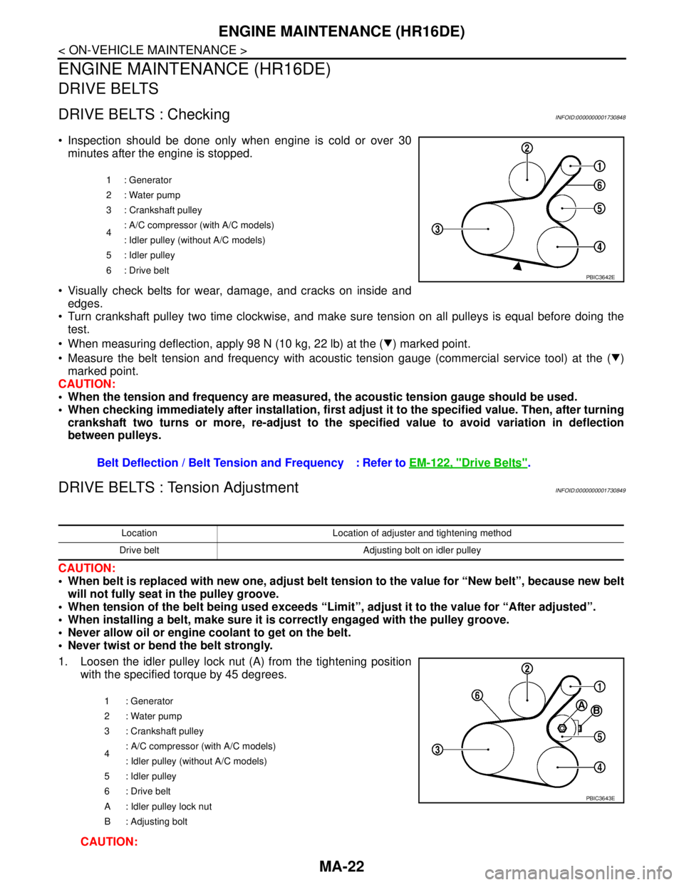
1. Loosen the idler pulley lock nut (A) from the tightening position
with the specified torque by 45 degrees.
CAUTION:
1 : Generator
2: Water pump
3 : Crankshaft pulley
4: A/C compressor (with A/C models)
: Idler pulley (without A/C models)
5 : Idler pulley
6: Drive belt
Belt Deflection / Belt Tension and Frequency : Refer to EM-122, "Drive Belts".
PBIC3642E
Location Location of adjuster and tightening method
Drive belt Adjusting bolt on idler pulley
1 : Generator
2: Water pump
3 : Crankshaft pulley
4: A/C compressor (with A/C models)
: Idler pulley (without A/C models)
5 : Idler pulley
6 : Drive belt
A : Idler pulley lock nut
B : Adjusting bolt
PBIC3643E
Page 4271 of 5883
ENGINE MAINTENANCE (MR18DE)
MA-31
< ON-VEHICLE MAINTENANCE >
C
D
E
F
G
H
I
J
K
L
MB
MAN
OA
ENGINE MAINTENANCE (MR18DE)
DRIVE BELTS
DRIVE BELTS : ComponentINFOID:0000000001730859
DRIVE BELTS : Checking Drive BeltsINFOID:0000000001730860
WARNING:
Be sure to perform this step when the engine is stopped.
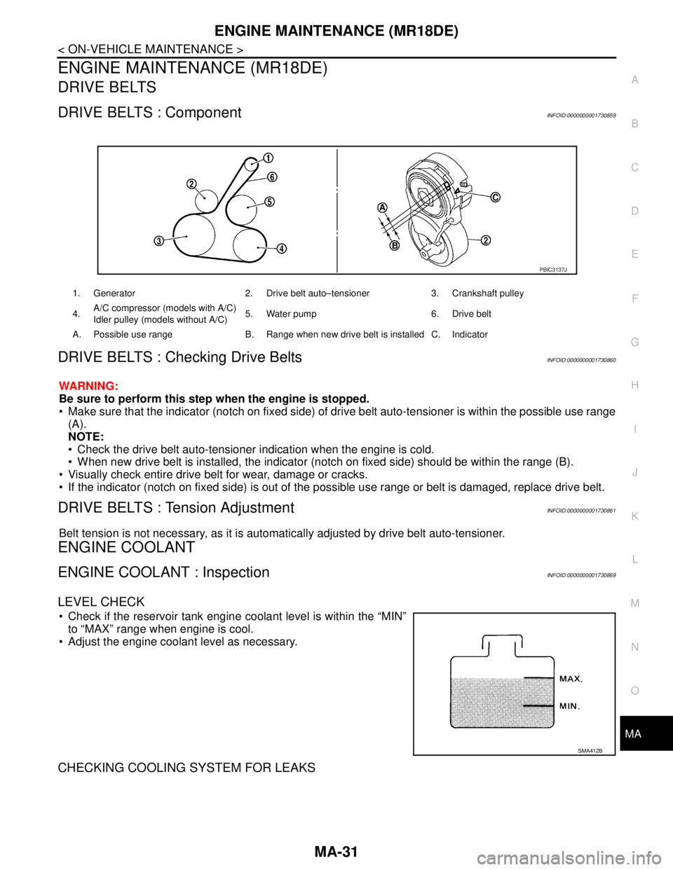
Make sure that the indicator (notch on fixed side) of drive belt auto-tensioner is within the possible use range
(A).
NOTE:
Check the drive belt auto-tensioner indication when the engine is cold.
When new drive belt is installed, the indicator (notch on fixed side) should be within the range (B).
Visually check entire drive belt for wear, damage or cracks.
If the indicator (notch on fixed side) is out of the possible use range or belt is damaged, replace drive belt.
DRIVE BELTS : Tension AdjustmentINFOID:0000000001730861
Belt tension is not necessary, as it is automatically adjusted by drive belt auto-tensioner.
ENGINE COOLANT
ENGINE COOLANT : InspectionINFOID:0000000001730869
LEVEL CHECK
Check if the reservoir tank engine coolant level is within the “MIN”
to “MAX” range when engine is cool.
Adjust the engine coolant level as necessary.
CHECKING COOLING SYSTEM FOR LEAKS
1. Generator 2. Drive belt auto–tensioner 3. Crankshaft pulley
4.A/C compressor (models with A/C)
Idler pulley (models without A/C)5. Water pump 6. Drive belt
A. Possible use range B. Range when new drive belt is installed C. Indicator
PBIC3137J
SMA412B
Page 4284 of 5883
MA-44
< ON-VEHICLE MAINTENANCE >
ENGINE MAINTENANCE (K9K)
4. Start engine without closing reservoir tank cap and keep engine racing at 1,500 rpm for about 2-3 minutes.
If necessary, pour engine coolant up to MAX level.
If coolant overflows reservoir tank hole, install filler cap.
Watch engine coolant temperature gauge so as not overheat the engine.
WARNING:
Be careful not to be scaled with hot engine coolant or vacuum pump when operating.
Radiator fan blade can start at any time and cause personal injuries.
5. Turn off the engine and loosen air relief plug until coolant spills from air relief hole.
6. Close the air relief plug and run the engine at 2,000 rpm until the upper hose becomes hot and radiator
fan operates. Leave the engine running approximately 5 minutes at idle speed and check for sound of
coolant flow while running engine from idle up to 3,000 rpm.
Sound may be noticeable at heater water cock.
7. If sound is heard, bleed air from cooling system by repeating steps 4 to 6 until coolant level no longer
drops.
Check the radiator lower hose for any signs of leakage.
8. Turn off the engine and let it cool down.
Cool down using a fan to reduce the time.
9. After cooling period, loosen the air relief plug and check if coolant spills from the air relief hole. if not,
remove the air relief plug until the coolant spills, and then close the relief air plug. Bleed air from cooling
system by repeating steps 6 to 10 until the coolant spills immediately.
10. Check the engine coolant level when engine is cool and refill to MAX level line if the level is lower.
Clean excess coolant from engine.
11. Check that the reservoir tank cap is tightened.
ENGINE COOLANT : FlushingINFOID:0000000001730883
1. Install reservoir tank if removed.
If water drain plug on cylinder block is removed, close and tighten it. Refer to EM-314, "
Exploded
View".
2. Fill reservoir tank with water until water spills from the air relief hole, then close air relief plug. Reinstall
reservoir tank cap.
3. Run engine and warm it up to normal operating temperature.
4. Rev engine two or three times under no-load.
5. Stop engine and wait until it cools down.
6. Drain water.
7. Repeat steps 1 through 6 until clear water begins to drain from radiator.
8. Blow compressed air into cooling circuit through the reservoir tank valve hole to drain all the water.
RADIATOR
RADIATOR : Checking Radiator CapINFOID:0000000001730884
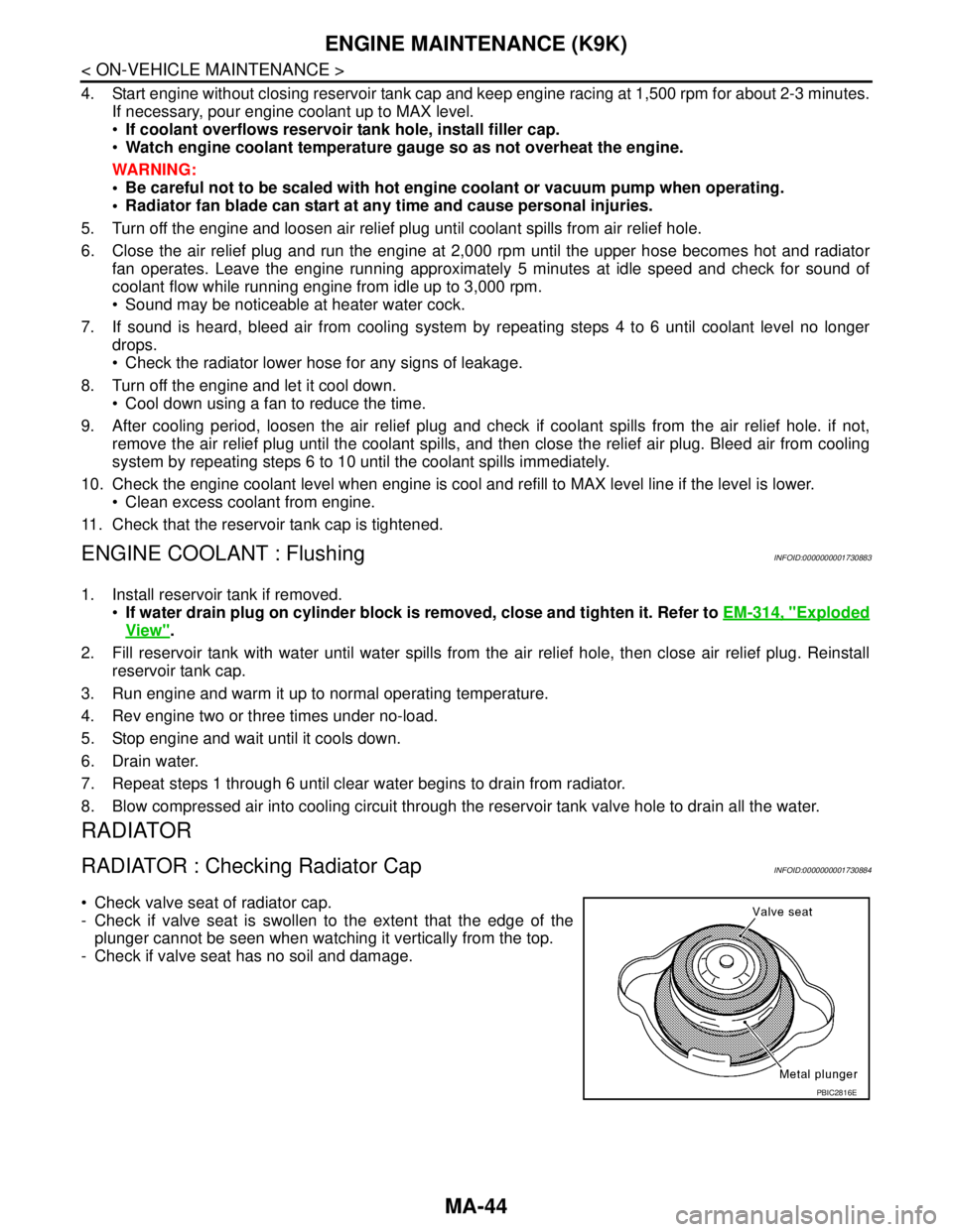
Check valve seat of radiator cap.
- Check if valve seat is swollen to the extent that the edge of the
plunger cannot be seen when watching it vertically from the top.
- Check if valve seat has no soil and damage.
PBIC2816E