door lock NISSAN TIIDA 2007 Service Repair Manual
[x] Cancel search | Manufacturer: NISSAN, Model Year: 2007, Model line: TIIDA, Model: NISSAN TIIDA 2007Pages: 5883, PDF Size: 78.95 MB
Page 5771 of 5883

WCS-56
< ECU DIAGNOSIS >
BCM (BODY CONTROL MODULE)
BCM (BODY CONTROL MODULE)
Reference ValueINFOID:0000000001728312
VALUES ON THE DIAGNOSIS TOOL
Monitor Item Condition Value/Status
AIR COND SWA/C switch OFF OFF
A/C switch ON ON
AUT LIGHT SYSOutside of the room is dark OFF
Outside of the room is bright ON
AUTO LIGHT SWLighting switch OFF OFF
Lighting switch AUTO ON
BACK DOOR SWBack door closed OFF
Back door opened ON
BATTERY VOLT
NOTE:
Diesel engine models
onlyIgnition switch ONApproximately the same as power
supply voltage
CDL LOCK SWDoor lock/unlock switch does not operate OFF
Press door lock/unlock switch to the LOCK side ON
CDL UNLOCK SWDoor lock/unlock switch does not operate OFF
Press door lock/unlock switch to the UNLOCK side ON
DOOR SW-ASPassenger door closed OFF
Passenger door opened ON
DOOR SW-DRDriver door closed OFF
Driver door opened ON
DOOR SW-RLRear LH door closed OFF
Rear LH door opened ON
DOOR SW-RRRear RH door closed OFF
Rear RH door opened ON
ELEC PWR CUT
NOTE:
Diesel engine models
onlyEngine runningFan switch ON (when engine coolant is
cool)
NOTE:
Depending on the ambient tempera-
ture, battery voltage, etc.OFF
The current status maintained with the
signal from ECM received.FREEZ
Fan switch OFF
Fan switch ON after engine warming
UP
NOTE:
Depending on the engine coolant
temperature, ambient temperature,
battery voltage, etc.INHBT
ENG COOLNT T
NOTE:
Diesel engine models
onlyEngine runningApproximately the same as engine
water temperature
ENGINE RPM
NOTE:
Diesel engine models
onlyEngine runningApproximately the same as tachom-
eter reading
Page 5773 of 5883

WCS-58
< ECU DIAGNOSIS >
BCM (BODY CONTROL MODULE)
1: With Intelligent Key
2: With remote keyless entry system
3: HatchbackKEYLESS LOCK
2LOCK button of key fob is not pressed OFF
LOCK button of key fob is pressed ON
KEYLESS UNLOCK
2UNLOCK button of key fob is not pressed OFF
UNLOCK button of key fob is pressed ON
LIT-SEN FAILLight & rain sensor is in normal condition OK
Light & rain sensor is with internal error NOTOK
OIL PRESS SW Ignition switch OFF or ACC
Engine runningOFF
Ignition switch ON ON
OUT SIDE TEMP
NOTE:
Diesel engine modelsIgnition switch ONApproximately the same as outside
air temperature
PASSING SWOther than lighting switch PASS OFF
Lighting switch PASS ON
PUSH SW
1Return to ignition switch to LOCK position OFF
Press ignition switch ON
REAR DEF SWRear window defogger switch OFF OFF
Rear window defogger switch ON ON
RKE LOCK AND
UNLOCK
2NOTE:
The item is indicated, but not monitoredOFF
ON
RR FOG SWRear fog lamp switch OFF OFF
Rear fog lamp switch ON ON
RR WASHER SW
3Rear washer switch OFF OFF
Rear washer switch ON ON
RR WIPER INT
3Rear wiper switch OFF OFF
Rear wiper switch INT ON
RR WIPER ON
3 Rear wiper switch OFF OFF
Rear wiper switch ON ON
RR WIPER STOP
3Rear wiper stop position OFF
Other than rear wiper stop position ON
TAIL LAMP SWLighting switch OFF OFF
Lighting switch 1ST ON
TRNK OPNR SWWhen back door opener switch is not pressed OFF
When back door opener switch is pressed ON
TURN SIGNAL LTurn signal switch OFF OFF
Turn signal switch LH ON
TURN SIGNAL RTurn signal switch OFF OFF
Turn signal switch RH ON
UNLOCK WITH DRNOTE:
The item is indicated, but not monitoredOFF
ON
VEHICLE SPEED While driving Equivalent to speedometer reading Monitor Item Condition Value/Status
Page 5775 of 5883

WCS-60
< ECU DIAGNOSIS >
BCM (BODY CONTROL MODULE)
Check combination switch system terminal waveform under the loaded condition with lighting
switch, turn signal switch and wiper switch OFF is not to be fluctuated by being overloaded.
Turn wiper intermittent dial position to 4 except when checking waveform or voltage of wiper inter-
mittent dial position. Wiper intermittent dial position can be confirmed on CONSULT -III. Refer to
BCS-24, "
COMB SW : CONSULT-III Function (BCM - COMB SW)".
BCM reads the status of the combination switch at 10 ms internal normally. Refer to BCS-7, "
System
Description".
Te r m i n a l N o .
(Wire color)Description
ConditionReference Value
(Approx.)
Signal nameInput/
Output +−
2
(B)Ground Ground — — 0V
3
(G)Ground Key switch OutputInsert mechanical key into ignition key cylin-
derBattery voltage
Remove mechanical key from ignition key
cylinder0V
4
(W)GroundRear window defog-
ger switchOutputRear window
defogger switchNot pressed 5V
While pressing 0V
5
1
(V)GroundBack door opener
switchOutputBack door
opener switchNot pressed Battery voltage
Pressed 0V
5
2
(V)Ground Trunk opener switch OutputTrunk opener
switchNot pressed Battery voltage
Pressed 0V
6
(GR)GroundDoor lock/unlock
switch (Lock) OutputDoor lock/un-
lock switchNot pressed 5V
Pressed to the lock side 0V
Page 5780 of 5883
WCS
BCM (BODY CONTROL MODULE)
WCS-65
< ECU DIAGNOSIS >
C
D
E
F
G
H
I
J
K
L
MB A
O
P
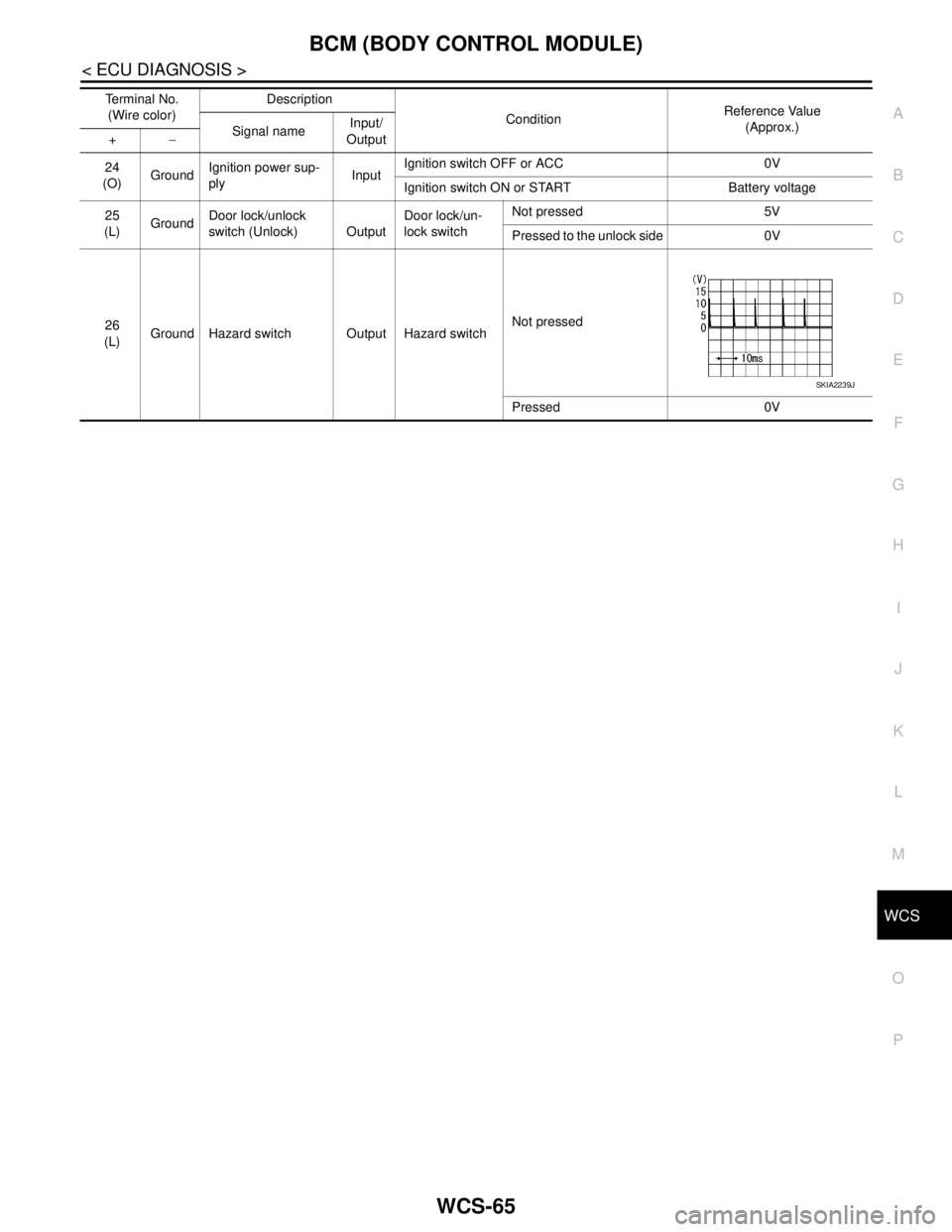
24
(O)GroundIgnition power sup-
plyInputIgnition switch OFF or ACC 0V
Ignition switch ON or START Battery voltage
25
(L)GroundDoor lock/unlock
switch (Unlock) OutputDoor lock/un-
lock switchNot pressed 5V
Pressed to the unlock side 0V
26
(L)Ground Hazard switch Output Hazard switchNot pressed
Pressed 0V Terminal No.
(Wire color)Description
ConditionReference Value
(Approx.)
Signal nameInput/
Output +−
SKIA2239J
Page 5783 of 5883
WCS-68
< ECU DIAGNOSIS >
BCM (BODY CONTROL MODULE)
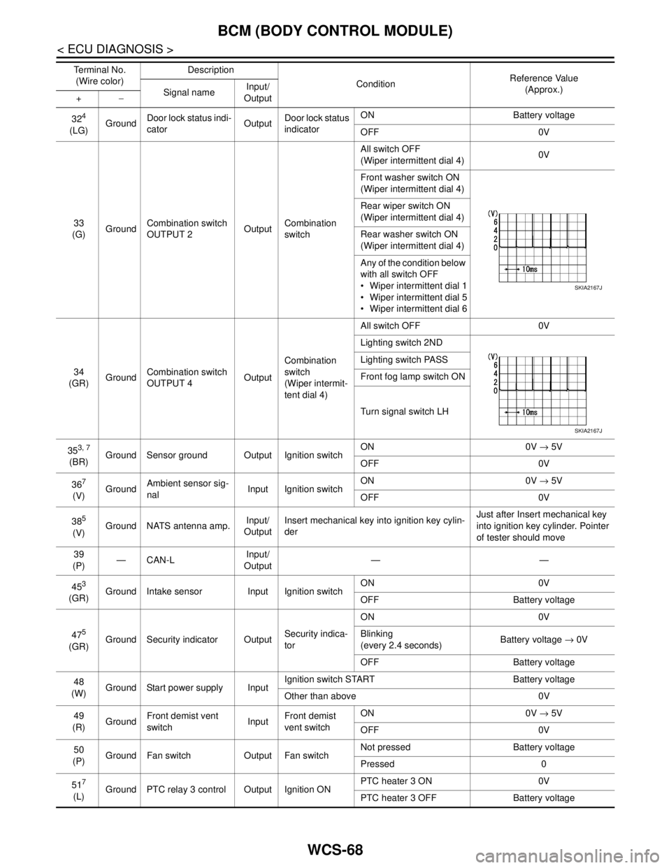
324
(LG)GroundDoor lock status indi-
catorOutputDoor lock status
indicatorON Battery voltage
OFF 0V
33
(G)GroundCombination switch
OUTPUT 2OutputCombination
switchAll switch OFF
(Wiper intermittent dial 4)0V
Front washer switch ON
(Wiper intermittent dial 4)
Rear wiper switch ON
(Wiper intermittent dial 4)
Rear washer switch ON
(Wiper intermittent dial 4)
Any of the condition below
with all switch OFF
Wiper intermittent dial 1
Wiper intermittent dial 5
Wiper intermittent dial 6
34
(GR)GroundCombination switch
OUTPUT 4OutputCombination
switch
(Wiper intermit-
tent dial 4)All switch OFF 0V
Lighting switch 2ND
Lighting switch PASS
Front fog lamp switch ON
Turn signal switch LH
35
3, 7
(BR)Ground Sensor ground Output Ignition switchON 0V → 5V
OFF 0V
36
7
(V)GroundAmbient sensor sig-
nalInput Ignition switchON 0V → 5V
OFF 0V
38
5
(V)Ground NATS antenna amp.Input/
OutputInsert mechanical key into ignition key cylin-
derJust after Insert mechanical key
into ignition key cylinder. Pointer
of tester should move
39
(P)—CAN-LInput/
Output——
45
3
(GR)Ground Intake sensor Input Ignition switchON 0V
OFF Battery voltage
47
5
(GR)Ground Security indicator OutputSecurity indica-
torON 0V
Blinking
(every 2.4 seconds)Battery voltage → 0V
OFF Battery voltage
48
(W)Ground Start power supply InputIgnition switch START Battery voltage
Other than above 0V
49
(R)GroundFront demist vent
switchInputFront demist
vent switchON 0V → 5V
OFF 0V
50
(P)Ground Fan switch Output Fan switchNot pressed Battery voltage
Pressed 0
51
7
(L)Ground PTC relay 3 control Output Ignition ONPTC heater 3 ON 0V
PTC heater 3 OFF Battery voltage Te r m i n a l N o .
(Wire color)Description
ConditionReference Value
(Approx.)
Signal nameInput/
Output +−
SKIA2167J
SKIA2167J
Page 5784 of 5883
WCS
BCM (BODY CONTROL MODULE)
WCS-69
< ECU DIAGNOSIS >
C
D
E
F
G
H
I
J
K
L
MB A
O
P
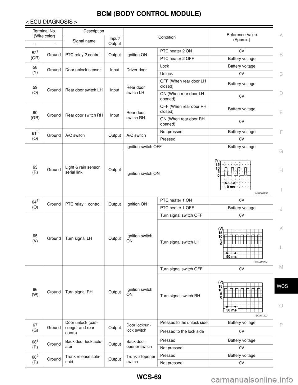
527
(GR)Ground PTC relay 2 control Output Ignition ONPTC heater 2 ON 0V
PTC heater 2 OFF Battery voltage
58
(Y)Ground Door unlock sensor Input Driver doorLock Battery voltage
Unlock 0V
59
(O)Ground Rear door switch LH InputRear door
switch LHOFF (When rear door LH
closed) Battery voltage
ON (When rear door LH
opened)0V
60
(GR)Ground Rear door switch RH InputRear door
switch RHOFF (When rear door RH
closed) Battery voltage
ON (When rear door RH
opened)0V
61
3
(O)Ground A/C switch Output A/C switchNot pressed Battery voltage
Pressed 0V
63
(R)GroundLight & rain sensor
serial linkOutputIgnition switch OFF Battery voltage
Ignition switch ON
64
7
(O)Ground PTC relay 1 control Output Ignition ONPTC heater 1 ON 0V
PTC heater 1 OFF Battery voltage
65
(V)Ground Turn signal LH OutputIgnition switch
ONTurn signal switch OFF 0V
Turn signal switch LH
66
(W)Ground Turn signal RH OutputIgnition switch
ONTurn signal switch OFF 0V
Turn signal switch RH
67
(G)GroundDoor unlock (pas-
senger and rear
doors)OutputDoor lock/un-
lock switchPressed to the unlock side Battery voltage
Pressed to the lock side 0V
68
1
(R)GroundBack door lock actu-
atorOutputBack door
opener switchPressed Battery voltage
Not pressed 0V
68
2
(R)GroundTrunk release sole-
noidOutputTrunk lid opener
switchPressed Battery voltage
Not pressed 0V Terminal No.
(Wire color)Description
ConditionReference Value
(Approx.)
Signal nameInput/
Output +−
MKIB0173E
SKIA1120J
SKIA1120J
Page 5785 of 5883

WCS-70
< ECU DIAGNOSIS >
BCM (BODY CONTROL MODULE)
1: Hatchback
2: Sedan
3: Manual A/C
4: Superlock
5: Remote keyless entry
6: Intelligent Key
7: LHD diesel69
(G)Ground Rear fog lamp OutputLighting switch
1ST and front
fog lamp switch
ONRear fog lamp switch OFF 0V
Rear fog lamp switch ON Battery voltage
70
(B)Ground Ground — — 0V
71
1
(V)Ground Rear wiper motor OutputRear wiper switch OFF 0V
Rear wiper switch ON Battery voltage
72
(LG)GroundBattery power sup-
plyInput — Battery voltage
73
(R)GroundInterior room lamp
power supplyOutputAfter passing the interior room lamp battery
saver operation time0V
Any other time after passing the interior room
lamp battery saver operation timeBattery voltage
74
(Y)GroundBattery power sup-
plyInput — Battery voltage
75
4
(V)Ground Super lock OutputWhen lock button of keyfob or Intelligent Key
is not pressed 0V
When lock button of keyfob or Intelligent Key
is pressed Battery voltage
76
(G)Ground Driver door unlock OutputDoor lock/un-
lock switchPressed to the unlock side Battery voltage
Pressed to the lock side 0V
77
(SB)Ground Door lock (All) OutputDoor lock/un-
lock switchPressed to the unlock side 0V
Pressed to the lock side Battery voltage
78
(L)GroundPower window pow-
er supplyOutput Ignition switchOFF or ACC 0V
ON Battery voltage
79
(Y)GroundBattery power sup-
plyInput — Battery voltage Te r m i n a l N o .
(Wire color)Description
ConditionReference Value
(Approx.)
Signal nameInput/
Output +−
Page 5791 of 5883
WCS-76
< SYMPTOM DIAGNOSIS >
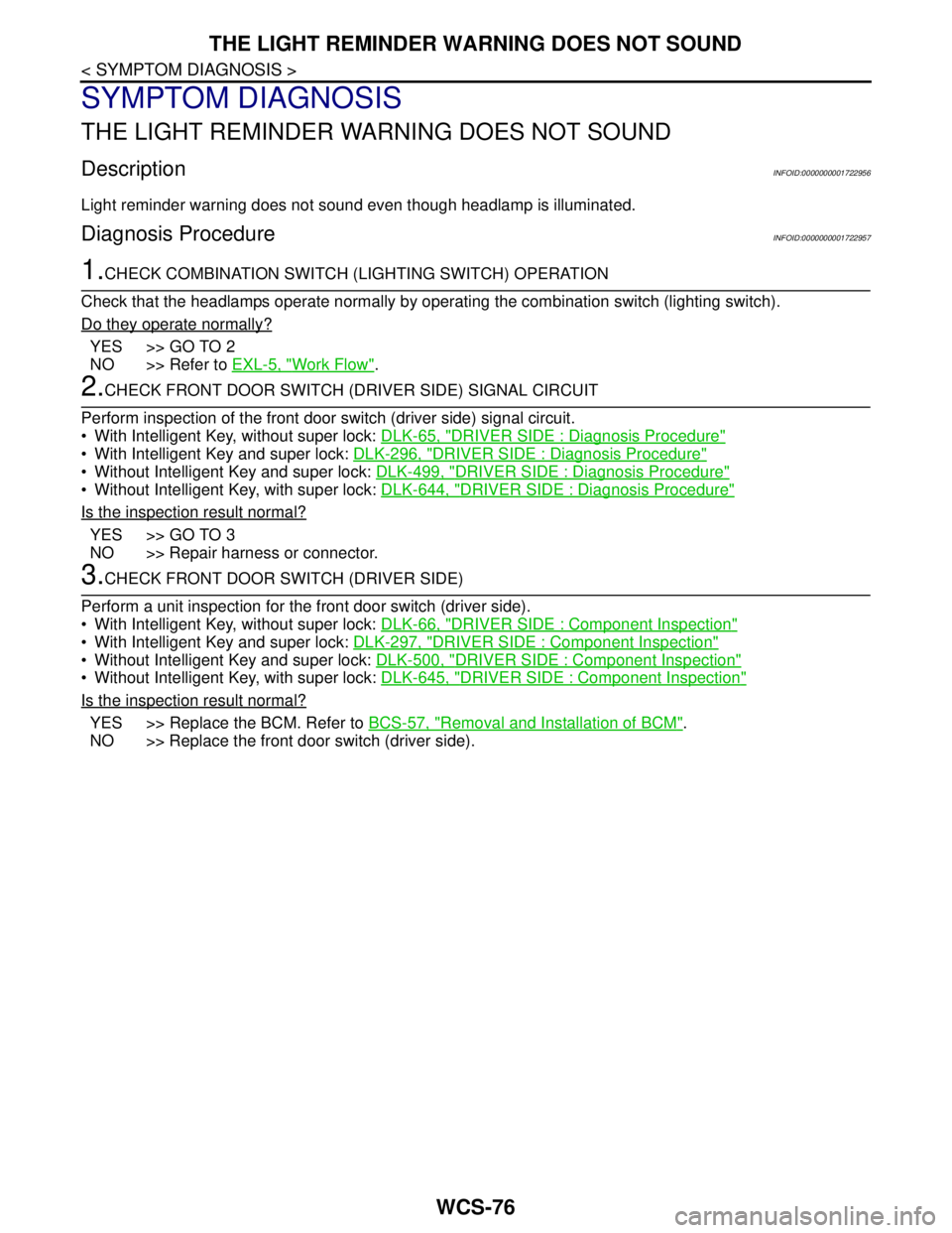
THE LIGHT REMINDER WARNING DOES NOT SOUND
SYMPTOM DIAGNOSIS
THE LIGHT REMINDER WARNING DOES NOT SOUND
DescriptionINFOID:0000000001722956
Light reminder warning does not sound even though headlamp is illuminated.
Diagnosis ProcedureINFOID:0000000001722957
1.CHECK COMBINATION SWITCH (LIGHTING SWITCH) OPERATION
Check that the headlamps operate normally by operating the combination switch (lighting switch).
Do they operate normally?
YES >> GO TO 2
NO >> Refer to EXL-5, "
Work Flow".
2.CHECK FRONT DOOR SWITCH (DRIVER SIDE) SIGNAL CIRCUIT
Perform inspection of the front door switch (driver side) signal circuit.
With Intelligent Key, without super lock: DLK-65, "
DRIVER SIDE : Diagnosis Procedure"
With Intelligent Key and super lock: DLK-296, "DRIVER SIDE : Diagnosis Procedure"
Without Intelligent Key and super lock: DLK-499, "DRIVER SIDE : Diagnosis Procedure"
Without Intelligent Key, with super lock: DLK-644, "DRIVER SIDE : Diagnosis Procedure"
Is the inspection result normal?
YES >> GO TO 3
NO >> Repair harness or connector.
3.CHECK FRONT DOOR SWITCH (DRIVER SIDE)
Perform a unit inspection for the front door switch (driver side).
With Intelligent Key, without super lock: DLK-66, "
DRIVER SIDE : Component Inspection"
With Intelligent Key and super lock: DLK-297, "DRIVER SIDE : Component Inspection"
Without Intelligent Key and super lock: DLK-500, "DRIVER SIDE : Component Inspection"
Without Intelligent Key, with super lock: DLK-645, "DRIVER SIDE : Component Inspection"
Is the inspection result normal?
YES >> Replace the BCM. Refer to BCS-57, "Removal and Installation of BCM".
NO >> Replace the front door switch (driver side).
Page 5793 of 5883

WCS-78
< SYMPTOM DIAGNOSIS >
THE KEY WARNING DOES NOT SOUND
THE KEY WARNING DOES NOT SOUND
DescriptionINFOID:0000000001722960
Key warning does not sound even though key is in ignition and front door (driver side) is opened.
Diagnosis ProcedureINFOID:0000000001722961
1.CHECK WARNING CHIME OPERATION
With key removed from the ignition and the front door (driver side) open, turn the lighting switch to 1st or 2nd
position.
Does warning chime sound?
YES >> GO TO 2
NO >> Replace combination meter. Refer to MWI-94, "
Removal and Installation".
2.CHECK KEY SWITCH CIRCUIT
Perform inspection of the key switch circuit. Refer to WCS-26, "
DiagnosisProcedure" (with Intelligent Key) or
WCS-28, "
DiagnosisProcedure" (without Intelligent Key).
Is the inspection result normal?
YES >> GO TO 3
NO >> Repair harness or connector.
3.CHECK KEY SWITCH
Perform a unit inspection for the key switch. Refer to WCS-27, "
Component Inspection" (with Intelligent Key)
or WCS-29, "
Component Inspection" (without Intelligent Key).
Is the inspection result normal?
YES >> Replace the BCM. Refer to BCS-57, "Removal and Installation of BCM".
NO >> Replace the key switch and ignition knob switch (with Intelligent Key) or key switch and key lock
solenoid (without Intelligent Key).
Page 5816 of 5883

WW-14
< FUNCTION DIAGNOSIS >
DIAGNOSIS SYSTEM (BCM)
DIAGNOSIS SYSTEM (BCM)
COMMON ITEM
COMMON ITEM : CONSULT-III Function (BCM - COMMON ITEM)INFOID:0000000001366604
APPLICATION ITEM
CONSULT-III performs the following functions via CAN communication with BCM.
SYSTEM APPLICATION
BCM can perform the following functions for each system.
NOTE:
It can perform the diagnosis modes except the following for all sub system selection items.
WIPER
WIPER : CONSULT-III Function (BCM - WIPER)INFOID:0000000001366605
WORK SUPPORT
*:Factory setting
DATA MONITOR
Diagnosis mode Function Description
WORK SUPPORT Changes the setting for each system function.
SELF-DIAG RESULTS Displays the diagnosis results judged by BCM. Refer to BCS-54, "
DTCIndex".
CAN DIAG SUPPORT MNTR Monitors the reception status of CAN communication viewed from BCM.
DATA MONITOR The BCM input/output signals are displayed.
ACTIVE TEST The signals used to activate each device are forcibly supplied from BCM.
ECU IDENTIFICATION The BCM part number is displayed.
CONFIGURATION Enables to read and save the vehicle specification.
Enables to write the vehicle specification when replacing BCM.
System Sub system selection itemDiagnosis mode
WORK SUPPORT DATA MONITOR ACTIVE TEST
—BCM×
Exterior lamp HEAD LAMP×××
Wiper and washer WIPER×××
Combination switch COMB SW×
Back door switch DOOR LOCK××
Service itemSetting
itemDescription
WIPER SPEED
SETTINGON*With vehicle speed
(Front wiper intermittent time linked with the vehicle speed and wiper intermittent dial position)
OFFWithout vehicle speed
(Front wiper intermittent time linked with the wiper intermittent dial position)
Monitor Item
[Unit]Description
IGN ON SW Ignition switch ON status judged from ignition power supply.
IGN SW CAN Ignition switch ON status received from IPDM E/R with CAN communication.