ECO NISSAN TIIDA 2007 Service Manual PDF
[x] Cancel search | Manufacturer: NISSAN, Model Year: 2007, Model line: TIIDA, Model: NISSAN TIIDA 2007Pages: 5883, PDF Size: 78.95 MB
Page 223 of 5883

BRAKE MASTER CYLINDER
BR-31
< DISASSEMBLY AND ASSEMBLY >
C
D
E
G
H
I
J
K
L
MA
B
BR
N
O
P
2. Using a pin-punch [commercial service tool: diameter approx. 4
mm (0.16 in)], remove pin from reservoir tank.
3. Remove master cylinder assembly from vise.
4. Remove reservoir tank and grommet from cylinder body.
5. While pushing primary piston, remove piston stopper through
secondary tank boss hole in the cylinder body.
6. Remove snap ring with pushing primary piston.
CAUTION:
Be careful not to pop out piston.
7. Holding rod of primary piston, remove primary piston assembly,
plate and guide assembly by pulling straight to prevent piston
cup from being caught by the inner wall of cylinder.
8. Remove plate and guide assembly from primary piston.
CAUTION:
Be careful not to damage rod from the inner wall of plate.
9. Tap flange using a soft block such as wood, and carefully pull
secondary piston assembly straight out to prevent cylinder inner
wall from being damaged.
INSPECTION AFTER DISASSEMBLY
Cylinder Body
Check the inner wall of cylinder for damage, wear, corrosion, and pin holes. Replace cylinder body if neces-
sary.
ASSEMBLY
CAUTION:
Never use mineral oils such as kerosene or gasoline during the cleaning and assembly processes.
Make sure that there is no foreign material such as dirt and dust on the inner wall of cylinder, piston,
and piston cup. Be careful not to damage parts with a service tool when assembling.
Do not drop parts. If a part is dropped, do not use it.
WFIA0515E
WFIA0516E
BRA0561DWFIA0517E
WFIA0518E
Page 224 of 5883
BR-32
< DISASSEMBLY AND ASSEMBLY >
BRAKE MASTER CYLINDER
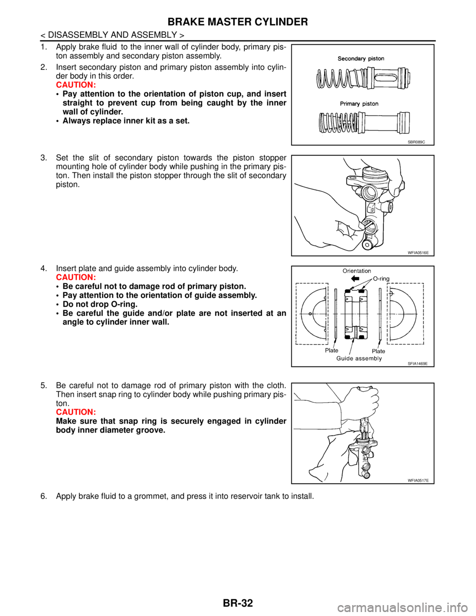
1. Apply brake fluid to the inner wall of cylinder body, primary pis-
ton assembly and secondary piston assembly.
2. Insert secondary piston and primary piston assembly into cylin-
der body in this order.
CAUTION:
Pay attention to the orientation of piston cup, and insert
straight to prevent cup from being caught by the inner
wall of cylinder.
Always replace inner kit as a set.
3. Set the slit of secondary piston towards the piston stopper
mounting hole of cylinder body while pushing in the primary pis-
ton. Then install the piston stopper through the slit of secondary
piston.
4. Insert plate and guide assembly into cylinder body.
CAUTION:
Be careful not to damage rod of primary piston.
Pay attention to the orientation of guide assembly.
Do not drop O-ring.
Be careful the guide and/or plate are not inserted at an
angle to cylinder inner wall.
5. Be careful not to damage rod of primary piston with the cloth.
Then insert snap ring to cylinder body while pushing primary pis-
ton.
CAUTION:
Make sure that snap ring is securely engaged in cylinder
body inner diameter groove.
6. Apply brake fluid to a grommet, and press it into reservoir tank to install.
SBR089C
WFIA0516E
SFIA1469E
WFIA0517E
Page 228 of 5883
BR-36
< DISASSEMBLY AND ASSEMBLY >
FRONT DISC BRAKE
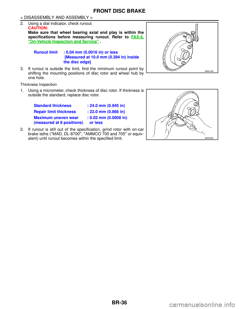
2. Using a dial indicator, check runout.
CAUTION:
Make sure that wheel bearing axial end play is within the
specifications before measuring runout. Refer to FA X - 5 ,
"On-Vehicle Inspection and Service" .
3. If runout is outside the limit, find the minimum runout point by
shifting the mounting positions of disc rotor and wheel hub by
one hole.
Thickness Inspection
1. Using a micrometer, check thickness of disc rotor. If thickness is
outside the standard, replace disc rotor.
2. If runout is still out of the specification, grind rotor with on-car
brake lathe (″MAD, DL-8700″, ″AMMCO 700 and 705″ or equiv-
alent) until runout becomes within the specified limit.Runout limit : 0.04 mm (0.0016 in) or less
[Measured at 10.0 mm (0.394 in) inside
the disc edge]
SBR019B
Standard thickness : 24.0 mm (0.945 in)
Repair limit thickness : 22.0 mm (0.866 in)
Maximum uneven wear
(measured at 8 positions): 0.02 mm (0.0008 in)
or less
SBR020B
Page 232 of 5883
BR-40
< SERVICE DATA AND SPECIFICATIONS (SDS)
SERVICE DATA AND SPECIFICATIONS (SDS)
SERVICE DATA AND SPECIFICATIONS (SDS)
SERVICE DATA AND SPECIFICATIONS (SDS)
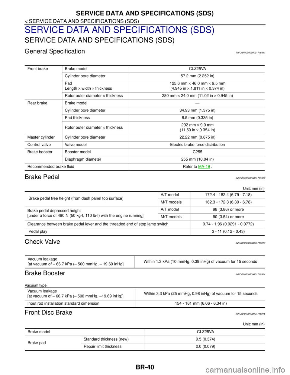
General SpecificationINFOID:0000000001716911
Brake PedalINFOID:0000000001716912
Unit: mm (in)
Check ValveINFOID:0000000001716913
Brake BoosterINFOID:0000000001716914
Vacuum type
Front Disc BrakeINFOID:0000000001716915
Unit: mm (in)
Front brake Brake model CLZ25VA
Cylinder bore diameter 57.2 mm (2.252 in)
Pad
Length × width × thickness125.6 mm × 46.0 mm × 9.5 mm
(4.945 in × 1.811 in × 0.374 in)
Rotor outer diameter × thickness 280 mm × 24.0 mm (11.02 in × 0.945 in)
Rear brake Brake model —
Cylinder bore diameter 34.93 mm (1.375 in)
Pad thickness 8.5 mm (0.335 in)
Rotor outer diameter × thickness292 mm × 9.0 mm
(11.50 in × 0.354 in)
Master cylinder Cylinder bore diameter 22.22 mm (0.875 in)
Control valve Valve model Electric brake force distribution
Brake booster Booster model C255
Diaphragm diameter 255 mm (10.04 in)
Recommended brake fluid Refer to MA-19
.
Brake pedal free height (from dash panel top surface)A/T model 172.4 - 182.4 (6.79 - 7.18)
M/T models 162.3 - 172.3 (6.39 - 6.78)
Brake pedal depressed height
[under a force of 490 N (50 kg-f, 110 lb-f) with the engine running]A/T model 98 (3.86) or more
M/T models 90 (3.54) or more
Clearance between brake pedal lever and the threaded end of stop lamp switch 0.74 - 1.96 (0.0291 - 0.0772)
Pedal play3 - 11 (0.12 - 0.43)
Vacuum leakage
[at vacuum of – 66.7 kPa (– 500 mmHg, – 19.69 inHg]Within 1.3 kPa (10 mmHg, 0.39 inHg) of vacuum for 15 seconds
Vacuum leakage
[at vacuum of – 66.7 kPa (– 500 mmHg, –19.69 inHg)]Within 3.3 kPa (25 mmHg, 0.98 inHg) of vacuum for 15 seconds
Input rod installation standard dimension 154 - 161 mm (6.06 - 6.34 in)
Brake modelCLZ25VA
Brake padStandard thickness (new) 9.5 (0.374)
Repair limit thickness 2.0 (0.079)
Page 244 of 5883

INSPECTION AND ADJUSTMENT
BRC-11
< BASIC INSPECTION >[ABS]
C
D
E
G
H
I
J
K
L
MA
B
BRC
N
O
P
>> GO TO 2
2.PERFORM THE NEUTRAL POSITION ADJUSTMENT FOR THE STEERING ANGLE SENSOR
1. On the CONSULT-III screen, touch “WORK SUPPORT” and “ST ANG SEN ADJUSTMENT” in order.
2. Touch “START”.
CAUTION:
Do not touch steering wheel while adjusting steering angle sensor.
3. After approximately 10 seconds, touch “END”.
NOTE:
After approximately 60 seconds, it ends automatically.
4. Turn ignition switch OFF, then turn it ON again.
CAUTION:
Be sure to perform above operation.
>> GO TO 3
3.CHECK DATA MONITOR
1. Run vehicle with front wheels in straight-ahead position, then stop.
2. Select “DATA MONITOR”. Then make sure “STR ANGLE SIG” is within 0±2.5°.
Is the steering angle within the specified range?
YES >> GO TO 4
NO >> Perform the neutral position adjustment for the steering angle sensor again, GO TO 1
4.ERASE THE SELF-DIAGNOSIS MEMORY
Erase the self-diagnosis memory of the ABS actuator and electric unit (control unit) and ECM.
ABS actuator and electric unit (control unit): Refer to BRC-25, "
CONSULT-III Function (ABS)".
ECM, refer to:
-EC-107, "
CONSULT-III Function" (HR16DE with EURO-OBD)
-EC-462, "
CONSULT-III Function" (HR16DE without EURO-OBD)
-EC-772, "
CONSULT-III Function" (MR18DE)
-EC-1104, "
Diagnosis Description" (K9K)
Are the memories erased?
YES >> INSPECTION END
NO >> Check the items indicated by the self-diagnosis.
CALIBRATION OF DECEL G SENSOR
CALIBRATION OF DECEL G SENSOR : DescriptionINFOID:0000000001731357
Refer to the table below to determine if calibration of the decel G sensor is required.
×: Required –: Not required
Situation Calibration of decel G sensor
Removing/Installing ABS actuator and electric unit (control unit) —
Replacing ABS actuator and electric unit (control unit)×
Removing/Installing steering angle sensor×
Replacing steering angle sensor×
Removing/Installing steering components×
Replacing steering components×
Removing/Installing suspension components×
Replacing suspension components×
Change tires to new ones—
Tire rotation—
Adjusting wheel alignment×
Page 245 of 5883

BRC-12
< BASIC INSPECTION >[ABS]
INSPECTION AND ADJUSTMENT
CALIBRATION OF DECEL G SENSOR : Special Repair Requirement
INFOID:0000000001731358
CALIBRATION OF DECEL G SENSOR
CAUTION:
To calibrate the decel G sensor, make sure to use CONSULT-III
(Calibration cannot be done without CONSULT-III)
1.ALIGN THE VEHICLE STATUS
Stop vehicle with front wheels in straight-ahead position.
>> GO TO 2
2.PERFORM CALIBRATION OF DECEL G SENSOR
1. On the CONSULT-III screen, touch “WORK SUPPORT” and “DECEL G SEN CALIBRATION” in order.
2. Touch “START”.
3. After approximately 10 seconds, touch “END”.
NOTE:
After approximately 60 seconds, it ends automatically.
4. Turn ignition switch OFF, then turn it ON again.
CAUTION:
Be sure to perform above operation.
>> GO TO 3
3.CHECK DATA MONITOR
1. Run vehicle with front wheels in straight-ahead position, then stop.
2. Select “DATA MONITOR”. Then make sure “DECEL G SEN” is within ±.
Is the inspection result normal?
YES >> GO TO 4
NO >> Perform calibration of decel G sensor again, GO TO 1
4.ERASE THE SELF-DIAGNOSIS MEMORY
Erase the self-diagnosis memory of the ABS actuator and electric unit (control unit) and ECM.
ABS actuator and electric unit (control unit): Refer to BRC-25, "
CONSULT-III Function (ABS)".
ECM, refer to:
-EC-107, "
CONSULT-III Function" (HR16DE with EURO-OBD)
-EC-462, "
CONSULT-III Function" (HR16DE without EURO-OBD)
-EC-772, "
CONSULT-III Function" (MR18DE)
-EC-1104, "
Diagnosis Description" (K9K)
Are the memories erased?
YES >> INSPECTION END
NO >> Check the items indicated by the self-diagnosis.
Page 260 of 5883

DIAGNOSIS SYSTEM [ABS ACTUATOR AND ELECTRIC UNIT (CONTROL
UNIT)]
BRC-27
< FUNCTION DIAGNOSIS >[ABS]
C
D
E
G
H
I
J
K
L
MA
B
BRC
N
O
P
CV1
(ON/OFF)––×Front side switch-over solenoid
valve (cut valve) (ON/OFF) status is
displayed.
CV2
(ON/OFF)––×Rear side switch-over solenoid
valve (cut-valve) (ON/OFF) status is
displayed.
SV1
(ON/OFF)––×Front side switch-over solenoid
valve (suction valve) (ON/OFF) sta-
tus is displayed.
SV2
(ON/OFF)––×Rear side switch-over solenoid
valve (suction valve) (ON/OFF) sta-
tus is displayed.
VDC FAIL SIG
(ON/OFF)––×VDC fail signal (ON/OFF) status is
displayed.
TCS FAIL SIG
(ON/OFF)––×TCS fail signal (ON/OFF) status is
displayed.
ABS FAIL SIG
(ON/OFF)––×ABS fail signal (ON/OFF) status is
displayed.
EBD FAIL SIG
(ON/OFF)––×EBD fail signal (ON/OFF) status is
displayed.
FLUID LEV SW
(ON/OFF)×–×Brake fluid level switch (ON/OFF)
status is displayed.
EBD SIGNAL
(ON/OFF)––×EBD operation (ON/OFF) status is
displayed.
ABS SIGNAL
(ON/OFF)––×ABS operation (ON/OFF) status is
displayed.
TCS SIGNAL
(ON/OFF)––×TCS operation (ON/OFF) status is
displayed.
VDC SIGNAL
(ON/OFF)––×VDC operation (ON/OFF) status is
displayed.
EBD WARN LAMP – –×Brake warning lamp (ON/OFF) sta-
tus is displayed.
SLCT LVR POSI×××Shift position judged by PNP switch
signal.
R POSI SIG – –×Shift position judged by PNP switch
signal.
2WD/4WD – –×It recognizes on software whether it
is 2WD and whether it is in 4WD
state.
BST OPER SIG – –×
Active booster operation (ON/OFF)
status is displayed.
PRESS SENSOR×–×Brake pressure detected by pres-
sure sensor is displayed.
CRANKING SIG – –×The input state of the key SW
START position signal is displayed.
PRESS SEN 2 – –×Brake pressure detected by pres-
sure sensor is displayed.
DELTA S SEN – –×The amount of stroke sensor move-
ments in the active booster detected
by DELTA S SEN is displayed. Item
(Unit)Data monitor item selection
Remarks
ECU INPUT
SIGNALSMAIN
SIGNALSSELECTION
FROM MENU
Page 261 of 5883

BRC-28
< FUNCTION DIAGNOSIS >[ABS]
DIAGNOSIS SYSTEM [ABS ACTUATOR AND ELECTRIC UNIT (CONTROL
UNIT)]
×: Applicable
–: Not applicable
ACTIVE TEST MODE
CAUTION:
• Do not perform active test while driving vehicle.
Make sure to completely bleed air from brake system.
The active test cannot be performed with the ABS warning lamp, VDC OFF indicator lamp, SLIP indi-
cator lamp or brake warning lamp on.
ABS warning lamp, VDC OFF indicator lamp, SLIP indicator lamp and brake warning lamp are on
during active test.
NOTE:
When active test is performed while depressing the pedal, the pedal depression amount will change. This is
normal. (Only solenoid valve and ABS motor.)
“TEST IS STOPPED” is displayed 10 seconds after operation start.
After “TEST IS STOPPED” is displayed, to perform test again, touch BACK.
Test Item
SOLENOID VALVE When performing an active test of the ABS function, select the “MAIN SIGNALS” for each test item. In addi-
tion, when performing an active test of the VDC/TCS function, select the item menu for each test item.
For ABS solenoid valve, touch “UP”, “KEEP”, and “DOWN” on the display screen. For ABS solenoid valve
(ACT), touch “UP”, “ACT UP”, “ACT KEEP” and confirm that solenoid valves operate as shown in the table
below.
RELEASE SW NO – –×Release switch signal (ON/OFF)
status is displayed. “ON” indicates
that the brake pedal is depressed.
“OFF”“ is that the brake pedal is re-
leased.
RELEASE SW NC – –×Release switch signal (ON/OFF)
status is displayed. “OFF” indicates
that the brake pedal is depressed
on. “ON” is that the brake pedal is
released.
OHB FAIL – –×OHB fail status is displayed.
HBA FAIL – –×HBA fail status is displayed.
OHB SIG – –×OHB operation (ON/OFF) status is
displayed.
HBA SIG – –×HBA operation (ON/OFF) status is
displayed.
PRES CTRL ACC – –×This item is not used for this model.
PRES FAIL ACC – –×This item is not used for this model.
STP OFF RLY – –×Stop lamp relay signal (ON/OFF)
status is displayed. Item
(Unit)Data monitor item selection
Remarks
ECU INPUT
SIGNALSMAIN
SIGNALSSELECTION
FROM MENU
OperationABS solenoid valve ABS solenoid valve (ACT)
UP KEEP DOWN UPACTUA-
TOR UPACTUA-
TOR KEEP
FR RH SOL
FR RH ABS SOLE-
NOID (ACT)FR RH IN SOL OFF ON ON OFF OFF OFF
FR RH OUT SOL OFF OFF ON* OFF OFF OFF
FR LH SOL
FR LH ABS SOLE-
NOID (ACT)FR LH IN SOL OFF ON ON OFF OFF OFF
FR LH OUT SOL OFF OFF ON* OFF OFF OFF
Page 262 of 5883

DIAGNOSIS SYSTEM [ABS ACTUATOR AND ELECTRIC UNIT (CONTROL
UNIT)]
BRC-29
< FUNCTION DIAGNOSIS >[ABS]
C
D
E
G
H
I
J
K
L
MA
B
BRC
N
O
P
*: ON for 1 to 2 seconds after the touch, and then OFF
ABS MOTOR Touch “ON” and “OFF” on screen. Make sure motor relay and actuator relay operates as shown in table
below.
BOOSTER DRIVE
Touch “UP” and “DOWN” on the screen. Check that booster drive operates as shown in table below.
CAUTION:
Perform active test subject to the conditions below.
Do not operate brake pedal during active test.
Make sure the engine revolution is over 500 rpm.
Make sure the vehicle is not moving.
RR RH SOL
RR RH ABS SOLE-
NOID (ACT)RR RH IN SOL OFF ON ON OFF OFF OFF
RR RH OUT SOL OFF OFF ON* OFF OFF OFF
RR LH SOL
RR LH ABS SOLE-
NOID (ACT)RR LH IN SOL OFF ON ON OFF OFF OFF
RR LH OUT SOL OFF OFF ON* OFF OFF OFF
REAR SOLRR RH IN SOL OFF ON ON OFF OFF OFF
RR RH OUT SOL OFF OFF ON* OFF OFF OFF
RR LH IN SOL OFF ON ON OFF OFF OFF
RR LH OUT SOL OFF OFF ON* OFF OFF OFF
Operation ON OFF
MOTOR RELAY ON OFF
ACTUATOR RLY ON ON
Operation UP DOWN
STOP LAMP SW ON OFF
BST OPER SIG ON OFF
PRESS SENSOR 50 ± 5 bar 0 bar
PRESS SEN 2 50 ± 5 bar 0 bar
STP OFF RLY OFF OFFOperationABS solenoid valve ABS solenoid valve (ACT)
UP KEEP DOWN UPACTUA-
TOR UPACTUA-
TOR KEEP
Page 266 of 5883

C1105, C1106, C1107, C1108 WHEEL SENSOR-2
BRC-33
< COMPONENT DIAGNOSIS >[ABS]
C
D
E
G
H
I
J
K
L
MA
B
BRC
N
O
P
C1105, C1106, C1107, C1108 WHEEL SENSOR-2
DescriptionINFOID:0000000001731230
When the sensor rotor rotates, the magnetic field changes. It converts the magnetic field changes to current
signals (rectangular wave) and transmits them to the ABS actuator and electric unit (control unit).
DTC LogicINFOID:0000000001731231
DTC DETECTION LOGIC
DTC CONFIRMATION PROCEDURE
1.CHECK SELF-DIAGNOSIS RESULTS
Check the self-diagnosis results.
Is above displayed on the self-diagnosis display?
YES >> Proceed to diagnosis procedure. Refer to BRC-33, "Diagnosis Procedure".
NO >> INSPECTION END
Diagnosis ProcedureINFOID:0000000001731232
CAUTION:
Do not check between wheel sensor terminals.
INSPECTION PROCEDURE
1.CONNECTOR INSPECTION
Disconnect the ABS actuator and electric unit (control unit) connector E125 and wheel sensor of malfunction-
ing code.
Check the terminals for deformation, disconnection, looseness or damage.
Is the inspection result normal?
YES >> GO TO 2
NO >> Repair or replace as necessary.
DTC Display item Malfunction detected condition Possible cause
C1105 RR RH SENSOR-2When the circuit in the rear RH wheel sensor is short-cir-
cuited. Or when the distance between the wheel sensor
and sensor rotor is too large and the sensor pulse cannot
be recognized by the control unit.
Harness or connector
Wheel sensor
ABS actuator and electric unit
(control unit) C1106 RR LH SENSOR-2When the circuit in the rear LH wheel sensor is short-cir-
cuited. Or when the distance between the wheel sensor
and sensor rotor is too large and the sensor pulse cannot
be recognized by the control unit.
C1107 FR RH SENSOR-2When the circuit in the front RH wheel sensor is short-cir-
cuited. Or when the distance between the wheel sensor
and sensor rotor is too large and the sensor pulse cannot
be recognized by the control unit.
C1108 FR LH SENSOR-2When the circuit in the front LH wheel sensor is short-cir-
cuited. Or when the distance between the wheel sensor
and sensor rotor is too large and the sensor pulse cannot
be recognized by the control unit.
Self-diagnosis results
RR RH SENSOR-2
RR LH SENSOR-2
FR RH SENSOR-2
FR LH SENSOR-2