back up lamp NISSAN TIIDA 2007 Service Repair Manual
[x] Cancel search | Manufacturer: NISSAN, Model Year: 2007, Model line: TIIDA, Model: NISSAN TIIDA 2007Pages: 5883, PDF Size: 78.95 MB
Page 150 of 5883
BCS
POWER CONSUMPTION CONTROL SYSTEM
BCS-15
< FUNCTION DIAGNOSIS >
C
D
E
F
G
H
I
J
K
L B A
O
P N
Sleep condition
Wake-up operation
BCM transmits sleep wake up signal (wake up) to each unit when any condition listed below is established,
and then goes into normal mode from low power consumption mode.
Each unit starts transmissions with CAN communication by receiving sleep wake up signals. Each unit trans-
mits wake up signals to BCM with CAN communication to convey the start of CAN communication.
Wake-up condition
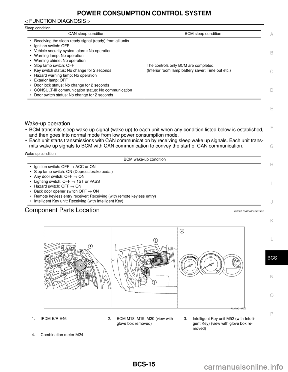
Component Parts LocationINFOID:0000000001451462
CAN sleep condition BCM sleep condition
Receiving the sleep-ready signal (ready) from all units
Ignition switch: OFF
Vehicle security system alarm: No operation
Warning lamp: No operation
Warning chime: No operation
Stop lamp switch: OFF
Key switch status: No change for 2 seconds
Hazard warning lamp: No operation
Exterior lamp: OFF
Door lock status: No change for 2 seconds
CONSULT-III communication status: No communication
Door switch status: No change for 2 secondsThe controls only BCM are completed.
(Interior room lamp battery saver: Time out etc.)
BCM wake-up condition
Ignition switch: OFF → ACC or ON
Stop lamp switch: ON (Depress brake pedal)
Any door switch: OFF → ON
Lighting switch: OFF → 1ST or PASS
Hazard switch: OFF → ON
Back door opener switch OFF → ON
Remote keyless entry receiver: Receiving (with remote keyless entry)
Intelligent Key unit: Receiving (with Intelligent Key)
1. IPDM E/R E46 2. BCM M18, M19, M20 (view with
glove box removed)3. Intelligent Key unit M52 (with Intelli-
gent Key) (view with glove box re-
moved)
4. Combination meter M24
ALMIA0187ZZ
Page 151 of 5883

BCS-16
< FUNCTION DIAGNOSIS >
DIAGNOSIS SYSTEM (BCM)
DIAGNOSIS SYSTEM (BCM)
COMMON ITEM
COMMON ITEM : CONSULT-III Function (BCM - COMMON ITEM)INFOID:0000000001451463
APPLICATION ITEM
CONSULT-III performs the following functions via CAN communication with BCM.
SYSTEM APPLICATION
BCM can perform the following functions for each system.
NOTE:
It can perform the diagnosis modes except the following for all sub system selection items.
1: With remote keyless entry system
2: With Intelligent Key
BCM
Diagnosis mode Function Description
WORK SUPPORT Changes the setting for each system function.
SELF-DIAG RESULTS Displays the diagnosis results judged by BCM. Refer to BCS-54, "
DTCIndex".
CAN DIAG SUPPORT MNTR Monitors the reception status of CAN communication viewed from BCM.
DATA MONITOR The BCM input/output signals are displayed.
ACTIVE TEST The signals used to activate each device are forcibly supplied from BCM.
ECU IDENTIFICATION The BCM part number is displayed.
CONFIGURATION Enables to read and save the vehicle specification.
Enables to write the vehicle specification when replacing BCM.
System Sub system selection itemDiagnosis mode
WORK SUPPORT DATA MONITOR ACTIVE TEST
BCM BCM×
Door lock DOOR LOCK×××
Rear window defogger REAR DEFOGGER××
Warning chime BUZZER××
Interior room lamp timer INT LAMP×××
Remote keyless entry system
1MULTI REMOTE ENT×××
Exterior lamp HEAD LAMP×××
Wiper and washer WIPER×××
Turn signal and hazard warning lamps FLASHER××
Air conditioner AIR CONDITONER×
Intelligent Key system
2INTELLIGENT KEY×
Combination switch COMB SW×
Immobilizer IMMU××
Interior room lamp battery saver BATTERY SAVER×××
Trunk open (sedan)/Back door open
(hatch back)DOOR LOCK××
Vehicle security system THEFT ALM×××
Signal buffer system SIGNAL BUFFER××
PTC heater system PTC HEATER××
Page 154 of 5883

BCS
DIAGNOSIS SYSTEM (BCM)
BCS-19
< FUNCTION DIAGNOSIS >
C
D
E
F
G
H
I
J
K
L B A
O
P N
INT LAMP
INT LAMP : CONSULT-III Function (BCM - INT LAMP)INFOID:0000000001451468
DATA MONITOR
1: With Intelligent Key
2: With remote keyless entry
ACTIVE TEST
MULTIREMOTE ENT
MULTIREMOTE ENT : CONSULT-III Function (BCM - MULTIREMOTE ENT)
INFOID:0000000001451469
WORK SUPPORT
BACK DR OPEN WARN The back door open warning operation can be checked by operating the relevant function (On/Off).
DOOR WARNING IND The door open warning operation can be checked by operating the relevant function (On/Off).Test Item Description
Monitor item
[Unit]Description
IGN ON SW [ON/OFF] Ignition switch (ON) status judges from IGN signal (ignition power supply)
PUSH SW
1 [ON/OFF]Push switch status received from Intelligent Key unit by CAN communication
KEY SW
2 [ON/OFF]The switch status input from key switch
DOOR SW-DR [ON/OFF] The switch status input from front door switch (driver side)
DOOR SW-AS [ON/OFF] The switch status input from front door switch (passenger side)
DOOR SW-RR [ON/OFF] The switch status input from rear door switch RH
DOOR SW- RL [ON/OFF] The switch status input from rear door switch LH
BACK DOOR SW [ON/OFF] The switch status input from back door switch
CDL LOCK SW [ON/OFF] Lock switch status input from door lock and unlock switch
CDL UNLOCK SW [ON/OFF] Unlock switch status input from door lock and unlock switch
KEYLESS LOCK
2 [ON/OFF]Lock signal status received from remote keyless entry receiver (integrated in the
BCM)
KEYLESS UNLOCK
2 [ON/OFF]Unlock signal status received from remote keyless entry receiver (integrated in the
BCM)
I-KEY LOCK
1 [ON/OFF]Lock signal status received from Intelligent Key unit by CAN communication
I-KEY UNLOCK
1 [ON/OFF]Unlock signal status received from Intelligent Key unit by CAN communication
I-KEY ALL UNL
1 [ON/OFF]Unlock signal status received from Intelligent Key unit by CAN communication
Test item Operation Description
INT LAMPONOutputs the interior room lamp control signal to turn the interior room lamps ON.
[Map lamp, personal lamp, room lamp, luggage room lamp (when applicable lamps
switch is in DOOR position.)]
OFF Stops the interior room lamp control signal to turn the interior room lamps.
Page 155 of 5883

BCS-20
< FUNCTION DIAGNOSIS >
DIAGNOSIS SYSTEM (BCM)
DATA MONITOR
ACTIVE TEST
HEADLAMP
HEADLAMP : CONSULT-III Function (BCM - HEAD LAMP)INFOID:0000000001451470
WORK SUPPORT
*: Initial setting
DATA MONITOR
Work Item Description
HAZARD LAMP SETAnswer back function (hazard) mode can be changed in this mode.
For the detail of the setting, refer to DLK-617, "
REMOTE KEYLESS ENTRY : System Descrip-
tion".
AUTO LOCK SETAuto door lock time can be changed in this mode.
MODE 1: 1 minute
MODE 2: 2 minutes
MODE 3: 3 minutes
MODE 4: 4 minutes
MODE 5: 5 minutes
Monitor Item
[Unit}Condition
IGN ON SW [ON/OFF] Indicates condition of ignition switch in ON position.
KEY SW [ON/OFF] Indicates condition of key switch.
KEYLESS LOCK [ON/OFF] Indicates condition of lock signal from keyfob.
KEYLESS UNLOCK [ON/OFF] Indicates condition of unlock signal from keyfob.
DOOR SW-DR [ON/OFF] Indicates condition of front door switch (driver side).
DOOR SW-AS [ON/OFF] Indicates condition of front door switch (passenger side).
DOOR SW-RR [ON/OFF] Indicates condition of rear door switch RH.
DOOR SW-RL [ON/OFF] Indicates condition of rear door switch LH.
BACK DOOR SW [ON/OFF] Indicates condition of back door switch.
CDL LOCK SW [ON/OFF] Indicates condition of door lock and unlock switch.
CDL UNLOCK SW [ON/OFF] Indicates condition of door lock and unlock switch.
RKE LOCK AND UNLOCK This item is indicated, but not monitored.
Test Item Description
DOOR LOCKThis test is able to check warning chime in combination meter operation. [ALL LOCK/ALL UN-
LOCK/DR UNLOCK/OTHER UNLOCK]
INT LAMP This test is able to check interior lamp operation [ON/OFF].
FLASHER This test is able to check flasher operation [LH/RH/OFF].
Work item Setting Description
BATTERY SAVER SETON*
Battery saver mode can be changed.
OFF
Monitor item
[Unit]Description
IGN ON SW [ON/OFF] Ignition switch (ON) status judged from IGN signal (ignition power supply)
Page 159 of 5883

BCS-24
< FUNCTION DIAGNOSIS >
DIAGNOSIS SYSTEM (BCM)
COMB SW
COMB SW : CONSULT-III Function (BCM - COMB SW)INFOID:0000000001451475
DATA MONITOR
IMMU
IMMU : CONSULT-III Function (BCM - IMMU)INFOID:0000000001451476
DATA MONITOR
DOOR SW-RL [ON/OFF] Indicates condition of front door switch LH.
BACK DOOR SW [ON/OFF] Indicates condition of back door switch.Monitor Item
[Unit]Condition
Monitor Item
[Unit]Description
TURN SIGNAL R
[OFF/ON]Displays the status of the TURN RH switch in combination switch judged by BCM with the combination switch
reading function.
TURN SIGNAL L
[OFF/ON]Displays the status of the TURN LH switch in combination switch judged by BCM with the combination switch
reading function.
HI BEAM SW
[OFF/ON]Displays the status of the HI BEAM switch in combination switch judged by BCM with the combination switch
reading function.
H/L SW POS
[OFF/ON]Displays the status of the HEADLAMP switch in combination switch judged by BCM with the combination
switch reading function.
LIGHT SW 1ST
[OFF/ON]Displays the status of the HEADLAMP switch in combination switch judged by BCM with the combination
switch reading function.
PASSING SW
[OFF/ON]Displays the status of the PASSING switch in combination switch judged by BCM with the combination switch
reading function.
AUTO LIGHT SW
[OFF/ON]Displays the status of the AUTO LIGHT switch in combination switch judged by BCM with the combination
switch reading function.
FR FOG SW
[OFF/ON]Displays the status of the FR FOG switch in combination switch judged by BCM with the combination switch
reading function.
RR FOG SW
[OFF/ON]Displays the status of the RR FOG switch in combination switch judged by BCM with the combination switch
reading function.
FR WIPER HI
[OFF/ON]Displays the status of the FR WIPER HI switch in combination switch judged by BCM with the combination
switch reading function.
FR WIPER LOW
[OFF/ON]Displays the status of the FR WIPER LOW switch in combination switch judged by BCM with the combination
switch reading function.
FR WIPER INT
[OFF/ON]Displays the status of the FR WIPER INT switch in combination switch judged by BCM with the combination
switch reading function.
FR WASHER SW
[OFF/ON]Displays the status of the FR WASHER switch in combination switch judged by BCM with the combination
switch reading function.
INT VOLUME
[1 - 7]Displays the status of wiper intermittent dial position judged by BCM with the combination switch reading
function.
RR WIPER ON
[OFF/ON]Displays the status of the RR WIPER switch in combination switch judged by BCM with the combination
switch reading function.
RR WIPER INT
[OFF/ON]Displays the status of the RR WIPER INT switch in combination switch judged by BCM with the combination
switch reading function.
RR WASHER SW
[OFF/ON]Displays the status of the RR WASHER switch in combination switch judged by BCM with the combination
switch reading function.
Page 160 of 5883

BCS
DIAGNOSIS SYSTEM (BCM)
BCS-25
< FUNCTION DIAGNOSIS >
C
D
E
F
G
H
I
J
K
L B A
O
P N
1: With remote keyless entry.
2: With Intelligent Key.
ACTIVE TEST
BATTERY SAVER
BATTERY SAVER : CONSULT-III Function (BCM - BATTERY SAVER)INFOID:0000000001451477
WORK SUPPORT
*: Initial setting
DATA MONITOR
1: With remote keyless entry
2: With Intelligent Key
ACTIVE TEST
Monitor Item Description
IGN ON SW [ON/OFF] Indicates condition of ignition switch in ON position.
KEY SW
1 [ON/OFF]Indicates condition of key switch.
PUSH SW
2 [ON/OFF]Indicates condition of ignition knob switch.
Test Item Description
THEFT IND This test is able to check security indicator operation [ON/OFF].
Work Item Setting Item Setting
ROOM LAMP TIMER SETMODE 1* 15 min.
Sets the interior room lamp battery saver timer operating
time.
MODE 2 30 min.
Monitor Item
[Unit]Description
IGN ON SW [ON/OFF] Ignition switch (ON) status judges from IGN signal (ignition power supply)
KEY SW
1 [ON/OFF]The switch status input from key switch
PUSH SW
2 [ON/OFF]Push switch status received from Intelligent Key unit by CAN communication
DOOR SW-DR [ON/OFF] The switch status input from front door switch (driver side)
DOOR SW-AS [ON/OFF] The switch status input from front door switch (passenger side)
DOOR SW-RR [ON/OFF] The switch status input from rear door switch RH
DOOR SW- RL [ON/OFF] The switch status input from rear door switch LH
BACK DOOR SW [ON/OFF] The switch status input from back door switch
CDL LOCK SW [ON/OFF] Lock switch status input from door lock and unlock switch
CDL UNLOCK SW [ON/OFF] Unlock switch status input from door lock and unlock switch
I-KEY LOCK
2 [ON/OFF]Lock signal status received from Intelligent Key unit by CAN communication
I-KEY UNLOCK
2 [ON/OFF]Unlock signal status received from Intelligent Key unit by CAN communication
KEYLESS LOCK
1 [ON/OFF]Lock signal status received from remote keyless entry receiver (integrated in the
BCM)
KEYLESS UNLOCK
1 [ON/OFF]Unlock signal status received from remote keyless entry receiver (integrated in the
BCM)
Test item Operation Description
BATTERY SAVEROFF Cuts the interior room lamp power supply to turn interior room lamps OFF.
ON Outputs the interior room lamp power supply to turn interior room lamps ON.*
Page 172 of 5883

BCS
BCM (BODY CONTROL MODULE)
BCS-37
< ECU DIAGNOSIS >
C
D
E
F
G
H
I
J
K
L B A
O
P N
I-KEY UNLOCK1UNLOCK button of Intelligent Key is not pressed OFF
UNLOCK button of Intelligent Key is pressed ON
KEY SW
2Mechanical key is removed from key cylinder OFF
Mechanical key is inserted to key cylinder ON
KEYLESS LOCK
2LOCK button of key fob is not pressed OFF
LOCK button of key fob is pressed ON
KEYLESS UNLOCK
2UNLOCK button of key fob is not pressed OFF
UNLOCK button of key fob is pressed ON
LIT-SEN FAILLight & rain sensor is in normal condition OK
Light & rain sensor is with internal error NOTOK
OIL PRESS SW Ignition switch OFF or ACC
Engine runningOFF
Ignition switch ON ON
OUT SIDE TEMP
NOTE:
Diesel engine modelsIgnition switch ONApproximately the same as outside
air temperature
PASSING SWOther than lighting switch PASS OFF
Lighting switch PASS ON
PUSH SW
1Return to ignition switch to LOCK position OFF
Press ignition switch ON
REAR DEF SWRear window defogger switch OFF OFF
Rear window defogger switch ON ON
RKE LOCK AND
UNLOCK
2NOTE:
The item is indicated, but not monitoredOFF
ON
RR FOG SWRear fog lamp switch OFF OFF
Rear fog lamp switch ON ON
RR WASHER SW
3Rear washer switch OFF OFF
Rear washer switch ON ON
RR WIPER INT
3Rear wiper switch OFF OFF
Rear wiper switch INT ON
RR WIPER ON
3 Rear wiper switch OFF OFF
Rear wiper switch ON ON
RR WIPER STOP
3Rear wiper stop position OFF
Other than rear wiper stop position ON
TAIL LAMP SWLighting switch OFF OFF
Lighting switch 1ST ON
TRNK OPNR SWWhen back door opener switch is not pressed OFF
When back door opener switch is pressed ON
TURN SIGNAL LTurn signal switch OFF OFF
Turn signal switch LH ON
TURN SIGNAL RTurn signal switch OFF OFF
Turn signal switch RH ON
UNLOCK WITH DRNOTE:
The item is indicated, but not monitoredOFF
ON
VEHICLE SPEED While driving Equivalent to speedometer reading Monitor Item Condition Value/Status
Page 178 of 5883
BCS
BCM (BODY CONTROL MODULE)
BCS-43
< ECU DIAGNOSIS >
C
D
E
F
G
H
I
J
K
L B A
O
P N
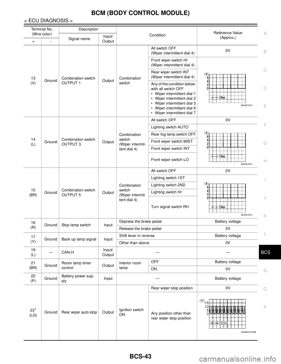
13
(V)GroundCombination switch
OUTPUT 1OutputCombination
switchAll switch OFF
(Wiper intermittent dial 4)0V
Front wiper switch HI
(Wiper intermittent dial 4)
Rear wiper switch INT
(Wiper intermittent dial 4)
Any of the condition below
with all switch OFF
Wiper intermittent dial 1
Wiper intermittent dial 2
Wiper intermittent dial 3
Wiper intermittent dial 6
Wiper intermittent dial 7
14
(L)GroundCombination switch
OUTPUT 3OutputCombination
switch
(Wiper intermit-
tent dial 4)All switch OFF 0V
Lighting switch AUTO
Rear fog lamp switch OFF
Front wiper switch MIST
Front wiper switch INT
Front wiper switch LO
15
(BR)GroundCombination switch
OUTPUT 5OutputCombination
switch
(Wiper intermit-
tent dial 4)All switch OFF 0V
Lighting switch 1ST
Lighting switch 2ND
Lighting switch HI
Turn signal switch RH
16
(R)Ground Stop lamp switch InputDepress the brake pedal Battery voltage
Release the brake pedal 0V
17
(Y)Ground Back up lamp signal InputShift lever in reverse Battery voltage
Other than above 0V
19
(L)—CAN-HInput/
Output——
21
(BR)GroundRoom lamp timer
controlOutputInterior room
lampOFF Battery voltage
ON 0V
22
(P)GroundBattery power sup-
plyInput — Battery voltage
23
1
(LG)Ground Rear wiper auto stop OutputIgnition switch
ONRear wiper stop position 0V
Any position other than
rear wiper stop position Terminal No.
(Wire color)Description
ConditionReference Value
(Approx.)
Signal nameInput/
Output +−
SKIA2167J
SKIA2167J
SKIA2167J
JPMIA0197GB
Page 184 of 5883

BCS
BCM (BODY CONTROL MODULE)
BCS-49
< ECU DIAGNOSIS >
C
D
E
F
G
H
I
J
K
L B A
O
P N
1: Hatchback
2: Sedan
3: Manual A/C
4: Superlock
5: Remote keyless entry
6: Intelligent Key
7: LHD diesel69
(G)Ground Rear fog lamp OutputLighting switch
1ST and front
fog lamp switch
ONRear fog lamp switch OFF 0V
Rear fog lamp switch ON Battery voltage
70
(B)Ground Ground — — 0V
71
1
(V)Ground Rear wiper motor OutputRear wiper switch OFF 0V
Rear wiper switch ON Battery voltage
72
(LG)GroundBattery power sup-
plyInput — Battery voltage
73
(R)GroundInterior room lamp
power supplyOutputAfter passing the interior room lamp battery
saver operation time0V
Any other time after passing the interior room
lamp battery saver operation timeBattery voltage
74
(Y)GroundBattery power sup-
plyInput — Battery voltage
75
4
(V)Ground Super lock OutputWhen lock button of keyfob or Intelligent Key
is not pressed 0V
When lock button of keyfob or Intelligent Key
is pressed Battery voltage
76
(G)Ground Driver door unlock OutputDoor lock/un-
lock switchPressed to the unlock side Battery voltage
Pressed to the lock side 0V
77
(SB)Ground Door lock (All) OutputDoor lock/un-
lock switchPressed to the unlock side 0V
Pressed to the lock side Battery voltage
78
(L)GroundPower window pow-
er supplyOutput Ignition switchOFF or ACC 0V
ON Battery voltage
79
(Y)GroundBattery power sup-
plyInput — Battery voltage Terminal No.
(Wire color)Description
ConditionReference Value
(Approx.)
Signal nameInput/
Output +−
Page 261 of 5883
![NISSAN TIIDA 2007 Service Repair Manual BRC-28
< FUNCTION DIAGNOSIS >[ABS]
DIAGNOSIS SYSTEM [ABS ACTUATOR AND ELECTRIC UNIT (CONTROL
UNIT)]
×: Applicable
–: Not applicable
ACTIVE TEST MODE
CAUTION:
• Do not perform active test while d](/img/5/57395/w960_57395-260.png "NISSAN TIIDA 2007 Service Repair Manual BRC-28
< FUNCTION DIAGNOSIS >[ABS]
DIAGNOSIS SYSTEM [ABS ACTUATOR AND ELECTRIC UNIT (CONTROL
UNIT)]
×: Applicable
–: Not applicable
ACTIVE TEST MODE
CAUTION:
• Do not perform active test while d")
BRC-28
< FUNCTION DIAGNOSIS >[ABS]
DIAGNOSIS SYSTEM [ABS ACTUATOR AND ELECTRIC UNIT (CONTROL
UNIT)]
×: Applicable
–: Not applicable
ACTIVE TEST MODE
CAUTION:
• Do not perform active test while driving vehicle.
Make sure to completely bleed air from brake system.
The active test cannot be performed with the ABS warning lamp, VDC OFF indicator lamp, SLIP indi-
cator lamp or brake warning lamp on.
ABS warning lamp, VDC OFF indicator lamp, SLIP indicator lamp and brake warning lamp are on
during active test.
NOTE:
When active test is performed while depressing the pedal, the pedal depression amount will change. This is
normal. (Only solenoid valve and ABS motor.)
“TEST IS STOPPED” is displayed 10 seconds after operation start.
After “TEST IS STOPPED” is displayed, to perform test again, touch BACK.
Test Item
SOLENOID VALVE When performing an active test of the ABS function, select the “MAIN SIGNALS” for each test item. In addi-
tion, when performing an active test of the VDC/TCS function, select the item menu for each test item.
For ABS solenoid valve, touch “UP”, “KEEP”, and “DOWN” on the display screen. For ABS solenoid valve
(ACT), touch “UP”, “ACT UP”, “ACT KEEP” and confirm that solenoid valves operate as shown in the table
below.
RELEASE SW NO – –×Release switch signal (ON/OFF)
status is displayed. “ON” indicates
that the brake pedal is depressed.
“OFF”“ is that the brake pedal is re-
leased.
RELEASE SW NC – –×Release switch signal (ON/OFF)
status is displayed. “OFF” indicates
that the brake pedal is depressed
on. “ON” is that the brake pedal is
released.
OHB FAIL – –×OHB fail status is displayed.
HBA FAIL – –×HBA fail status is displayed.
OHB SIG – –×OHB operation (ON/OFF) status is
displayed.
HBA SIG – –×HBA operation (ON/OFF) status is
displayed.
PRES CTRL ACC – –×This item is not used for this model.
PRES FAIL ACC – –×This item is not used for this model.
STP OFF RLY – –×Stop lamp relay signal (ON/OFF)
status is displayed. Item
(Unit)Data monitor item selection
Remarks
ECU INPUT
SIGNALSMAIN
SIGNALSSELECTION
FROM MENU
OperationABS solenoid valve ABS solenoid valve (ACT)
UP KEEP DOWN UPACTUA-
TOR UPACTUA-
TOR KEEP
FR RH SOL
FR RH ABS SOLE-
NOID (ACT)FR RH IN SOL OFF ON ON OFF OFF OFF
FR RH OUT SOL OFF OFF ON* OFF OFF OFF
FR LH SOL
FR LH ABS SOLE-
NOID (ACT)FR LH IN SOL OFF ON ON OFF OFF OFF
FR LH OUT SOL OFF OFF ON* OFF OFF OFF