check engine NISSAN TIIDA 2007 Service Repair Manual
[x] Cancel search | Manufacturer: NISSAN, Model Year: 2007, Model line: TIIDA, Model: NISSAN TIIDA 2007Pages: 5883, PDF Size: 78.95 MB
Page 25 of 5883
![NISSAN TIIDA 2007 Service Repair Manual AV-20
< SYMPTOM DIAGNOSIS >[AUDIO WITHOUT NAVIGATION]
NORMAL OPERATING CONDITION
NORMAL OPERATING CONDITION
DescriptionINFOID:0000000001728625
RELATED TO AUDIO
The majority of the audio malfunctions NISSAN TIIDA 2007 Service Repair Manual AV-20
< SYMPTOM DIAGNOSIS >[AUDIO WITHOUT NAVIGATION]
NORMAL OPERATING CONDITION
NORMAL OPERATING CONDITION
DescriptionINFOID:0000000001728625
RELATED TO AUDIO
The majority of the audio malfunctions](/img/5/57395/w960_57395-24.png)
AV-20
< SYMPTOM DIAGNOSIS >[AUDIO WITHOUT NAVIGATION]
NORMAL OPERATING CONDITION
NORMAL OPERATING CONDITION
DescriptionINFOID:0000000001728625
RELATED TO AUDIO
The majority of the audio malfunctions are the result of outside causes (bad CD, electromagnetic interfer-
ence, etc.). Check the symptoms below to diagnose the malfunction.
The vehicle itself can be a source of noise if noise prevention parts or electrical equipment is malfunctioning.
Check that noise is caused and/or changed by engine speed, ignition switch turned to each position, and
operation of each piece of electrical equipment. Then determine the cause.
NOTE:
CD-R is not guaranteed to play because they can contain compressed audio (MP3, WMA) or could be incor-
rectly mastered by the customer on a computer.
Check that the CDs carry the Compact Disc Logo. If not, the disc is not mastered to the red book Compact
Disc Standard and may not play.
Noise resulting from variations in field strength, such as fading noise and multi-path noise, or external noise from trains and other
sources, is not a malfunction.
NOTE:
Fading noise: This noise occurs because of variations in the field strength in a narrow range due to mountains or buildings blocking
the signal.
Multi-path noise: This noise results from a time difference between the broadcast waves directly from the station arriving at the
antenna and the waves reflected by mountains or buildings.
RELATED TO TELEPHONE
Symptoms Cause and Counter measure
Cannot playCheck that the CD was inserted correctly.
Check that the CD is scratched or dirty.
Check that there is condensation inside the player, and if there is, wait until the condensation is
gone (about 1 hour) before using the player.
The player will play correctly after it returns to the normal temperature if there is a temperature
increase error.
Only the music CD files (CD-DA data) will be played if there is a mixture of music CD files (CD-
DA data) and MP3/WMA files on a CD.
Files with extensions other than “.MP3”, “.WMA”, “.mp3”, or “.wma” cannot be played.
Check that the finalization process, such as session close and disc close, is done for the disc.
Check that the CD is protected by copyright.
Poor sound quality Check that the CD is scratched or dirty.
It takes a relatively long time before
the music starts playing.If there are many folder or file levels on the MP3/WMA CD, or if it is a multisession disc, some
time may be required before the music starts playing.
The songs do not play back in the
desired order.The playback order is the order in which the files were written by the software, so the files might
not play in the desired order.
Symptom Possible cause Possible solution
The system does not recognize the
command.
The system recognizes the com-
mand incorrectly.The interior of the vehicle is too noisy.Close the windows or have other occupants
be quiet.
The volume of the voice is too low. Speak louder.
Pronunciation is unclear. Speak clearly.
Voice recognition mode is not yet ready to speak.Push the release “ ” on the steering
switch, and speak a command after the
tone sounds.
5 seconds or more have passed after pushed and
released “ ” on the steering switch.Make sure to speak a command within
5seconds after push and release “ ” on
the steering switch.
Page 44 of 5883
![NISSAN TIIDA 2007 Service Repair Manual AV
DIAGNOSIS SYSTEM (NAVI CONTROL UNIT)
AV-39
< FUNCTION DIAGNOSIS >[AUDIO WITH NAVIGATION]
C
D
E
F
G
H
I
J
K
L
MB A
O
P
DIAGNOSIS SYSTEM (NAVI CONTROL UNIT)
Diagnosis DescriptionINFOID:00000000017286 NISSAN TIIDA 2007 Service Repair Manual AV
DIAGNOSIS SYSTEM (NAVI CONTROL UNIT)
AV-39
< FUNCTION DIAGNOSIS >[AUDIO WITH NAVIGATION]
C
D
E
F
G
H
I
J
K
L
MB A
O
P
DIAGNOSIS SYSTEM (NAVI CONTROL UNIT)
Diagnosis DescriptionINFOID:00000000017286](/img/5/57395/w960_57395-43.png)
AV
DIAGNOSIS SYSTEM (NAVI CONTROL UNIT)
AV-39
< FUNCTION DIAGNOSIS >[AUDIO WITH NAVIGATION]
C
D
E
F
G
H
I
J
K
L
MB A
O
P
DIAGNOSIS SYSTEM (NAVI CONTROL UNIT)
Diagnosis DescriptionINFOID:0000000001728643
MULTI AV SYSTEM on board diagnosis function
The NAVI control unit diagnosis function starts up with audio switch operation and the NAVI control unit per-
forms a diagnosis for each unit in the system during the on board diagnosis.
Perform a CONSULT-III diagnosis if the on board diagnosis does not start, e.g., the screen does not display
anything, the multifunction switch does not function. etc.
On board diagnosis
Description
The trouble diagnosis function has a self-diagnosis mode for conducting trouble diagnosis automatically and
a confirmation/adjustment mode for operating manually.
The self-diagnosis mode performs diagnoses on the NAVI control unit, connections between system compo-
nents as well as connections between NAVI control unit and GPS antenna. Then it displays the diagnosis
results on the display.
The confirmation/adjustment mode allows the technician to check, modify or adjust the vehicle signals and
set values, as well as to monitor the system error records and system communication status. The check,
modify or adjust actions generally require human intervention and judgment (the system cannot make judg-
ment automatically).
On board diagnosis item
STARTING PROCEDURE
1. Start the engine.
2. Turn the audio system OFF.
Mode Description
Self Diagnosis NAVI control unit diagnosis
Diagnoses the connections across system components, between
NAVI control unit and GPS antenna.
Confirmation/
AdjustmentDisplay DiagnosisThe following check functions are available: color tone check by color
bar display, light and shade check by gray scale display.
Vehicle SignalsDiagnosis of signals can be performed for vehicle speed, parking
brake, lights, ignition switch, and reverse.
Speaker Test The connection of a speaker can be confirmed by test tone.
NavigationSteering Angle Ad-
justmentA difference can be adjusted between the actual turning angle and the
vehicle mark turning angle.
Speed CalibrationA difference can be adjusted between the current location mark and the
actual location.
Error HistoryThe system malfunction and the frequency when occurred in the past
are displayed. The time and place that the selected malfunction last oc-
curred are displayed when the malfunctioning item is selected.
Vehicle CAN Diagnosis The transmitting/receiving of CAN communication can be monitored.
AV COMM DiagnosisThe communication condition of each unit of Multi AV system can be
monitored.
Handsfree PhoneThe received volume adjustment of hands-free phone, microphone
speaker check, and erase memory can be performed.
Bluetooth The passkey and the device name can be checked and changed.
Delete Unit Connection Log Erase the connection history of unit and error history.
Feature Restriction SettingOperations of navigation system while driving can be restricted by us-
ing this function.
Page 153 of 5883

BCS-18
< FUNCTION DIAGNOSIS >
DIAGNOSIS SYSTEM (BCM)
*: With super lock
REAR WINDOW DEFOGGER
REAR WINDOW DEFOGGER : CONSULT-III Function (BCM - REAR DEFOGGER)
INFOID:0000000001451466
DATA MONITOR
ACTIVE TEST
BUZZER
BUZZER : CONSULT-III Function (BCM - BUZZER)INFOID:0000000001451467
DATA MONITOR
ACTIVE TEST
DOOR LOCK INDThis test is able to check door lock indicator (built in door lock and unlock switch on center
console) operation [ON/OFF].
TRUNK/BACK DOOR This test is able to check trunk/back door lock operation [LOCK (SET)/UNLOCK (RE-
LEASE)]. Test item Description
Monitor Item
[Unit]Description
ENGINE STATUS [RUN/
STOP]Indicates engine running status.
IGN ON SW [ON/OFF] Indicates condition of ignition switch in ON position.
REAR DEF SW [ON/OFF] Displays “Press (ON)/other (OFF)” status determined with the rear window defogger switch.
Test Item Description
REAR DEFOGGER Give a drive signal to the rear window defogger relay to activate it.
Monitor Item
[Unit]Description
IGN ON SW [ON/OFF] Ignition switch (ON) status judged by ignition power supply input.
PUSH SW
1 [ON/OFF]Ignition knob status.
KEY SW
2 [ON/OFF]Key switch status.
DOOR SW -DR [ON/OFF] Front door switch (driver side) status judged by BCM.
DOOR SW -AS [ON/OFF] Front door switch (passenger side) status judged by BCM.
DOOR SW -RR [ON/OFF] Rear door switch RH status judged by BCM.
DOOR SW -RL [ON/OFF] Rear door switch LH status judged by BCM.
BACK DOOR SW [ON/OFF] Back door switch status judged by BCM.
CDL LOCK SW [ON/OFF] Door lock/unlock switch status.
CDL UNLOCK SW [ON/OFF] Door lock/unlock switch status.
LIGHTING SW [ON/OFF]Lighting switch status judged by the lighting switch signal read with combination switch reading func-
tion.
TRNK OPNR SW [ON/OFF] Trunk switch status.
Test Item Description
LIGHT WARN ALM The light reminder warning operation can be checked by operating the relevant function (On/Off).
KEY REMINDER WARN The key reminder warning operation can be checked by operating the relevant function (On/Off).
Page 198 of 5883
BR-6
< ON-VEHICLE MAINTENANCE >
BRAKE PEDAL
ON-VEHICLE MAINTENANCE
BRAKE PEDAL
Inspection and AdjustmentINFOID:0000000001716917
PLAY AND CLEARANCE BETWEEN BRAKE PEDAL AND FLOOR PANEL WITH PEDAL DE-
PRESSED
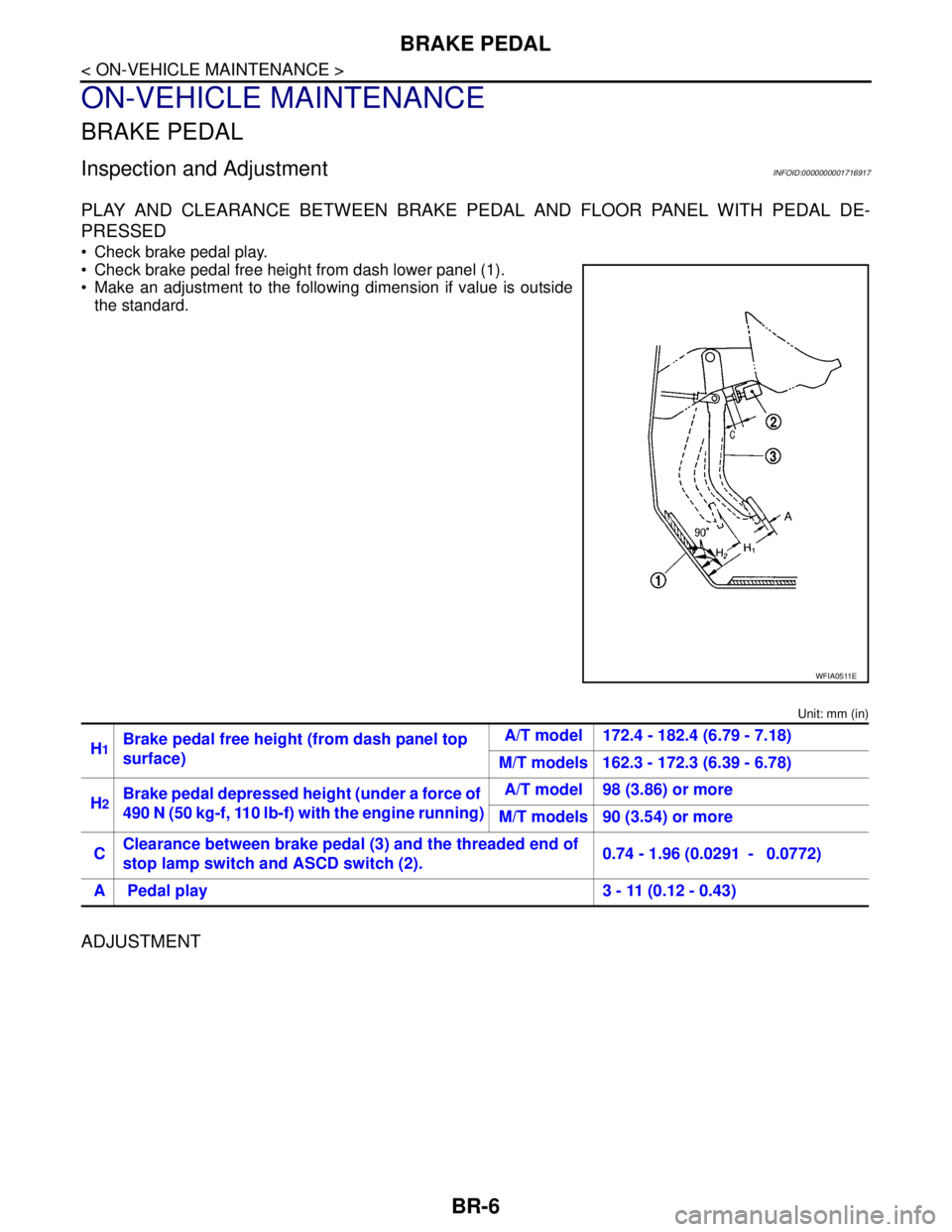
Check brake pedal play.
Check brake pedal free height from dash lower panel (1).
Make an adjustment to the following dimension if value is outside
the standard.
Unit: mm (in)
ADJUSTMENT
WFIA0511E
H1Brake pedal free height (from dash panel top
surface)A/T model 172.4 - 182.4 (6.79 - 7.18)
M/T models 162.3 - 172.3 (6.39 - 6.78)
H
2Brake pedal depressed height (under a force of
490 N (50 kg-f, 110 lb-f) with the engine running)A/T model 98 (3.86) or more
M/T models 90 (3.54) or more
CClearance between brake pedal (3) and the threaded end of
stop lamp switch and ASCD switch (2).0.74 - 1.96 (0.0291 - 0.0772)
A Pedal play 3 - 11 (0.12 - 0.43)
Page 199 of 5883
BRAKE PEDAL
BR-7
< ON-VEHICLE MAINTENANCE >
C
D
E
G
H
I
J
K
L
MA
B
BR
N
O
P
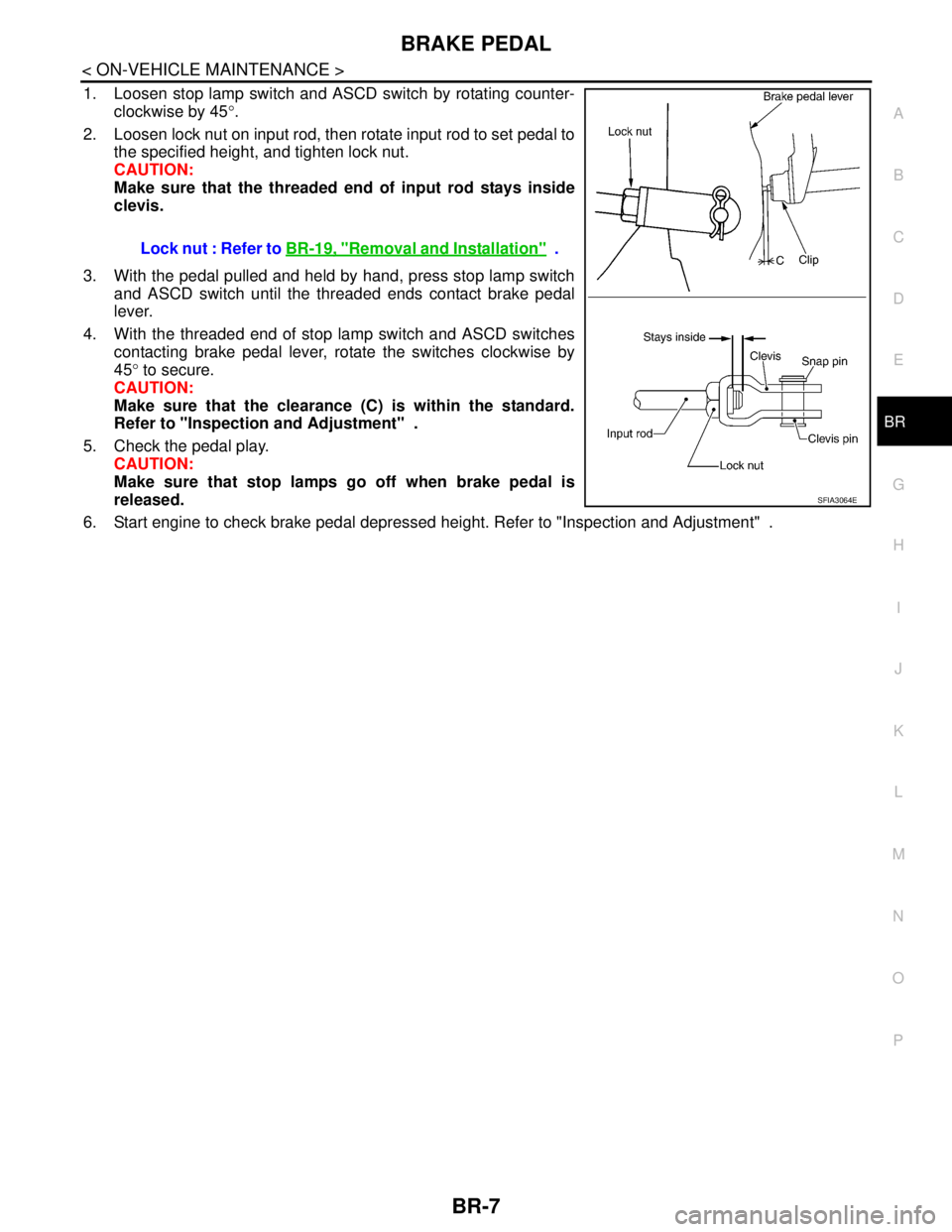
1. Loosen stop lamp switch and ASCD switch by rotating counter-
clockwise by 45°.
2. Loosen lock nut on input rod, then rotate input rod to set pedal to
the specified height, and tighten lock nut.
CAUTION:
Make sure that the threaded end of input rod stays inside
clevis.
3. With the pedal pulled and held by hand, press stop lamp switch
and ASCD switch until the threaded ends contact brake pedal
lever.
4. With the threaded end of stop lamp switch and ASCD switches
contacting brake pedal lever, rotate the switches clockwise by
45° to secure.
CAUTION:
Make sure that the clearance (C) is within the standard.
Refer to "Inspection and Adjustment" .
5. Check the pedal play.
CAUTION:
Make sure that stop lamps go off when brake pedal is
released.
6. Start engine to check brake pedal depressed height. Refer to "Inspection and Adjustment" . Lock nut : Refer to BR-19, "
Removal and Installation" .
SFIA3064E
Page 208 of 5883

BR-16
< ON-VEHICLE REPAIR >
BRAKE TUBE AND HOSE
1. Check brake hose, tube, and connections for fluid leaks, damage, twist, deformation, contact with other
parts, and loose connections.
2. While depressing pedal under a force of 785 N (80 kg-f, 177 lb-f) with the engine running for approxi-
mately 5 seconds, check for fluid leak from each part.
Page 211 of 5883
BRAKE BOOSTER
BR-19
< ON-VEHICLE REPAIR >
C
D
E
G
H
I
J
K
L
MA
B
BR
N
O
P
BRAKE BOOSTER
On Board InspectionINFOID:0000000001716999
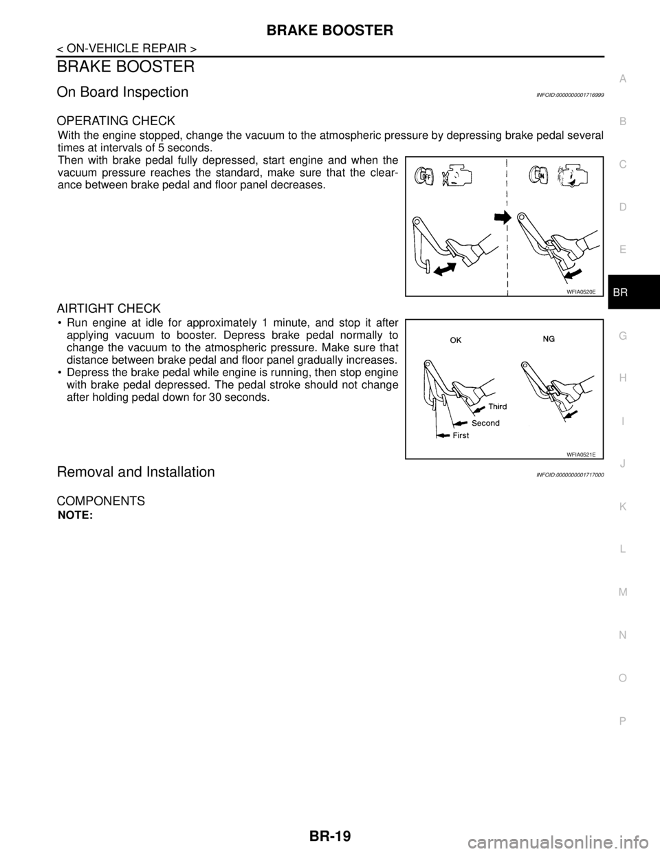
OPERATING CHECK
With the engine stopped, change the vacuum to the atmospheric pressure by depressing brake pedal several
times at intervals of 5 seconds.
Then with brake pedal fully depressed, start engine and when the
vacuum pressure reaches the standard, make sure that the clear-
ance between brake pedal and floor panel decreases.
AIRTIGHT CHECK
Run engine at idle for approximately 1 minute, and stop it after
applying vacuum to booster. Depress brake pedal normally to
change the vacuum to the atmospheric pressure. Make sure that
distance between brake pedal and floor panel gradually increases.
Depress the brake pedal while engine is running, then stop engine
with brake pedal depressed. The pedal stroke should not change
after holding pedal down for 30 seconds.
Removal and InstallationINFOID:0000000001717000
COMPONENTS
NOTE:
WFIA0520E
WFIA0521E
Page 214 of 5883
BR-22
< ON-VEHICLE REPAIR >
VACUUM LINES
VACUUM LINES
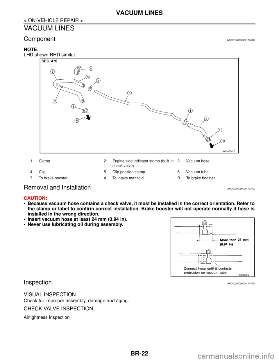
ComponentINFOID:0000000001717001
NOTE:
LHD shown RHD similar.
Removal and InstallationINFOID:0000000001717002
CAUTION:
Because vacuum hose contains a check valve, it must be installed in the correct orientation. Refer to
the stamp or label to confirm correct installation. Brake booster will not operate normally if hose is
installed in the wrong direction.
Insert vacuum hose at least 24 mm (0.94 in).
Never use lubricating oil during assembly.
InspectionINFOID:0000000001717003
VISUAL INSPECTION
Check for improper assembly, damage and aging.
CHECK VALVE INSPECTION
Airtightness Inspection
1. Clamp 2. Engine side indicator stamp (built-in
check valve)3. Vacuum hose
4. Clip 5. Clip position stamp 6. Vacuum tube
7. To brake booster A. To intake manifold B. To brake booster
WFIA0541E
SBR225B
Page 215 of 5883
VACUUM LINES
BR-23
< ON-VEHICLE REPAIR >
C
D
E
G
H
I
J
K
L
MA
B
BR
N
O
P
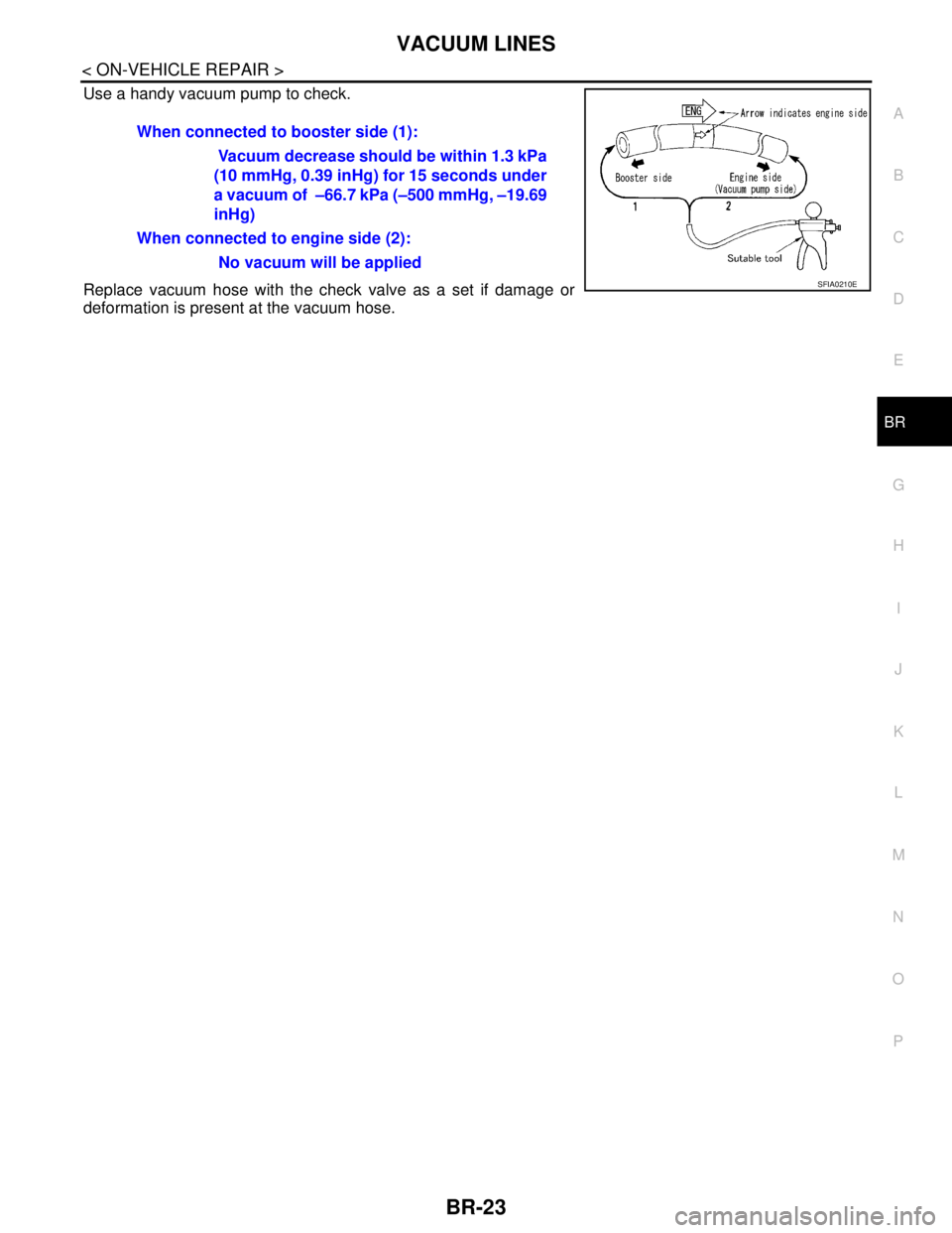
Use a handy vacuum pump to check.
Replace vacuum hose with the check valve as a set if damage or
deformation is present at the vacuum hose.When connected to booster side (1):
Vacuum decrease should be within 1.3 kPa
(10 mmHg, 0.39 inHg) for 15 seconds under
a vacuum of –66.7 kPa (–500 mmHg, –19.69
inHg)
When connected to engine side (2):
No vacuum will be applied
SFIA0210E
Page 232 of 5883

BR-40
< SERVICE DATA AND SPECIFICATIONS (SDS)
SERVICE DATA AND SPECIFICATIONS (SDS)
SERVICE DATA AND SPECIFICATIONS (SDS)
SERVICE DATA AND SPECIFICATIONS (SDS)
General SpecificationINFOID:0000000001716911
Brake PedalINFOID:0000000001716912
Unit: mm (in)
Check ValveINFOID:0000000001716913
Brake BoosterINFOID:0000000001716914
Vacuum type
Front Disc BrakeINFOID:0000000001716915
Unit: mm (in)
Front brake Brake model CLZ25VA
Cylinder bore diameter 57.2 mm (2.252 in)
Pad
Length × width × thickness125.6 mm × 46.0 mm × 9.5 mm
(4.945 in × 1.811 in × 0.374 in)
Rotor outer diameter × thickness 280 mm × 24.0 mm (11.02 in × 0.945 in)
Rear brake Brake model —
Cylinder bore diameter 34.93 mm (1.375 in)
Pad thickness 8.5 mm (0.335 in)
Rotor outer diameter × thickness292 mm × 9.0 mm
(11.50 in × 0.354 in)
Master cylinder Cylinder bore diameter 22.22 mm (0.875 in)
Control valve Valve model Electric brake force distribution
Brake booster Booster model C255
Diaphragm diameter 255 mm (10.04 in)
Recommended brake fluid Refer to MA-19
.
Brake pedal free height (from dash panel top surface)A/T model 172.4 - 182.4 (6.79 - 7.18)
M/T models 162.3 - 172.3 (6.39 - 6.78)
Brake pedal depressed height
[under a force of 490 N (50 kg-f, 110 lb-f) with the engine running]A/T model 98 (3.86) or more
M/T models 90 (3.54) or more
Clearance between brake pedal lever and the threaded end of stop lamp switch 0.74 - 1.96 (0.0291 - 0.0772)
Pedal play3 - 11 (0.12 - 0.43)
Vacuum leakage
[at vacuum of – 66.7 kPa (– 500 mmHg, – 19.69 inHg]Within 1.3 kPa (10 mmHg, 0.39 inHg) of vacuum for 15 seconds
Vacuum leakage
[at vacuum of – 66.7 kPa (– 500 mmHg, –19.69 inHg)]Within 3.3 kPa (25 mmHg, 0.98 inHg) of vacuum for 15 seconds
Input rod installation standard dimension 154 - 161 mm (6.06 - 6.34 in)
Brake modelCLZ25VA
Brake padStandard thickness (new) 9.5 (0.374)
Repair limit thickness 2.0 (0.079)