ckp NISSAN TIIDA 2007 Service Repair Manual
[x] Cancel search | Manufacturer: NISSAN, Model Year: 2007, Model line: TIIDA, Model: NISSAN TIIDA 2007Pages: 5883, PDF Size: 78.95 MB
Page 589 of 5883
DEF-38
< ON-VEHICLE REPAIR >
CONDENSER
CONDENSER
Exploded ViewINFOID:0000000001697577
Refer to DEF-38, "Exploded View".
Removal and InstallationINFOID:0000000001697578
REMOVAL
1. Remove the rear seat cushion and the rear seat back.
Refer to XX-XX, "*****"
.
2. Remove the rear kickplate, rear wheel well garnish and the rear pillar finisher.
Refer to XX-XX, "*****"
.
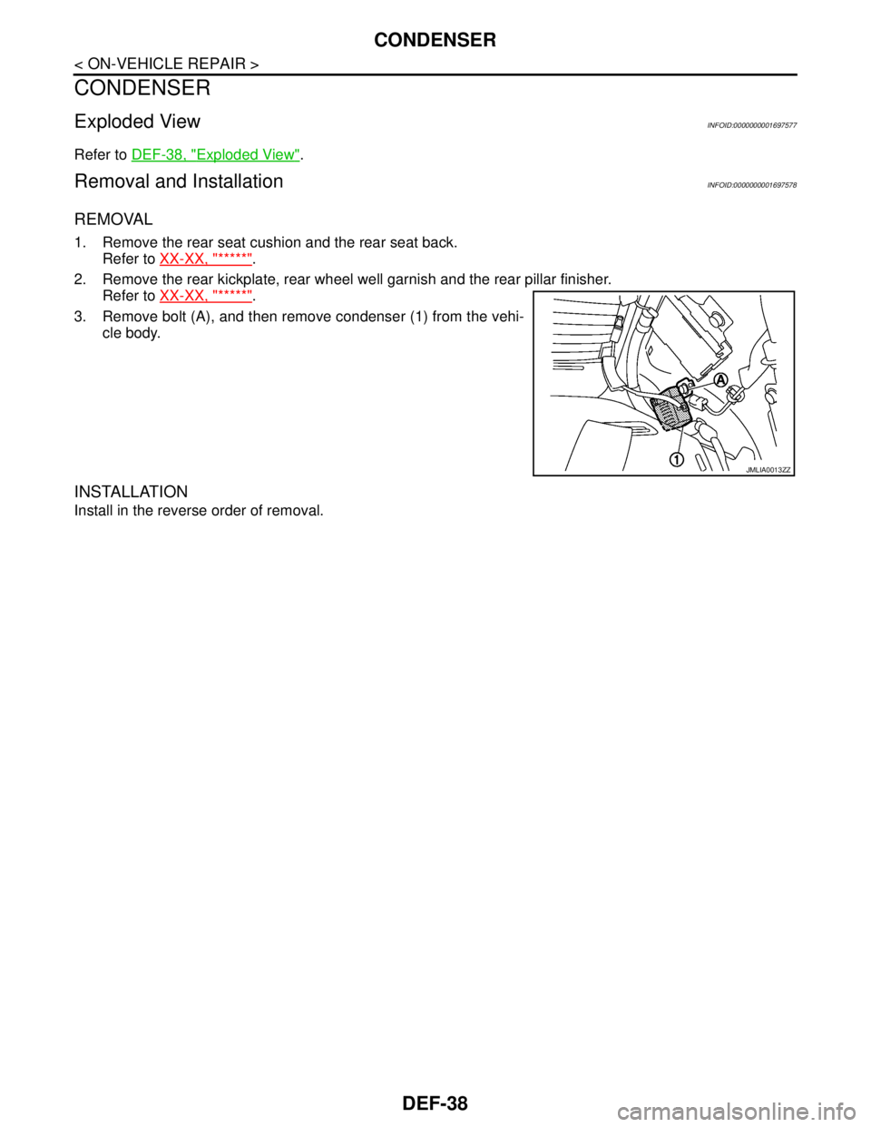
3. Remove bolt (A), and then remove condenser (1) from the vehi-
cle body.
INSTALLATION
Install in the reverse order of removal.
JMLIA0013ZZ
Page 1352 of 5883
EC-3
C
D
E
F
G
H
I
J
K
L
M
ECA
N
O
P
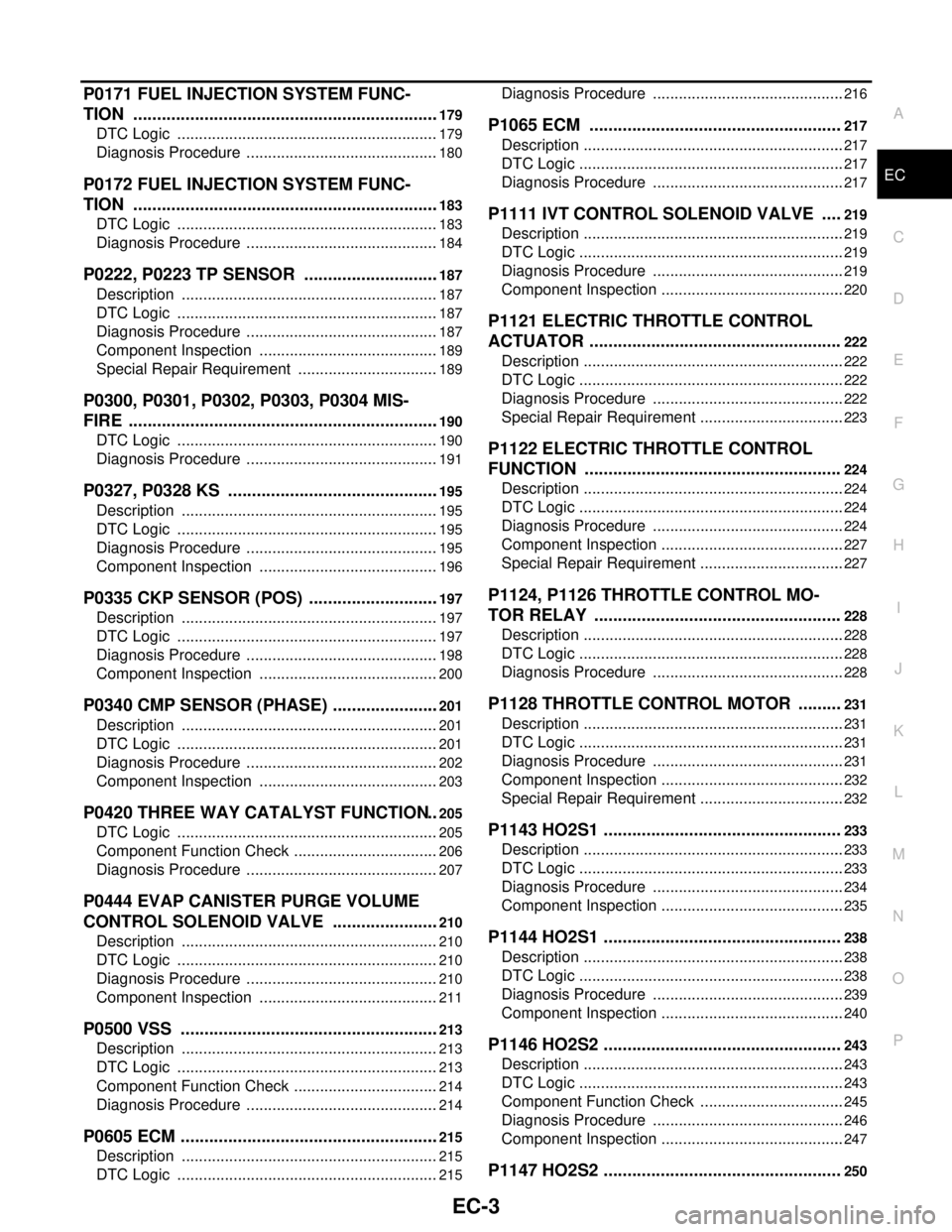
P0171 FUEL INJECTION SYSTEM FUNC-
TION .................................................................
179
DTC Logic .............................................................179
Diagnosis Procedure .............................................180
P0172 FUEL INJECTION SYSTEM FUNC-
TION .................................................................
183
DTC Logic .............................................................183
Diagnosis Procedure .............................................184
P0222, P0223 TP SENSOR .............................187
Description ............................................................187
DTC Logic .............................................................187
Diagnosis Procedure .............................................187
Component Inspection ..........................................189
Special Repair Requirement .................................189
P0300, P0301, P0302, P0303, P0304 MIS-
FIRE ..................................................................
190
DTC Logic .............................................................190
Diagnosis Procedure .............................................191
P0327, P0328 KS .............................................195
Description ............................................................195
DTC Logic .............................................................195
Diagnosis Procedure .............................................195
Component Inspection ..........................................196
P0335 CKP SENSOR (POS) ............................197
Description ............................................................197
DTC Logic .............................................................197
Diagnosis Procedure .............................................198
Component Inspection ..........................................200
P0340 CMP SENSOR (PHASE) .......................201
Description ............................................................201
DTC Logic .............................................................201
Diagnosis Procedure .............................................202
Component Inspection ..........................................203
P0420 THREE WAY CATALYST FUNCTION ..205
DTC Logic .............................................................205
Component Function Check ..................................206
Diagnosis Procedure .............................................207
P0444 EVAP CANISTER PURGE VOLUME
CONTROL SOLENOID VALVE .......................
210
Description ............................................................210
DTC Logic .............................................................210
Diagnosis Procedure .............................................210
Component Inspection ..........................................211
P0500 VSS .......................................................213
Description ............................................................213
DTC Logic .............................................................213
Component Function Check ..................................214
Diagnosis Procedure .............................................214
P0605 ECM .......................................................215
Description ............................................................215
DTC Logic .............................................................215
Diagnosis Procedure .............................................216
P1065 ECM .....................................................217
Description .............................................................217
DTC Logic ..............................................................217
Diagnosis Procedure .............................................217
P1111 IVT CONTROL SOLENOID VALVE ....219
Description .............................................................219
DTC Logic ..............................................................219
Diagnosis Procedure .............................................219
Component Inspection ...........................................220
P1121 ELECTRIC THROTTLE CONTROL
ACTUATOR .....................................................
222
Description .............................................................222
DTC Logic ..............................................................222
Diagnosis Procedure .............................................222
Special Repair Requirement ..................................223
P1122 ELECTRIC THROTTLE CONTROL
FUNCTION ......................................................
224
Description .............................................................224
DTC Logic ..............................................................224
Diagnosis Procedure .............................................224
Component Inspection ...........................................227
Special Repair Requirement ..................................227
P1124, P1126 THROTTLE CONTROL MO-
TOR RELAY ....................................................
228
Description .............................................................228
DTC Logic ..............................................................228
Diagnosis Procedure .............................................228
P1128 THROTTLE CONTROL MOTOR .........231
Description .............................................................231
DTC Logic ..............................................................231
Diagnosis Procedure .............................................231
Component Inspection ...........................................232
Special Repair Requirement ..................................232
P1143 HO2S1 ..................................................233
Description .............................................................233
DTC Logic ..............................................................233
Diagnosis Procedure .............................................234
Component Inspection ...........................................235
P1144 HO2S1 ..................................................238
Description .............................................................238
DTC Logic ..............................................................238
Diagnosis Procedure .............................................239
Component Inspection ...........................................240
P1146 HO2S2 ..................................................243
Description .............................................................243
DTC Logic ..............................................................243
Component Function Check ..................................245
Diagnosis Procedure .............................................246
Component Inspection ...........................................247
P1147 HO2S2 ..................................................250
Page 1356 of 5883
EC-7
C
D
E
F
G
H
I
J
K
L
M
ECA
N
O
P Diagnosis Procedure .............................................
503
Component Inspection ..........................................504
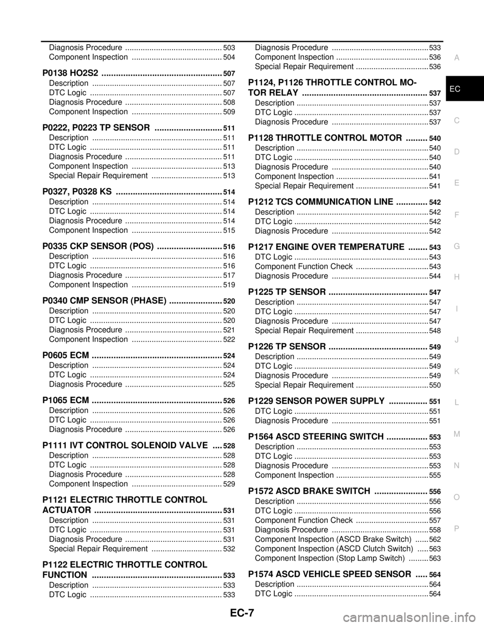
P0138 HO2S2 ...................................................507
Description ............................................................507
DTC Logic .............................................................507
Diagnosis Procedure .............................................508
Component Inspection ..........................................509
P0222, P0223 TP SENSOR .............................511
Description ............................................................511
DTC Logic .............................................................511
Diagnosis Procedure .............................................511
Component Inspection ..........................................513
Special Repair Requirement .................................513
P0327, P0328 KS .............................................514
Description ............................................................514
DTC Logic .............................................................514
Diagnosis Procedure .............................................514
Component Inspection ..........................................515
P0335 CKP SENSOR (POS) ............................516
Description ............................................................516
DTC Logic .............................................................516
Diagnosis Procedure .............................................517
Component Inspection ..........................................519
P0340 CMP SENSOR (PHASE) .......................520
Description ............................................................520
DTC Logic .............................................................520
Diagnosis Procedure .............................................521
Component Inspection ..........................................522
P0605 ECM .......................................................524
Description ............................................................524
DTC Logic .............................................................524
Diagnosis Procedure .............................................525
P1065 ECM .......................................................526
Description ............................................................526
DTC Logic .............................................................526
Diagnosis Procedure .............................................526
P1111 IVT CONTROL SOLENOID VALVE .....528
Description ............................................................528
DTC Logic .............................................................528
Diagnosis Procedure .............................................528
Component Inspection ..........................................529
P1121 ELECTRIC THROTTLE CONTROL
ACTUATOR ......................................................
531
Description ............................................................531
DTC Logic .............................................................531
Diagnosis Procedure .............................................531
Special Repair Requirement .................................532
P1122 ELECTRIC THROTTLE CONTROL
FUNCTION .......................................................
533
Description ............................................................533
DTC Logic .............................................................533
Diagnosis Procedure .............................................533
Component Inspection ...........................................536
Special Repair Requirement ..................................536
P1124, P1126 THROTTLE CONTROL MO-
TOR RELAY ....................................................
537
Description .............................................................537
DTC Logic ..............................................................537
Diagnosis Procedure .............................................537
P1128 THROTTLE CONTROL MOTOR .........540
Description .............................................................540
DTC Logic ..............................................................540
Diagnosis Procedure .............................................540
Component Inspection ...........................................541
Special Repair Requirement ..................................541
P1212 TCS COMMUNICATION LINE .............542
Description .............................................................542
DTC Logic ..............................................................542
Diagnosis Procedure .............................................542
P1217 ENGINE OVER TEMPERATURE ........543
DTC Logic ..............................................................543
Component Function Check ..................................543
Diagnosis Procedure .............................................544
P1225 TP SENSOR .........................................547
Description .............................................................547
DTC Logic ..............................................................547
Diagnosis Procedure .............................................547
Special Repair Requirement ..................................548
P1226 TP SENSOR .........................................549
Description .............................................................549
DTC Logic ..............................................................549
Diagnosis Procedure .............................................549
Special Repair Requirement ..................................550
P1229 SENSOR POWER SUPPLY ................551
DTC Logic ..............................................................551
Diagnosis Procedure .............................................551
P1564 ASCD STEERING SWITCH .................553
Description .............................................................553
DTC Logic ..............................................................553
Diagnosis Procedure .............................................553
Component Inspection ...........................................555
P1572 ASCD BRAKE SWITCH ......................556
Description .............................................................556
DTC Logic ..............................................................556
Component Function Check ..................................557
Diagnosis Procedure .............................................558
Component Inspection (ASCD Brake Switch) .......562
Component Inspection (ASCD Clutch Switch) ......563
Component Inspection (Stop Lamp Switch) ..........563
P1574 ASCD VEHICLE SPEED SENSOR .....564
Description .............................................................564
DTC Logic ..............................................................564
Page 1360 of 5883
EC-11
C
D
E
F
G
H
I
J
K
L
M
ECA
N
O
P
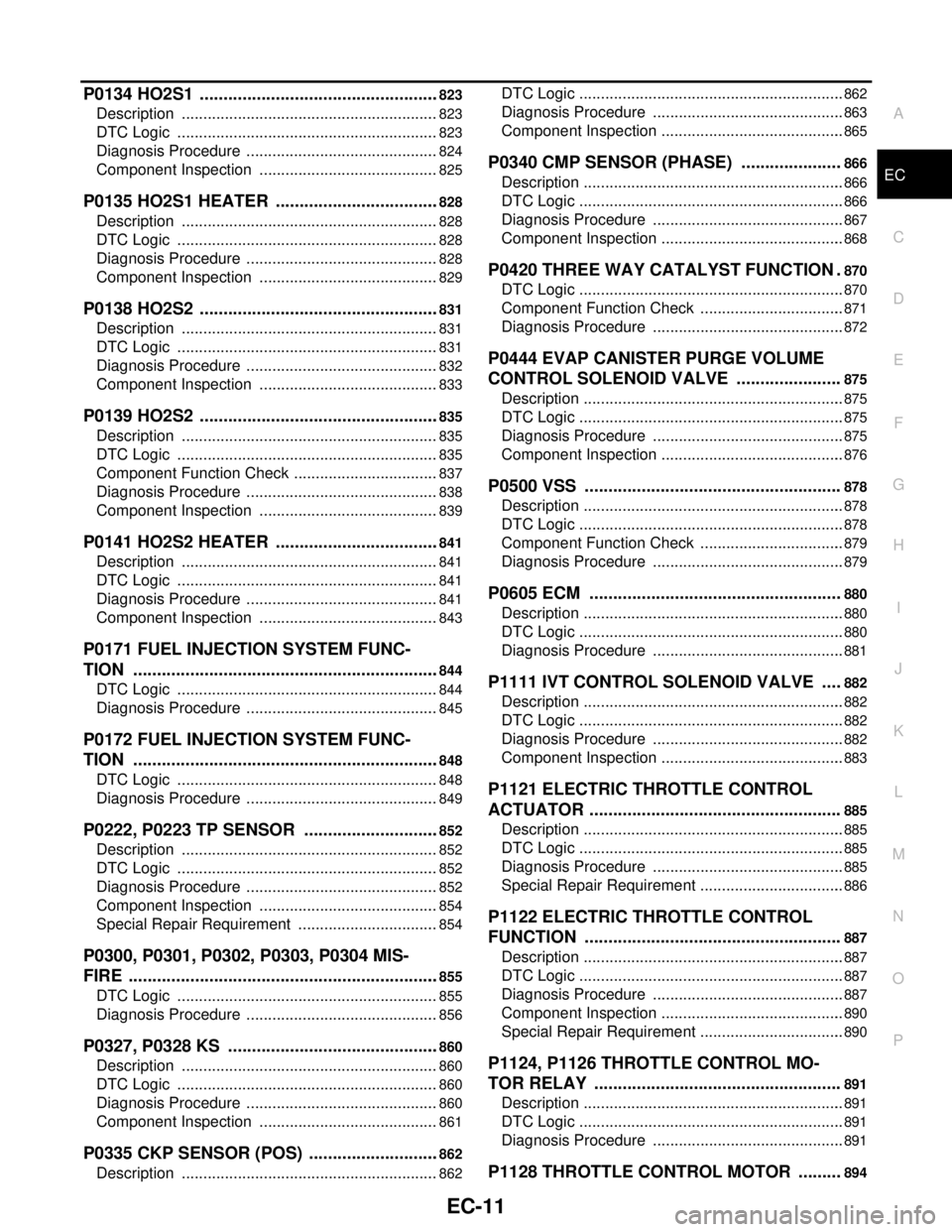
P0134 HO2S1 ...................................................823
Description ............................................................823
DTC Logic .............................................................823
Diagnosis Procedure .............................................824
Component Inspection ..........................................825
P0135 HO2S1 HEATER ...................................828
Description ............................................................828
DTC Logic .............................................................828
Diagnosis Procedure .............................................828
Component Inspection ..........................................829
P0138 HO2S2 ...................................................831
Description ............................................................831
DTC Logic .............................................................831
Diagnosis Procedure .............................................832
Component Inspection ..........................................833
P0139 HO2S2 ...................................................835
Description ............................................................835
DTC Logic .............................................................835
Component Function Check ..................................837
Diagnosis Procedure .............................................838
Component Inspection ..........................................839
P0141 HO2S2 HEATER ...................................841
Description ............................................................841
DTC Logic .............................................................841
Diagnosis Procedure .............................................841
Component Inspection ..........................................843
P0171 FUEL INJECTION SYSTEM FUNC-
TION .................................................................
844
DTC Logic .............................................................844
Diagnosis Procedure .............................................845
P0172 FUEL INJECTION SYSTEM FUNC-
TION .................................................................
848
DTC Logic .............................................................848
Diagnosis Procedure .............................................849
P0222, P0223 TP SENSOR .............................852
Description ............................................................852
DTC Logic .............................................................852
Diagnosis Procedure .............................................852
Component Inspection ..........................................854
Special Repair Requirement .................................854
P0300, P0301, P0302, P0303, P0304 MIS-
FIRE ..................................................................
855
DTC Logic .............................................................855
Diagnosis Procedure .............................................856
P0327, P0328 KS .............................................860
Description ............................................................860
DTC Logic .............................................................860
Diagnosis Procedure .............................................860
Component Inspection ..........................................861
P0335 CKP SENSOR (POS) ............................862
Description ............................................................862
DTC Logic ..............................................................862
Diagnosis Procedure .............................................863
Component Inspection ...........................................865
P0340 CMP SENSOR (PHASE) .....................866
Description .............................................................866
DTC Logic ..............................................................866
Diagnosis Procedure .............................................867
Component Inspection ...........................................868
P0420 THREE WAY CATALYST FUNCTION .870
DTC Logic ..............................................................870
Component Function Check ..................................871
Diagnosis Procedure .............................................872
P0444 EVAP CANISTER PURGE VOLUME
CONTROL SOLENOID VALVE ......................
875
Description .............................................................875
DTC Logic ..............................................................875
Diagnosis Procedure .............................................875
Component Inspection ...........................................876
P0500 VSS ......................................................878
Description .............................................................878
DTC Logic ..............................................................878
Component Function Check ..................................879
Diagnosis Procedure .............................................879
P0605 ECM .....................................................880
Description .............................................................880
DTC Logic ..............................................................880
Diagnosis Procedure .............................................881
P1111 IVT CONTROL SOLENOID VALVE ....882
Description .............................................................882
DTC Logic ..............................................................882
Diagnosis Procedure .............................................882
Component Inspection ...........................................883
P1121 ELECTRIC THROTTLE CONTROL
ACTUATOR .....................................................
885
Description .............................................................885
DTC Logic ..............................................................885
Diagnosis Procedure .............................................885
Special Repair Requirement ..................................886
P1122 ELECTRIC THROTTLE CONTROL
FUNCTION ......................................................
887
Description .............................................................887
DTC Logic ..............................................................887
Diagnosis Procedure .............................................887
Component Inspection ...........................................890
Special Repair Requirement ..................................890
P1124, P1126 THROTTLE CONTROL MO-
TOR RELAY ....................................................
891
Description .............................................................891
DTC Logic ..............................................................891
Diagnosis Procedure .............................................891
P1128 THROTTLE CONTROL MOTOR .........894
Page 1363 of 5883
EC-14
BASIC INSPECTION : Special Repair Require-
ment (TEST 1: Low Pressure Fuel Supply System
Check) .................................................................
1043
BASIC INSPECTION : Special Repair Require-
ment (TEST 2: Internal Fuel Transfer Pump
Check) .................................................................
1044
BASIC INSPECTION : Special Repair Require-
ment [TEST 3: High Pressure Supply Pump (Pres-
sure Control Valve) Check] ..................................
1044
BASIC INSPECTION : Special Repair Require-
ment [TEST 4: High Pressure Supply Pump (Vol-
umetric Control Valve) Check] .............................
1045
BASIC INSPECTION : Special Repair Require-
ment (TEST 5: Rail High Pressure Regulation
Check) .................................................................
1048
BASIC INSPECTION : Special Repair Require-
ment (TEST 6: Major Leak in Fuel Injectors/Fuel
Injectors Open) ....................................................
1052
BASIC INSPECTION : Special Repair Require-
ment (TEST 7: Incorrect Fuel Injection Quantity)
1053
ADDITIONAL SERVICE WHEN REPLACING
CONTROL UNIT .....................................................
1054
ADDITIONAL SERVICE WHEN REPLACING
CONTROL UNIT : Description .............................
1054
ADDITIONAL SERVICE WHEN REPLACING
CONTROL UNIT : Special Repair Requirement ..
1054
EGR VOLUME CONTROL VALVE CLOSED POSI-
TION LEARNING ...................................................
1055
EGR VOLUME CONTROL VALVE CLOSED PO-
SITION LEARNING : Description ........................
1055
EGR VOLUME CONTROL VALVE CLOSED PO-
SITION LEARNING : Special Repair Requirement
1055
FUNCTION DIAGNOSIS ..........................1057
ENGINE CONTROL SYSTEM ........................1057
System Diagram ..................................................1057
System Description ..............................................1058
Component Parts Location ..................................1058
Component Description .......................................1062
FUEL INJECTION CONTROL ........................1063
System Description ..............................................1063
Component Parts Location ..................................1065
TURBOCHARGER BOOST CONTROL .........1070
Vacuum Hose Drawing ........................................1070
System Description ..............................................1070
Component Parts Location ..................................1071
EGR SYSTEM .................................................1076
System Description ..............................................1076
Component Parts Location ..................................1076
IDLE SPEED CONTROL ................................1081
System Diagram ..................................................1081
System Description ..............................................1081
Component Parts Location ..................................1082
ENGINE TORQUE CONTROL .......................1087
System Description ..............................................1087
Component Parts Location ..................................1087
GLOW CONTROL ..........................................1092
System Description ..............................................1092
Component Parts Location ..................................1092
COOLING FAN CONTROL ............................1097
System Description ..............................................1097
Component Parts Location ..................................1098
CAN COMMUNICATION ................................1103
System Description ..............................................1103
ON BOARD DIAGNOSTIC (OBD) SYSTEM ..1104
Diagnosis Description ..........................................1104
COMPONENT DIAGNOSIS .....................1106
POWER SUPPLY AND GROUND CIRCUIT ..1106
Diagnosis Procedure ............................................1106
P0001 FUEL PUMP ........................................1109
DTC Logic ............................................................1109
Diagnosis Procedure ............................................1109
Component Inspection .........................................1110
P0002 FUEL PUMP ........................................1111
DTC Logic ............................................................1111
Diagnosis Procedure ............................................1111
Component Inspection .........................................1112
P0016 CKP - CMP CORRELATION ...............1113
DTC Logic ............................................................1113
Diagnosis Procedure ............................................1113
Component Inspection .........................................1114
P0045 TC BOOST CONTROL SOLENOID
VALVE ............................................................
1116
DTC Logic ............................................................1116
Diagnosis Procedure ............................................1116
Component Inspection .........................................1117
P0069 TC BOOST SENSOR, BARO SENSOR
CORRELATION ..............................................
1118
DTC Logic ............................................................1118
Diagnosis Procedure ............................................1118
Component Inspection .........................................1119
P0087 FUEL PUMP ........................................1120
DTC Logic ............................................................1120
Diagnosis Procedure ............................................1120
P0090 FUEL PUMP ........................................1122
DTC Logic ............................................................1122
Diagnosis Procedure ............................................1122
Component Inspection .........................................1123
P0100 MAF SENSOR .....................................1124
Description ...........................................................1124
DTC Logic ............................................................1124
Page 1364 of 5883
EC-15
C
D
E
F
G
H
I
J
K
L
M
ECA
N
O
P Diagnosis Procedure ...........................................
1124
Component Inspection ........................................1125
P0101 MAF SENSOR .....................................1127
Description ..........................................................1127
DTC Logic ...........................................................1127
Diagnosis Procedure ...........................................1127
Component Inspection ........................................1129
P0110 IAT SENSOR .......................................1130
Description ..........................................................1130
DTC Logic ...........................................................1130
Diagnosis Procedure ...........................................1130
Component Inspection ........................................1131
P0115 ECT SENSOR .....................................1132
Description ..........................................................1132
DTC Logic ...........................................................1132
Diagnosis Procedure ...........................................1132
Component Inspection ........................................1133
P0120 ELECTRIC THROTTLE CONTROL
ACTUATOR ....................................................
1134
Description ..........................................................1134
DTC Logic ...........................................................1134
Diagnosis Procedure ...........................................1134
P0180 FPT SENSOR ......................................1136
Description ..........................................................1136
DTC Logic ...........................................................1136
Diagnosis Procedure ...........................................1136
Component Inspection ........................................1137
P0190 FRP SENSOR .....................................1138
Description ..........................................................1138
DTC Logic ...........................................................1138
Diagnosis Procedure ...........................................1138
Component Inspection ........................................1139
P0200 FUEL INJECTOR ................................1140
DTC Logic ...........................................................1140
Diagnosis Procedure ...........................................1140
Component Inspection ........................................1141
P0201, P0202, P0203, P0204 FUEL INJEC-
TOR ................................................................
1142
DTC Logic ...........................................................1142
Diagnosis Procedure ...........................................1142
Component Inspection ........................................1143
P0225 APP SENSOR .....................................1144
Description ..........................................................1144
DTC Logic ...........................................................1144
Diagnosis Procedure ...........................................1144
Component Inspection ........................................1146
P0235 TC BOOST SENSOR ..........................1147
Description ..........................................................1147
DTC Logic ...........................................................1147
Diagnosis Procedure ...........................................1147
Component Inspection ........................................1148
P0335 CKP SENSOR .....................................1149
DTC Logic ............................................................1149
Diagnosis Procedure ...........................................1149
Component Inspection .........................................1150
P0340 CMP SENSOR ....................................1151
DTC Logic ............................................................1151
Diagnosis Procedure ...........................................1151
Component Inspection .........................................1152
P0380 GLOW RELAY ....................................1154
DTC Logic ............................................................1154
Diagnosis Procedure ...........................................1154
P0381 GLOW CONTROL SYSTEM ...............1156
DTC Logic ............................................................1156
Diagnosis Procedure ...........................................1156
Component Inspection .........................................1157
P0409 EGR VOLUME CONTROL VALVE
CONTROL POSITION SENSOR ....................
1158
DTC Logic ............................................................1158
Diagnosis Procedure ...........................................1158
P0487 EGR VOLUME CONTROL VALVE ....1160
DTC Logic ............................................................1160
Diagnosis Procedure ...........................................1160
Component Inspection .........................................1161
P0488 EGR SYSTEM .....................................1162
DTC Logic ............................................................1162
Diagnosis Procedure ...........................................1162
Component Inspection .........................................1164
P0500 VSS .....................................................1165
Description ...........................................................1165
DTC Logic ............................................................1165
Diagnosis Procedure ...........................................1165
P0530 REFRIGERANT PRESSURE SENSOR
1166
Description ...........................................................1166
DTC Logic ............................................................1166
Diagnosis Procedure ...........................................1166
P0560 BATTERY VOLTAGE .........................1168
DTC Logic ............................................................1168
Diagnosis Procedure ...........................................1168
P0571 ASCD BRAKE SWITCH .....................1171
DTC Logic ............................................................1171
Diagnosis Procedure ...........................................1171
Component Inspection .........................................1172
P0575 ASCD STEERING SWITCH ................1174
Description ...........................................................1174
DTC Logic ............................................................1174
Diagnosis Procedure ...........................................1174
Component Inspection (ASCD Switch) ................1176
Component Inspection (ASCD Steering Switch) .1176
Page 1539 of 5883

EC-190
< COMPONENT DIAGNOSIS >[HR16DE (WITH EURO-OBD)]
P0300, P0301, P0302, P0303, P0304 MISFIRE
P0300, P0301, P0302, P0303, P0304 MISFIRE
DTC LogicINFOID:0000000001670954
DTC DETECTION LOGIC
When a misfire occurs, engine speed will fluctuate. If the engine speed fluctuates enough to cause the crank-
shaft position (CKP) sensor (POS) signal to vary, ECM can determine that a misfire is occurring.
The misfire detection logic consists of the following two conditions.
1. One Trip Detection Logic (Three Way Catalyst Damage)
On the 1st trip that a misfire condition occurs that can damage the three way catalyst (TWC) due to over-
heating, the MI will blink.
When a misfire condition occurs, the ECM monitors the CKP sensor signal every 200 engine revolutions
for a change.
When the misfire condition decreases to a level that will not damage the TWC, the MI will turn off.
If another misfire condition occurs that can damage the TWC on a second trip, the MI will blink.
When the misfire condition decreases to a level that will not damage the TWC, the MI will remain on.
If another misfire condition occurs that can damage the TWC, the MI will begin to blink again.
2. Two Trip Detection Logic (Exhaust quality deterioration)
For misfire conditions that will not damage the TWC (but will affect vehicle emissions), the MI will only light
when the misfire is detected on a second trip. During this condition, the ECM monitors the CKP sensor
signal every 1,000 engine revolutions.
A misfire malfunction can be detected on any one cylinder or on multiple cylinders.
DTC CONFIRMATION PROCEDURE
1.PRECONDITIONING
If DTC Confirmation Procedure has been previously conducted, always turn ignition switch OFF and wait at
least 10 seconds before conducting the next test.
>> GO TO 2.
2.PERFORM DTC CONFIRMATION PROCEDURE-I
1. Start engine and warm it up to normal operating temperature.
2. Turn ignition switch OFF and wait at least 10 seconds.
3. Restart engine and let it idle for about 15 minutes.
4. Check 1st trip DTC.
Is 1st trip DTC detected?
YES >> Go to EC-191, "Diagnosis Procedure".
NO >> GO TO 3.
3.PERFORM DTC CONFIRMATION PROCEDURE-II
1. Turn ignition switch OFF and wait at least 10 seconds.
Sensor Input signal to ECM ECM function
Crankshaft position sensor (POS) Engine speed On board diagnosis of misfire
DTC No. Trouble diagnosis name DTC detecting condition Possible cause
P0300 Multiple cylinder misfire detected Multiple cylinder misfire. Improper spark plug
Insufficient compression
Incorrect fuel pressure
The fuel injector circuit is open or shorted
Fuel injector
Intake air leak
The ignition signal circuit is open or shorted
Lack of fuel
Signal plate
Heated oxygen sensor 1
Incorrect PCV hose connection P0301 No.1 cylinder misfire detected No. 1 cylinder misfires.
P0302 No. 2 cylinder misfire detected No. 2 cylinder misfires.
P0303 No. 3 cylinder misfire detected No. 3 cylinder misfires.
P0304 No. 4 cylinder misfire detected No. 4 cylinder misfires.
Page 1546 of 5883

P0335 CKP SENSOR (POS)
EC-197
< COMPONENT DIAGNOSIS >[HR16DE (WITH EURO-OBD)]
C
D
E
F
G
H
I
J
K
L
MA
EC
N
P O
P0335 CKP SENSOR (POS)
DescriptionINFOID:0000000001670960
The crankshaft position sensor (POS) is located on the oil pan facing
the gear teeth (cogs) of the signal plate. It detects the fluctuation of
the engine revolution.
The sensor consists of a permanent magnet and Hall IC.
When the engine is running, the high and low parts of the teeth
cause the gap with the sensor to change.
The changing gap causes the magnetic field near the sensor to
change.
Due to the changing magnetic field, the voltage from the sensor
changes.
The ECM receives the voltage signal and detects the fluctuation of
the engine revolution.
ECM receives the signals as shown in the figure.
DTC LogicINFOID:0000000001670961
DTC DETECTION LOGIC
DTC CONFIRMATION PROCEDURE
1.PRECONDITIONING
If DTC Confirmation Procedure has been previously conducted, always turn ignition switch OFF and wait at
least 10 seconds before conducting the next test.
TESTING CONDITION:
Before performing the following procedure, confirm that battery voltage is more than 10.5V with igni-
tion switch ON.
>> GO TO 2.
2.PERFORM DTC CONFIRMATION PROCEDURE
1. Start engine and let it idle for at least 5 seconds.
If engine does not start, crank engine for at least 2 seconds.
PBIA9209J
JMBIA0714GB
DTC No. Trouble diagnosis name DTC detecting condition Possible cause
P0335Crankshaft position sen-
sor (POS) circuit The crankshaft position sensor (POS) signal
is not detected by the ECM during the first
few seconds of engine cranking.
The proper pulse signal from the crankshaft
position sensor (POS) is not sent to ECM
while the engine is running.
The crankshaft position sensor (POS) signal
is not in the normal pattern during engine run-
ning. Harness or connectors
[Crankshaft position sensor (POS) circuit
is open or shorted.]
(Refrigerant pressure sensor circuit is
shorted.)
(Accelerator pedal position sensor 2 cir-
cuit is shorted.)
Crankshaft position sensor (POS)
Refrigerant pressure sensor
Accelerator pedal position sensor
(APPS 2)
Signal plate
Page 1547 of 5883

EC-198
< COMPONENT DIAGNOSIS >[HR16DE (WITH EURO-OBD)]
P0335 CKP SENSOR (POS)
2. Check 1st trip DTC.
Is 1st trip DTC detected?
YES >> Go to EC-198, "Diagnosis Procedure".
NO >> INSPECTION END
Diagnosis ProcedureINFOID:0000000001670962
1.CHECK GROUND CONNECTION
1. Turn ignition switch OFF.
2. Check ground connection E15. Refer to Ground Inspection in GI-58, "
Circuit Inspection".
Is the inspection result normal?
YES >> GO TO 2.
NO >> Repair or replace ground connection.
2.CHECK CRANKSHAFT POSITION (CKP) SENSOR (POS) POWER SUPPLY CIRCUIT-I
1. Disconnect crankshaft position (CKP) sensor (POS) harness connector.
2. Turn ignition switch ON.
3. Check the voltage between CKP sensor (POS) harness connector and ground.
Is the inspection result normal?
YES >> GO TO 8.
NO >> GO TO 3.
3.CHECK CRANKSHAFT POSITION (CKP) SENSOR (POS) POWER SUPPLY CIRCUIT-II
1. Turn ignition switch OFF.
2. Disconnect ECM harness connector.
3. Check the continuity between CKP sensor (POS) harness connector and ECM harness connector.
Is the inspection result normal?
YES >> GO TO 4.
NO >> Repair open circuit.
4.CHECK CRANKSHAFT POSITION (CKP) SENSOR (POS) POWER SUPPLY CIRCUIT-III
Check harness for short to power and short to ground, between the following terminals.
Is the inspection result normal?
YES >> GO TO 5.
NO >> Repair short to ground or short to power in harness or connectors.
5.CHECK REFRIGERANT PRESSURE SENSOR
Refer to EC-326, "
Diagnosis Procedure".
CKP sensor (POS)
Ground Voltage
Connector Terminal
F15 1 Ground Approx. 5V
CKP sensor (POS) ECM
Continuity
Connector Terminal Connector Terminal
F15 1 F11 75 Existed
ECM Sensor
Connector Terminal Name Connector Terminal
F1174 Refrigerant pressure sensor E17 3
75 CKP sensor (POS) F15 1
E16 102 APP sensor 2E12 (LHD models)
M204 (RHD models)5
Page 1548 of 5883

P0335 CKP SENSOR (POS)
EC-199
< COMPONENT DIAGNOSIS >[HR16DE (WITH EURO-OBD)]
C
D
E
F
G
H
I
J
K
L
MA
EC
N
P O
Is the inspection result normal?
YES >> GO TO 6.
NO >> Replace refrigerant pressure sensor.
6.CHECK APP SENSOR
Refer to EC-293, "
Component Inspection".
Is the inspection result normal?
YES >> GO TO 12.
NO >> GO TO 7.
7.REPLACE ACCELERATOR PEDAL ASSEMBLY
1. Replace accelerator pedal assembly.
2. Go to EC-26, "
ACCELERATOR PEDAL RELEASED POSITION LEARNING : Special Repair Require-
ment".
>> INSPECTION END
8.CHECK CKP SENSOR (POS) GROUND CIRCUIT FOR OPEN AND SHORT
1. Turn ignition switch OFF.
2. Disconnect ECM harness connector.
3. Check the continuity between CKP sensor (POS) harness connector and ECM harness connector.
4. Also check harness for short to ground and short to power.
Is the inspection result normal?
YES >> GO TO 9.
NO >> Repair open circuit or short to ground or short to power in harness or connectors.
9.CHECK CKP SENSOR (POS) INPUT SIGNAL CIRCUIT FOR OPEN AND SHORT
1. Check the continuity between CKP sensor (POS) harness connector and ECM harness connector.
2. Also check harness for short to ground and short to power.
Is the inspection result normal?
YES >> GO TO 10.
NO >> Repair open circuit or short to ground or short to power in harness or connectors.
10.CHECK CRANKSHAFT POSITION SENSOR (POS)
Refer to EC-200, "
Component Inspection".
Is the inspection result normal?
YES >> GO TO 11.
NO >> Replace crankshaft position sensor (POS).
11 .CHECK GEAR TOOTH
Visually check for chipping signal plate gear tooth.
Is the inspection result normal?
YES >> GO TO 12.
NO >> Replace the signal plate.
12.CHECK INTERMITTENT INCIDENT
Refer to GI-55, "
Intermittent Incident".
CKP sensor (POS) ECM
Continuity
Connector Terminal Connector Terminal
F15 2 F11 62 Existed
CKP sensor (POS) ECM
Continuity
Connector Terminal Connector Terminal
F15 3 F11 61 Existed