ckp NISSAN TIIDA 2007 Service Owner's Guide
[x] Cancel search | Manufacturer: NISSAN, Model Year: 2007, Model line: TIIDA, Model: NISSAN TIIDA 2007Pages: 5883, PDF Size: 78.95 MB
Page 2463 of 5883
EC-1114
< COMPONENT DIAGNOSIS >[K9K]
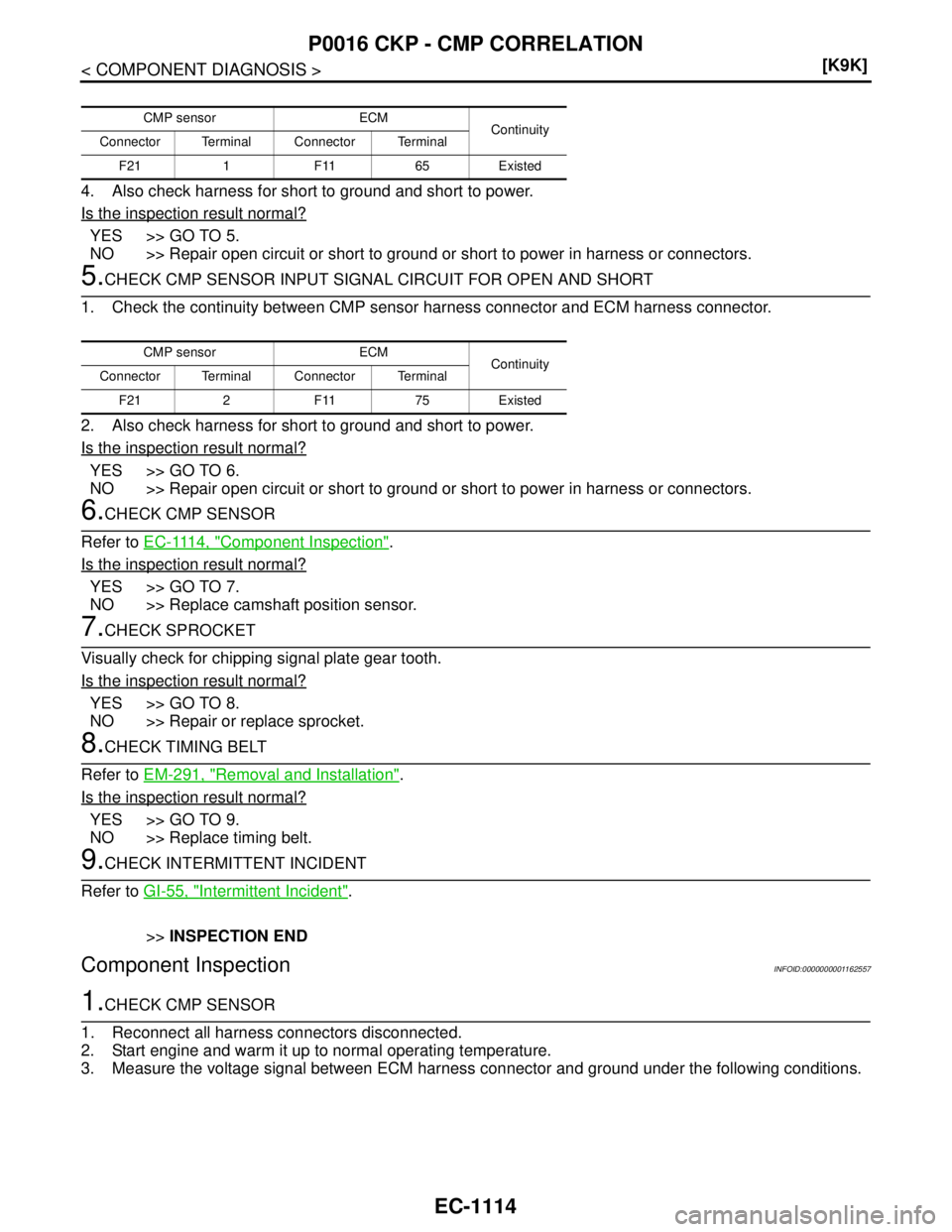
P0016 CKP - CMP CORRELATION
4. Also check harness for short to ground and short to power.
Is the inspection result normal?
YES >> GO TO 5.
NO >> Repair open circuit or short to ground or short to power in harness or connectors.
5.CHECK CMP SENSOR INPUT SIGNAL CIRCUIT FOR OPEN AND SHORT
1. Check the continuity between CMP sensor harness connector and ECM harness connector.
2. Also check harness for short to ground and short to power.
Is the inspection result normal?
YES >> GO TO 6.
NO >> Repair open circuit or short to ground or short to power in harness or connectors.
6.CHECK CMP SENSOR
Refer to EC-1114, "
Component Inspection".
Is the inspection result normal?
YES >> GO TO 7.
NO >> Replace camshaft position sensor.
7.CHECK SPROCKET
Visually check for chipping signal plate gear tooth.
Is the inspection result normal?
YES >> GO TO 8.
NO >> Repair or replace sprocket.
8.CHECK TIMING BELT
Refer to EM-291, "
Removal and Installation".
Is the inspection result normal?
YES >> GO TO 9.
NO >> Replace timing belt.
9.CHECK INTERMITTENT INCIDENT
Refer to GI-55, "
Intermittent Incident".
>>INSPECTION END
Component InspectionINFOID:0000000001162557
1.CHECK CMP SENSOR
1. Reconnect all harness connectors disconnected.
2. Start engine and warm it up to normal operating temperature.
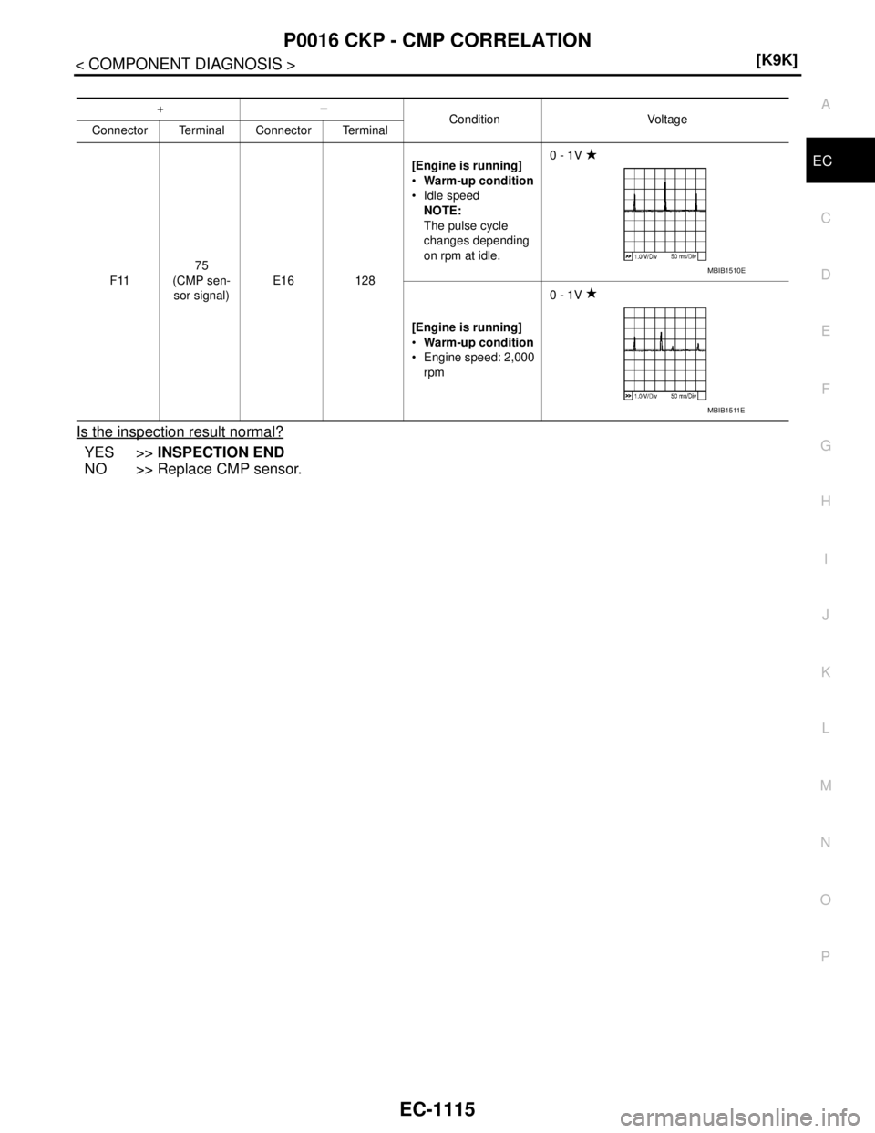
3. Measure the voltage signal between ECM harness connector and ground under the following conditions.
CMP sensor ECM
Continuity
Connector Terminal Connector Terminal
F21 1 F11 65 Existed
CMP sensor ECM
Continuity
Connector Terminal Connector Terminal
F21 2 F11 75 Existed
Page 2464 of 5883
P0016 CKP - CMP CORRELATION
EC-1115
< COMPONENT DIAGNOSIS >[K9K]
C
D
E
F
G
H
I
J
K
L
MA
EC
N
P O
Is the inspection result normal?
YES >>INSPECTION END
NO >> Replace CMP sensor.
+–
Condition Voltage
Connector Terminal Connector Terminal
F1175
(CMP sen-
sor signal)E16 128[Engine is running]
Warm-up condition
Idle speed
NOTE:
The pulse cycle
changes depending
on rpm at idle.0 - 1V
[Engine is running]
Warm-up condition
Engine speed: 2,000
rpm0 - 1V
MBIB1510E
MBIB1511E
Page 2498 of 5883
P0335 CKP SENSOR
EC-1149
< COMPONENT DIAGNOSIS >[K9K]
C
D
E
F
G
H
I
J
K
L
MA
EC
N
P O
P0335 CKP SENSOR
DTC LogicINFOID:0000000001162612
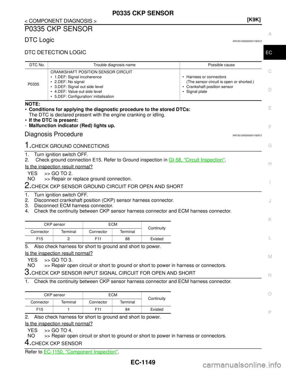
DTC DETECTION LOGIC
NOTE:
Conditions for applying the diagnostic procedure to the stored DTCs:
The DTC is declared present with the engine cranking or idling.
If the DTC is present:
-Malfunction indicator (Red) lights up.
Diagnosis ProcedureINFOID:0000000001162613
1.CHECK GROUND CONNECTIONS
1. Turn ignition switch OFF.
2. Check ground connection E15. Refer to Ground inspection in GI-58, "
Circuit Inspection".
Is the inspection result normal?
YES >> GO TO 2.
NO >> Repair or replace ground connection.
2.CHECK CKP SENSOR GROUND CIRCUIT FOR OPEN AND SHORT
1. Turn ignition switch OFF.
2. Disconnect crankshaft position (CKP) sensor harness connector.
3. Disconnect ECM harness connector.
4. Check the continuity between CKP sensor harness connector and ECM harness connector.
5. Also check harness for short to ground and short to power.
Is the inspection result normal?
YES >> GO TO 3.
NO >> Repair open circuit or short to ground or short to power in harness or connectors.
3.CHECK CKP SENSOR INPUT SIGNAL CIRCUIT FOR OPEN AND SHORT
1. Check the continuity between CKP sensor harness connector and ECM harness connector.
2. Also check harness for short to ground and short to power.
Is the inspection result normal?
YES >> GO TO 4.
NO >> Repair open circuit or short to ground or short to power in harness or connectors.
4.CHECK CKP SENSOR
Refer to EC-1150, "
Component Inspection".
DTC No. Trouble diagnosis name Possible cause
P0335CRANKSHAFT POSITION SENSOR CIRCUIT
1.DEF: Signal incoherence
2.DEF: No signal
3.DEF: Signal out side level
4.DEF: Value out side level
5.DEF: Configuration/ initialisation Harness or connectors
(The sensor circuit is open or shorted.)
Crankshaft position sensor
Signal plate
CKP sensor ECM
Continuity
Connector Terminal Connector Terminal
F15 2 F11 88 Existed
CKP sensor ECM
Continuity
Connector Terminal Connector Terminal
F15 1 F11 84 Existed
Page 2499 of 5883
EC-1150
< COMPONENT DIAGNOSIS >[K9K]
P0335 CKP SENSOR
Is the inspection result normal?
YES >> GO TO 5.
NO >> Replace crankshaft position sensor.
5.CHECK GEAR TOOTH
Visually check for chipping flywheel gear tooth.
Is the inspection result normal?
YES >> GO TO 6.
NO >> Replace signal plate.
6.CHECK INTERMITTENT INCIDENT
Refer to GI-55, "
Intermittent Incident".
>>INSPECTION END
Component InspectionINFOID:0000000001162614
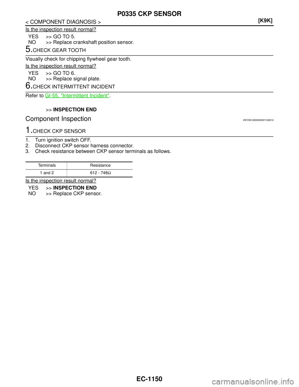
1.CHECK CKP SENSOR
1. Turn ignition switch OFF.
2. Disconnect CKP sensor harness connector.
3. Check resistance between CKP sensor terminals as follows.
Is the inspection result normal?
YES >>INSPECTION END
NO >> Replace CKP sensor.
Terminals Resistance
1 and 2 612 - 748Ω
Page 2573 of 5883
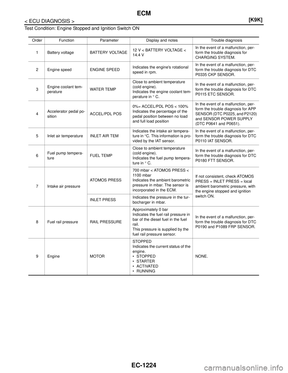
EC-1224
< ECU DIAGNOSIS >[K9K]
ECM
Test Condition: Engine Stopped and Ignition Switch ON
Order Function Parameter Display and notes Trouble diagnosis
1 Battery voltage BATTERY VOLTAGE12 V < BATTERY VOLTAGE <
14.4 VIn the event of a malfunction, per-
form the trouble diagnosis for
CHARGING SYSTEM.
2 Engine speed ENGINE SPEEDIndicates the engine's rotational
speed in rpm.In the event of a malfunction, per-
form the trouble diagnosis for DTC
P0335 CKP SENSOR.
3Engine coolant tem-
peratureWATER TEMPClose to ambient temperature
(cold engine).
Indicates the engine coolant tem-
perature in ° C.In the event of a malfunction, per-
form the trouble diagnosis for DTC
P0115 ETC SENSOR.
4Accelerator pedal po-
sitionACCEL/PDL POS0%= ACCEL/PDL POS < 100%
Indicates the percentage of the
pedal position between no load
and full load positionIn the event of a malfunction, per-
form the trouble diagnosis for APP
SENSOR (DTC P0225, and P2120)
and SENSOR POWER SUPPLY
(DTC P0641 and P0651).
5 Inlet air temperature INLET AIR TEMIndicates the intake air tempera-
ture in °C. This information is pro-
vided by the IAT sensor.In the event of a malfunction, per-
form the trouble diagnosis for DTC
P0110 IAT SENSOR.
6Fuel pump tempera-
tureFUEL TEMPClose to ambient temperature
(cold engine).
Indicates the fuel pump tempera-
ture in ° C.In the event of a malfunction, per-
form the trouble diagnosis for DTC
P0180 FTT SENSOR.
7 Intake air pressureATOMOS PRESS700 mbar < ATOMOS PRESS <
11 0 0 m b a r
Indicates the ambient barometric
pressure in mbar. The sensor is
incorporated in the ECM.If not consistent, check ATOMOS
PRESS = INLET PRESS = local
ambient barometric pressure, with
the engine stopped and ignition
switch ON.
INLET PRESSIndicates the pressure in the tur-
bocharger in mbar.
8 Fuel rail pressure RAIL PRESSUREApproximately 0 bar
Indicates the fuel rail pressure in
bar of the diesel fuel in the fuel
rail.
This pressure is supplied by the
fuel rail pressure sensor.In the event of a malfunction, per-
form the trouble diagnosis for DTC
P0190 and P1089 FRP SENSOR.
9Engine MOTORSTOPPED
Indicates the current status of the
engine.
STOPPED
STARTER
ACTIVATED
RUNNINGNONE.
Page 2574 of 5883
ECM
EC-1225
< ECU DIAGNOSIS >[K9K]
C
D
E
F
G
H
I
J
K
L
MA
EC
N
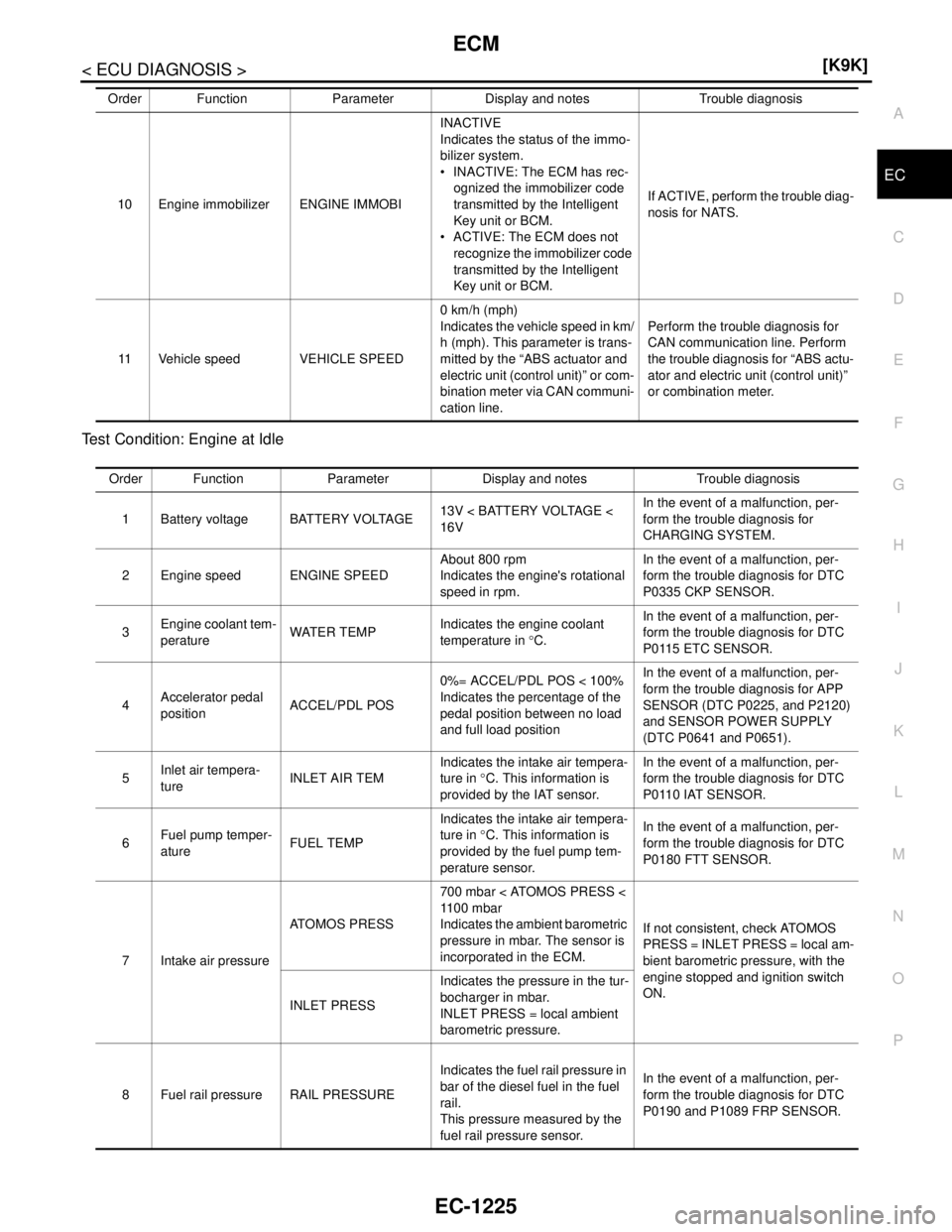
P O Test Condition: Engine at Idle
10 Engine immobilizer ENGINE IMMOBIINACTIVE
Indicates the status of the immo-
bilizer system.
INACTIVE: The ECM has rec-
ognized the immobilizer code
transmitted by the Intelligent
Key unit or BCM.
ACTIVE: The ECM does not
recognize the immobilizer code
transmitted by the Intelligent
Key unit or BCM.If ACTIVE, perform the trouble diag-
nosis for NATS.
11 Vehicle speed VEHICLE SPEED0 km/h (mph)
Indicates the vehicle speed in km/
h (mph). This parameter is trans-
mitted by the “ABS actuator and
electric unit (control unit)” or com-
bination meter via CAN communi-
cation line.Perform the trouble diagnosis for
CAN communication line. Perform
the trouble diagnosis for “ABS actu-
ator and electric unit (control unit)”
or combination meter. Order Function Parameter Display and notes Trouble diagnosis
Order Function Parameter Display and notes Trouble diagnosis
1 Battery voltage BATTERY VOLTAGE13V < BATTERY VOLTAGE <
16VIn the event of a malfunction, per-
form the trouble diagnosis for
CHARGING SYSTEM.
2 Engine speed ENGINE SPEEDAbout 800 rpm
Indicates the engine's rotational
speed in rpm.In the event of a malfunction, per-
form the trouble diagnosis for DTC
P0335 CKP SENSOR.
3Engine coolant tem-
peratureWATER TEMPIndicates the engine coolant
temperature in °C.In the event of a malfunction, per-
form the trouble diagnosis for DTC
P0115 ETC SENSOR.
4Accelerator pedal
positionACCEL/PDL POS0%= ACCEL/PDL POS < 100%
Indicates the percentage of the
pedal position between no load
and full load positionIn the event of a malfunction, per-
form the trouble diagnosis for APP
SENSOR (DTC P0225, and P2120)
and SENSOR POWER SUPPLY
(DTC P0641 and P0651).
5Inlet air tempera-
tureINLET AIR TEMIndicates the intake air tempera-
ture in °C. This information is
provided by the IAT sensor.In the event of a malfunction, per-
form the trouble diagnosis for DTC
P0110 IAT SENSOR.
6Fuel pump temper-
atureFUEL TEMPIndicates the intake air tempera-
ture in °C. This information is
provided by the fuel pump tem-
perature sensor.In the event of a malfunction, per-
form the trouble diagnosis for DTC
P0180 FTT SENSOR.
7 Intake air pressureATOMOS PRESS700 mbar < ATOMOS PRESS <
11 0 0 m b a r
Indicates the ambient barometric
pressure in mbar. The sensor is
incorporated in the ECM.If not consistent, check ATOMOS
PRESS = INLET PRESS = local am-
bient barometric pressure, with the
engine stopped and ignition switch
ON.
INLET PRESSIndicates the pressure in the tur-
bocharger in mbar.
INLET PRESS = local ambient
barometric pressure.
8 Fuel rail pressure RAIL PRESSUREIndicates the fuel rail pressure in
bar of the diesel fuel in the fuel
rail.
This pressure measured by the
fuel rail pressure sensor.In the event of a malfunction, per-
form the trouble diagnosis for DTC
P0190 and P1089 FRP SENSOR.
Page 2575 of 5883
EC-1226
< ECU DIAGNOSIS >[K9K]
ECM
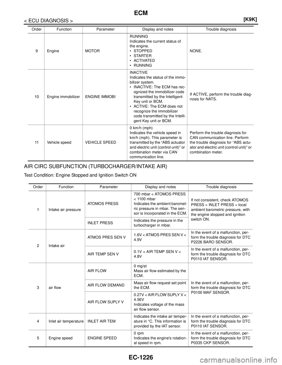
AIR CIRC SUBFUNCTION (TURBOCHARGER/INTAKE AIR)
Test Condition: Engine Stopped and Ignition Switch ON
9 Engine MOTORRUNNING
Indicates the current status of
the engine.
STOPPED
STARTER
A C T I VAT E D
RUNNINGNONE.
10 Engine immobilizer ENGINE IMMOBIINACTIVE
Indicates the status of the immo-
bilizer system.
INACTIVE: The ECM has rec-
ognized the immobilizer code
transmitted by the Intelligent
Key unit or BCM.
ACTIVE: The ECM does not
recognize the immobilizer
code transmitted by the Intelli-
gent Key unit or BCM.If ACTIVE, perform the trouble diag-
nosis for NATS.
11 Vehicle speed VEHICLE SPEED0 km/h (mph)
Indicates the vehicle speed in
km/h (mph). This parameter is
transmitted by the “ABS actuator
and electric unit (control unit)” or
combination meter via CAN
communication line.Perform the trouble diagnosis for
CAN communication line. Perform
the trouble diagnosis for “ABS actu-
ator and electric unit (control unit)” or
combination meter. Order Function Parameter Display and notes Trouble diagnosis
Order Function Parameter Display and notes Trouble diagnosis
1 Intake air pressureATOMOS PRESS700 mbar < ATOMOS PRESS
< 1100 mbar
Indicates the ambient baromet-
ric pressure in mbar. The sen-
sor is incorporated in the ECM.If not consistent, check ATOMOS
PRESS = INLET PRESS = local
ambient barometric pressure, with
the engine stopped and ignition
switch ON.
INLET PRESSIndicates the pressure in the
turbocharger in mbar.
2 Intake airATMOS PRES SEN V1.6V < ATMOS PRES SEN V <
4.9VIn the event of a malfunction, per-
form the trouble diagnosis for DTC
P2226 BARO SENSOR.
AIR TEMP SEN V0.1V < AIR TEMP SEN V <
4.8VIn the event of a malfunction, per-
form the trouble diagnosis for DTC
P0110 IAT SENSOR.
3air flowAIR FLOW0 mg/st
Mass air flow estimated by the
ECM.
In the event of a malfunction, per-
form the trouble diagnosis for DTC
P0100 MAF SENSOR. AIR FLOW DEMANDMass air flow request set point
the ECM.
AIR FLOW SUPLY V0.27V < AIR FLOW SUPLY V <
4.56V
Indicates voltage of the mass
air flow sensor.
4 Inlet air temperature INLET AIR TEMIndicates the intake air temper-
ature in °C. This information is
provided by the IAT sensor.In the event of a malfunction, per-
form the trouble diagnosis for DTC
P0110 IAT SENSOR.
5 Engine speed ENGINE SPEED0 rpm
Indicates the engine's rotation-
al speed in rpm.In the event of a malfunction, per-
form the trouble diagnosis for DTC
P0335 CKP SENSOR.
Page 2576 of 5883
ECM
EC-1227
< ECU DIAGNOSIS >[K9K]
C
D
E
F
G
H
I
J
K
L
MA
EC
N
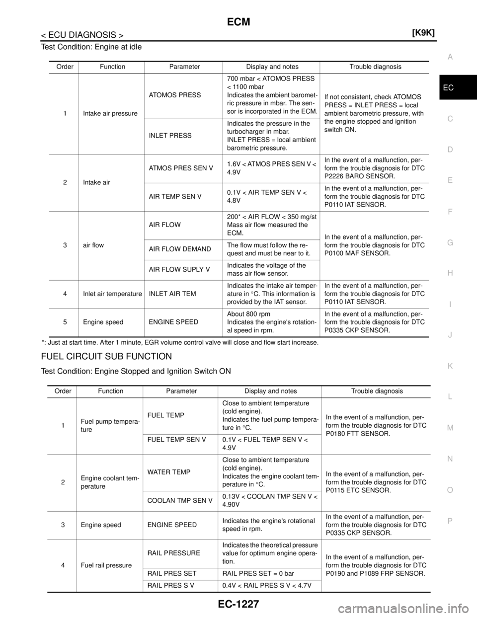
P O Test Condition: Engine at idle
*: Just at start time. After 1 minute, EGR volume control valve will close and flow start increase.
FUEL CIRCUIT SUB FUNCTION
Test Condition: Engine Stopped and Ignition Switch ON
Order Function Parameter Display and notes Trouble diagnosis
1 Intake air pressureATOMOS PRESS700 mbar < ATOMOS PRESS
< 1100 mbar
Indicates the ambient baromet-
ric pressure in mbar. The sen-
sor is incorporated in the ECM.If not consistent, check ATOMOS
PRESS = INLET PRESS = local
ambient barometric pressure, with
the engine stopped and ignition
switch ON.
INLET PRESSIndicates the pressure in the
turbocharger in mbar.
INLET PRESS = local ambient
barometric pressure.
2 Intake airATMOS PRES SEN V1.6V < ATMOS PRES SEN V <
4.9VIn the event of a malfunction, per-
form the trouble diagnosis for DTC
P2226 BARO SENSOR.
AIR TEMP SEN V0.1V < AIR TEMP SEN V <
4.8VIn the event of a malfunction, per-
form the trouble diagnosis for DTC
P0110 IAT SENSOR.
3air flowAIR FLOW200* < AIR FLOW < 350 mg/st
Mass air flow measured the
ECM.
In the event of a malfunction, per-
form the trouble diagnosis for DTC
P0100 MAF SENSOR. AIR FLOW DEMANDThe flow must follow the re-
quest and must be near to it.
AIR FLOW SUPLY VIndicates the voltage of the
mass air flow sensor.
4 Inlet air temperature INLET AIR TEMIndicates the intake air temper-
ature in °C. This information is
provided by the IAT sensor.In the event of a malfunction, per-
form the trouble diagnosis for DTC
P0110 IAT SENSOR.
5 Engine speed ENGINE SPEEDAbout 800 rpm
Indicates the engine's rotation-
al speed in rpm.In the event of a malfunction, per-
form the trouble diagnosis for DTC
P0335 CKP SENSOR.
Order Function Parameter Display and notes Trouble diagnosis
1Fuel pump tempera-
tureFUEL TEMPClose to ambient temperature
(cold engine).
Indicates the fuel pump tempera-
ture in °C.In the event of a malfunction, per-
form the trouble diagnosis for DTC
P0180 FTT SENSOR.
FUEL TEMP SEN V 0.1V < FUEL TEMP SEN V <
4.9V
2Engine coolant tem-
peratureWATER TEMPClose to ambient temperature
(cold engine).
Indicates the engine coolant tem-
perature in °C.In the event of a malfunction, per-
form the trouble diagnosis for DTC
P0115 ETC SENSOR.
COOLAN TMP SEN V0.13V < COOLAN TMP SEN V <
4.90V
3 Engine speed ENGINE SPEEDIndicates the engine's rotational
speed in rpm.In the event of a malfunction, per-
form the trouble diagnosis for DTC
P0335 CKP SENSOR.
4 Fuel rail pressureRAIL PRESSUREIndicates the theoretical pressure
value for optimum engine opera-
tion.In the event of a malfunction, per-
form the trouble diagnosis for DTC
P0190 and P1089 FRP SENSOR. RAIL PRES SET RAIL PRES SET = 0 bar
RAIL PRES S V 0.4V < RAIL PRES S V < 4.7V
Page 2577 of 5883
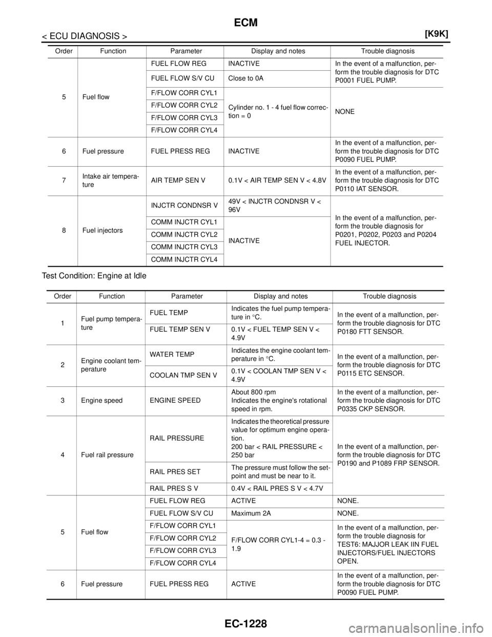
EC-1228
< ECU DIAGNOSIS >[K9K]
ECM
Test Condition: Engine at Idle
5 Fuel flowFUEL FLOW REG INACTIVE In the event of a malfunction, per-
form the trouble diagnosis for DTC
P0001 FUEL PUMP. FUEL FLOW S/V CU Close to 0A
F/FLOW CORR CYL1
Cylinder no. 1 - 4 fuel flow correc-
tion = 0NONE F/FLOW CORR CYL2
F/FLOW CORR CYL3
F/FLOW CORR CYL4
6 Fuel pressure FUEL PRESS REG INACTIVEIn the event of a malfunction, per-
form the trouble diagnosis for DTC
P0090 FUEL PUMP.
7Intake air tempera-
tureAIR TEMP SEN V 0.1V < AIR TEMP SEN V < 4.8VIn the event of a malfunction, per-
form the trouble diagnosis for DTC
P0110 IAT SENSOR.
8 Fuel injectorsINJCTR CONDNSR V49V < INJCTR CONDNSR V <
96V
In the event of a malfunction, per-
form the trouble diagnosis for
P0201, P0202, P0203 and P0204
FUEL INJECTOR. COMM INJCTR CYL1
INACTIVE COMM INJCTR CYL2
COMM INJCTR CYL3
COMM INJCTR CYL4 Order Function Parameter Display and notes Trouble diagnosis
Order Function Parameter Display and notes Trouble diagnosis
1Fuel pump tempera-
tureFUEL TEMPIndicates the fuel pump tempera-
ture in °C.In the event of a malfunction, per-
form the trouble diagnosis for DTC
P0180 FTT SENSOR. FUEL TEMP SEN V 0.1V < FUEL TEMP SEN V <
4.9V
2Engine coolant tem-
peratureWATER TEMPIndicates the engine coolant tem-
perature in °C.In the event of a malfunction, per-
form the trouble diagnosis for DTC
P0115 ETC SENSOR.
COOLAN TMP SEN V0.1V < COOLAN TMP SEN V <
4.9V
3 Engine speed ENGINE SPEEDAbout 800 rpm
Indicates the engine's rotational
speed in rpm.In the event of a malfunction, per-
form the trouble diagnosis for DTC
P0335 CKP SENSOR.
4 Fuel rail pressureRAIL PRESSUREIndicates the theoretical pressure
value for optimum engine opera-
tion.
200 bar < RAIL PRESSURE <
250 barIn the event of a malfunction, per-
form the trouble diagnosis for DTC
P0190 and P1089 FRP SENSOR.
RAIL PRES SETThe pressure must follow the set-
point and must be near to it.
RAIL PRES S V 0.4V < RAIL PRES S V < 4.7V
5 Fuel flowFUEL FLOW REG ACTIVE NONE.
FUEL FLOW S/V CU Maximum 2A NONE.
F/FLOW CORR CYL1
F/FLOW CORR CYL1-4 = 0.3 -
1.9In the event of a malfunction, per-
form the trouble diagnosis for
TEST6: MAJJOR LEAK IIN FUEL
INJECTORS/FUEL INJECTORS
OPEN. F/FLOW CORR CYL2
F/FLOW CORR CYL3
F/FLOW CORR CYL4
6 Fuel pressure FUEL PRESS REG ACTIVEIn the event of a malfunction, per-
form the trouble diagnosis for DTC
P0090 FUEL PUMP.
Page 2903 of 5883
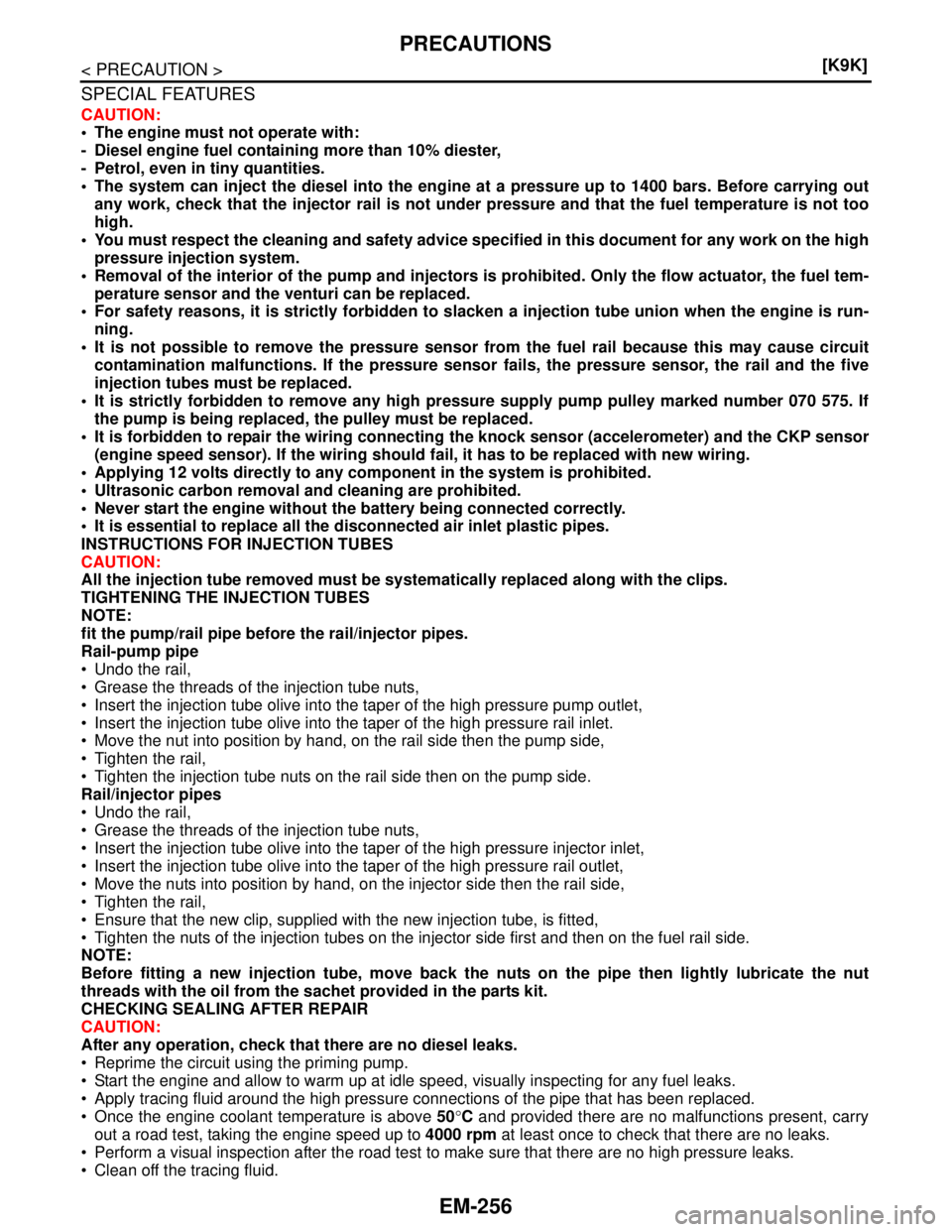
EM-256
< PRECAUTION >[K9K]
PRECAUTIONS
SPECIAL FEATURES
CAUTION:
The engine must not operate with:
- Diesel engine fuel containing more than 10% diester,
- Petrol, even in tiny quantities.
The system can inject the diesel into the engine at a pressure up to 1400 bars. Before carrying out
any work, check that the injector rail is not under pressure and that the fuel temperature is not too
high.
You must respect the cleaning and safety advice specified in this document for any work on the high
pressure injection system.
Removal of the interior of the pump and injectors is prohibited. Only the flow actuator, the fuel tem-
perature sensor and the venturi can be replaced.
For safety reasons, it is strictly forbidden to slacken a injection tube union when the engine is run-
ning.
It is not possible to remove the pressure sensor from the fuel rail because this may cause circuit
contamination malfunctions. If the pressure sensor fails, the pressure sensor, the rail and the five
injection tubes must be replaced.
It is strictly forbidden to remove any high pressure supply pump pulley marked number 070 575. If
the pump is being replaced, the pulley must be replaced.
It is forbidden to repair the wiring connecting the knock sensor (accelerometer) and the CKP sensor
(engine speed sensor). If the wiring should fail, it has to be replaced with new wiring.
Applying 12 volts directly to any component in the system is prohibited.
Ultrasonic carbon removal and cleaning are prohibited.
Never start the engine without the battery being connected correctly.
It is essential to replace all the disconnected air inlet plastic pipes.
INSTRUCTIONS FOR INJECTION TUBES
CAUTION:
All the injection tube removed must be systematically replaced along with the clips.
TIGHTENING THE INJECTION TUBES
NOTE:
fit the pump/rail pipe before the rail/injector pipes.
Rail-pump pipe
Undo the rail,
Grease the threads of the injection tube nuts,
Insert the injection tube olive into the taper of the high pressure pump outlet,
Insert the injection tube olive into the taper of the high pressure rail inlet.
Move the nut into position by hand, on the rail side then the pump side,
Tighten the rail,
Tighten the injection tube nuts on the rail side then on the pump side.
Rail/injector pipes
Undo the rail,
Grease the threads of the injection tube nuts,
Insert the injection tube olive into the taper of the high pressure injector inlet,
Insert the injection tube olive into the taper of the high pressure rail outlet,
Move the nuts into position by hand, on the injector side then the rail side,
Tighten the rail,
Ensure that the new clip, supplied with the new injection tube, is fitted,
Tighten the nuts of the injection tubes on the injector side first and then on the fuel rail side.
NOTE:
Before fitting a new injection tube, move back the nuts on the pipe then lightly lubricate the nut
threads with the oil from the sachet provided in the parts kit.
CHECKING SEALING AFTER REPAIR
CAUTION:
After any operation, check that there are no diesel leaks.
Reprime the circuit using the priming pump.
Start the engine and allow to warm up at idle speed, visually inspecting for any fuel leaks.
Apply tracing fluid around the high pressure connections of the pipe that has been replaced.
Once the engine coolant temperature is above 50°C and provided there are no malfunctions present, carry
out a road test, taking the engine speed up to 4000 rpm at least once to check that there are no leaks.
Perform a visual inspection after the road test to make sure that there are no high pressure leaks.
Clean off the tracing fluid.