exl NISSAN TIIDA 2007 Service Repair Manual
[x] Cancel search | Manufacturer: NISSAN, Model Year: 2007, Model line: TIIDA, Model: NISSAN TIIDA 2007Pages: 5883, PDF Size: 78.95 MB
Page 1 of 5883
MODEL C11 SERIES
2007 NISSAN EUROPE S.A.S.
All rights reserved. No part of this Electronic Service Manual may be reproduced or stored in a retrieval system, or transmitted in any form,
or by any means, electronic, mechanical, photocopying, recording or otherwise, without the prior written permission of Nissan Europe
S.A.S., Paris, France.
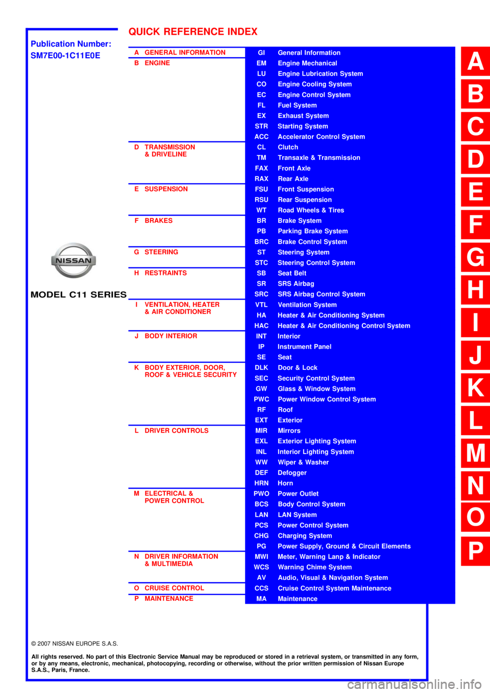
A GENERAL INFORMATION
B ENGINE
D TRANSMISSION& DRIVELINE
E SUSPENSION F BRAKES
G STEERING H RESTRAINTS
I VENTILATION, HEATER & AIR CONDITIONER
J BODY INTERIOR
K BODY EXTERIOR, DOOR, ROOF & VEHICLE SECURITY
L DRIVER CONTROLS
M ELECTRICAL & POWER CONTROL
N DRIVER INFORMATION & MULTIMEDIA
O CRUISE CONTROL P MAINTENANCEGI General Information
EM Engine Mechanical
LU Engine Lubrication System
CO Engine Cooling System
EC Engine Control System
FL Fuel System
EX Exhaust System
STR Starting System
ACC Accelerator Control System
CL Clutch
TM Transaxle & Transmission
FAX Front Axle
RAX Rear Axle
FSU Front Suspension
RSU Rear Suspension
WT Road Wheels & Tires
BR Brake System
PB Parking Brake System
BRC Brake Control System
ST Steering System
STC Steering Control System
SB Seat Belt
SR SRS Airbag
SRC SRS Airbag Control System
VTL Ventilation System
HA Heater & Air Conditioning System
HAC Heater & Air Conditioning Control System
INT Interior
IP Instrument Panel
SE Seat
DLK Door & Lock
SEC Security Control System
GW Glass & Window System
PWC Power Window Control System
RF Roof
EXT Exterior
MIR Mirrors
EXL Exterior Lighting System
INL Interior Lighting System
WW Wiper & Washer
DEF Defogger
HRN Horn
PWO Power Outlet
BCS Body Control System
LAN LAN System
PCS Power Control System
CHG Charging System
PG Power Supply, Ground & Circuit Elements
MWI Meter, Warning Lanp & Indicator
WCS Warning Chime System
AV Audio, Visual & Navigation System
CCS Cruise Control System Maintenance
MA Maintenance
QUICK REFERENCE INDEX
A
B
C
D
E
F
G
H
I
J
K
L
M
N
O
P
M
Publication Number:
SM7E00-1C11E0E
Page 142 of 5883
BCS
BODY CONTROL SYSTEM
BCS-7
< FUNCTION DIAGNOSIS >
C
D
E
F
G
H
I
J
K
L B A
O
P N
FUNCTION DIAGNOSIS
BODY CONTROL SYSTEM
System DescriptionINFOID:0000000001451453
OUTLINE
BCM (Body Control Module) controls the various electrical components. It inputs the information required to
the control from CAN communication and the signal received from each switch and sensor.
BCM has combination switch reading function for reading the operation status of combination switches (light,
turn signal, wiper and washer) in addition to a function for controlling the operation of various electrical com-
ponents. It also has the signal transmission function as the passed point of signal and the power consump-
tion control function that reduces the power consumption with the ignition switch OFF.
BCM is equipped with the diagnosis function that performs the diagnosis with CONSULT-III and various set-
tings.
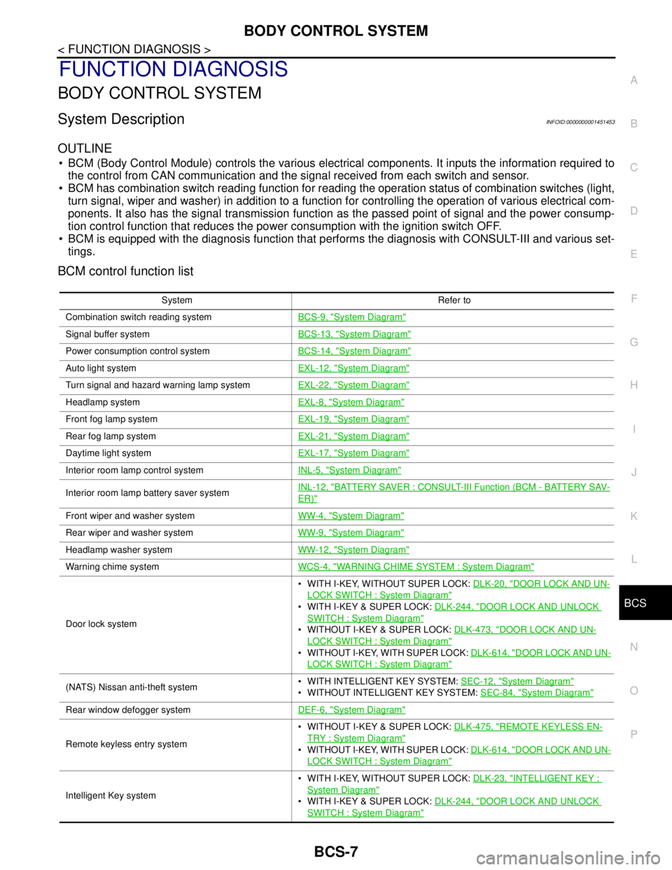
BCM control function list
System Refer to
Combination switch reading systemBCS-9, "
System Diagram"
Signal buffer systemBCS-13, "System Diagram"
Power consumption control systemBCS-14, "System Diagram"
Auto light systemEXL-12, "System Diagram"
Turn signal and hazard warning lamp systemEXL-22, "System Diagram"
Headlamp systemEXL-8, "System Diagram"
Front fog lamp systemEXL-19, "System Diagram"
Rear fog lamp systemEXL-21, "System Diagram"
Daytime light systemEXL-17, "System Diagram"
Interior room lamp control systemINL-5, "System Diagram"
Interior room lamp battery saver systemINL-12, "BATTERY SAVER : CONSULT-III Function (BCM - BATTERY SAV-
ER)"
Front wiper and washer systemWW-4, "System Diagram"
Rear wiper and washer systemWW-9, "System Diagram"
Headlamp washer systemWW-12, "System Diagram"
Warning chime systemWCS-4, "WARNING CHIME SYSTEM : System Diagram"
Door lock system WITH I-KEY, WITHOUT SUPER LOCK: DLK-20, "
DOOR LOCK AND UN-
LOCK SWITCH : System Diagram"
WITH I-KEY & SUPER LOCK: DLK-244, "DOOR LOCK AND UNLOCK
SWITCH : System Diagram"
WITHOUT I-KEY & SUPER LOCK: DLK-473, "DOOR LOCK AND UN-
LOCK SWITCH : System Diagram"
WITHOUT I-KEY, WITH SUPER LOCK: DLK-614, "DOOR LOCK AND UN-
LOCK SWITCH : System Diagram"
(NATS) Nissan anti-theft system WITH INTELLIGENT KEY SYSTEM: SEC-12, "System Diagram"
WITHOUT INTELLIGENT KEY SYSTEM: SEC-84, "System Diagram"
Rear window defogger systemDEF-6, "System Diagram"
Remote keyless entry system WITHOUT I-KEY & SUPER LOCK: DLK-475, "
REMOTE KEYLESS EN-
TRY : System Diagram"
WITHOUT I-KEY, WITH SUPER LOCK: DLK-614, "DOOR LOCK AND UN-
LOCK SWITCH : System Diagram"
Intelligent Key system WITH I-KEY, WITHOUT SUPER LOCK: DLK-23, "
INTELLIGENT KEY :
System Diagram"
WITH I-KEY & SUPER LOCK: DLK-244, "DOOR LOCK AND UNLOCK
SWITCH : System Diagram"
Page 167 of 5883
BCS-32
< COMPONENT DIAGNOSIS >
COMBINATION SWITCH INPUT CIRCUIT
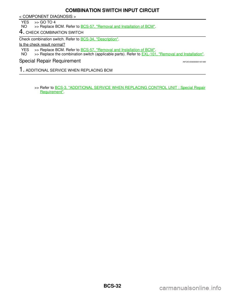
YES >> GO TO 4
NO >> Replace BCM. Refer to BCS-57, "
Removal and Installation of BCM".
4. CHECK COMBINATION SWITCH
Check combination switch. Refer to BCS-34, "
Description".
Is the check result normal?
YES >> Replace BCM. Refer to BCS-57, "Removal and Installation of BCM".
NO >> Replace the combination switch (applicable parts). Refer to EXL-101, "
Removal and Installation".
Special Repair RequirementINFOID:0000000001451490
1. ADDITIONAL SERVICE WHEN REPLACING BCM
>> Refer to BCS-3, "
ADDITIONAL SERVICE WHEN REPLACING CONTROL UNIT : Special Repair
Requirement".
Page 168 of 5883
BCS
COMBINATION SWITCH OUTPUT CIRCUIT
BCS-33
< COMPONENT DIAGNOSIS >
C
D
E
F
G
H
I
J
K
L B A
O
P N
COMBINATION SWITCH OUTPUT CIRCUIT
Diagnosis ProcedureINFOID:0000000001451491
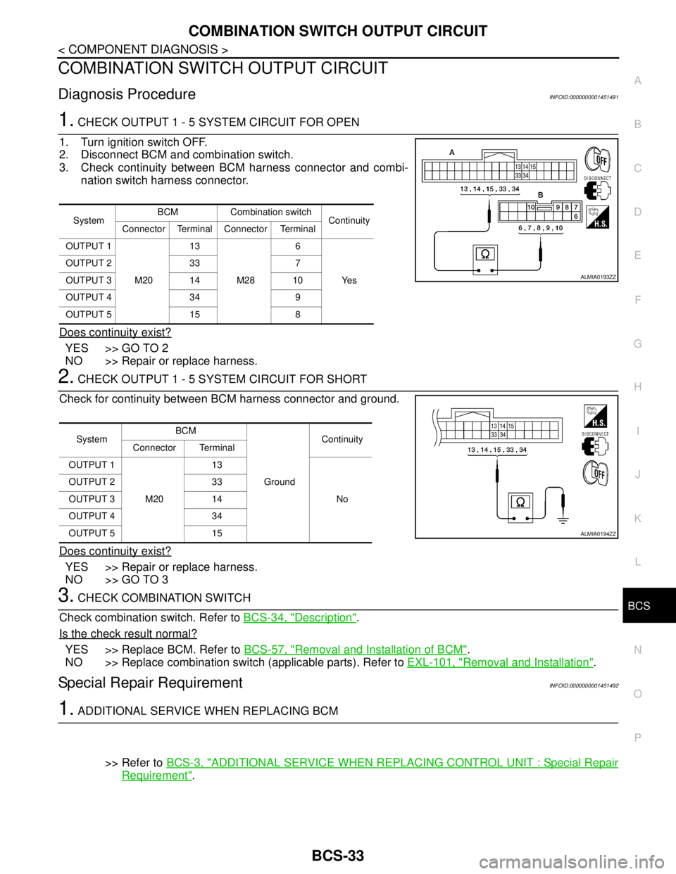
1. CHECK OUTPUT 1 - 5 SYSTEM CIRCUIT FOR OPEN
1. Turn ignition switch OFF.
2. Disconnect BCM and combination switch.
3. Check continuity between BCM harness connector and combi-
nation switch harness connector.
Does continuity exist?
YES >> GO TO 2
NO >> Repair or replace harness.
2. CHECK OUTPUT 1 - 5 SYSTEM CIRCUIT FOR SHORT
Check for continuity between BCM harness connector and ground.
Does continuity exist?
YES >> Repair or replace harness.
NO >> GO TO 3
3. CHECK COMBINATION SWITCH
Check combination switch. Refer to BCS-34, "
Description".
Is the check result normal?
YES >> Replace BCM. Refer to BCS-57, "Removal and Installation of BCM".
NO >> Replace combination switch (applicable parts). Refer to EXL-101, "
Removal and Installation".
Special Repair RequirementINFOID:0000000001451492
1. ADDITIONAL SERVICE WHEN REPLACING BCM
>> Refer to BCS-3, "
ADDITIONAL SERVICE WHEN REPLACING CONTROL UNIT : Special Repair
Requirement".
SystemBCM Combination switch
Continuity
Connector Terminal Connector Terminal
OUTPUT 1
M2013
M286
Ye s OUTPUT 2 33 7
OUTPUT 3 14 10
OUTPUT 4 34 9
OUTPUT 5 15 8
ALMIA0193ZZ
SystemBCM
GroundContinuity
Connector Terminal
OUTPUT 1
M2013
No OUTPUT 2 33
OUTPUT 3 14
OUTPUT 4 34
OUTPUT 5 15
ALMIA0194ZZ
Page 169 of 5883
BCS-34
< COMPONENT DIAGNOSIS >
COMBINATION SWITCH
COMBINATION SWITCH
DescriptionINFOID:0000000001451493
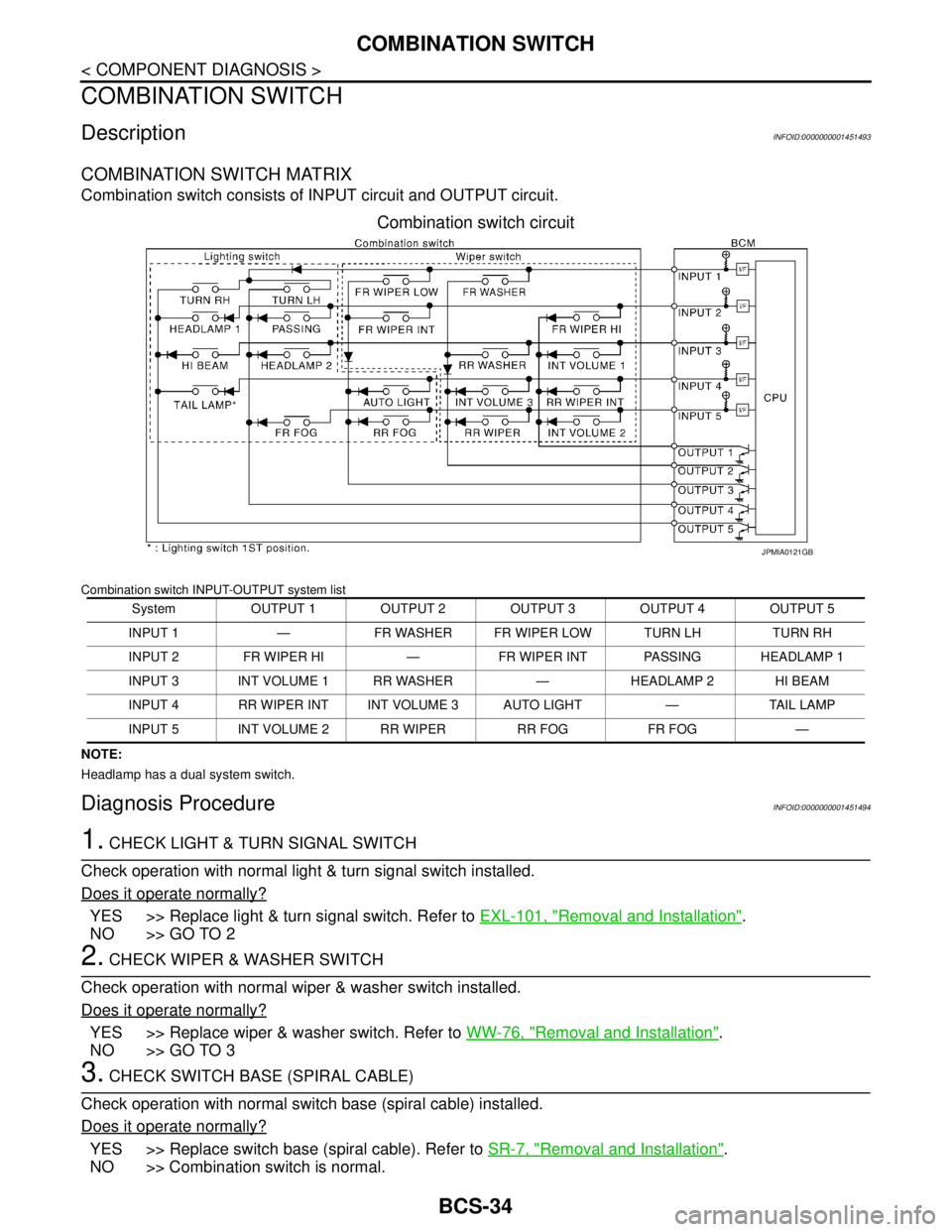
COMBINATION SWITCH MATRIX
Combination switch consists of INPUT circuit and OUTPUT circuit.
Combination switch circuit
Combination switch INPUT-OUTPUT system list
NOTE:
Headlamp has a dual system switch.
Diagnosis ProcedureINFOID:0000000001451494
1. CHECK LIGHT & TURN SIGNAL SWITCH
Check operation with normal light & turn signal switch installed.
Does it operate normally?
YES >> Replace light & turn signal switch. Refer to EXL-101, "Removal and Installation".
NO >> GO TO 2
2. CHECK WIPER & WASHER SWITCH
Check operation with normal wiper & washer switch installed.
Does it operate normally?
YES >> Replace wiper & washer switch. Refer to WW-76, "Removal and Installation".
NO >> GO TO 3
3. CHECK SWITCH BASE (SPIRAL CABLE)
Check operation with normal switch base (spiral cable) installed.
Does it operate normally?
YES >> Replace switch base (spiral cable). Refer to SR-7, "Removal and Installation".
NO >> Combination switch is normal.
System OUTPUT 1 OUTPUT 2 OUTPUT 3 OUTPUT 4 OUTPUT 5
INPUT 1 — FR WASHER FR WIPER LOW TURN LH TURN RH
INPUT 2 FR WIPER HI — FR WIPER INT PASSING HEADLAMP 1
INPUT 3 INT VOLUME 1 RR WASHER — HEADLAMP 2 HI BEAM
INPUT 4 RR WIPER INT INT VOLUME 3 AUTO LIGHT — TAIL LAMP
INPUT 5 INT VOLUME 2 RR WIPER RR FOG FR FOG —
JPMIA0121GB
Page 808 of 5883
![NISSAN TIIDA 2007 Service Repair Manual RADIATOR CORE SUPPORT
DLK-219
< REMOVAL AND INSTALLATION >[WITH I-KEY, WITHOUT SUPER LOCK]
C
D
E
F
G
H
I
J
L
MA
B
DLK
N
O
P
RADIATOR CORE SUPPORT
Removal and InstallationINFOID:0000000001315835
REMOVA NISSAN TIIDA 2007 Service Repair Manual RADIATOR CORE SUPPORT
DLK-219
< REMOVAL AND INSTALLATION >[WITH I-KEY, WITHOUT SUPER LOCK]
C
D
E
F
G
H
I
J
L
MA
B
DLK
N
O
P
RADIATOR CORE SUPPORT
Removal and InstallationINFOID:0000000001315835
REMOVA](/img/5/57395/w960_57395-807.png)
RADIATOR CORE SUPPORT
DLK-219
< REMOVAL AND INSTALLATION >[WITH I-KEY, WITHOUT SUPER LOCK]
C
D
E
F
G
H
I
J
L
MA
B
DLK
N
O
P
RADIATOR CORE SUPPORT
Removal and InstallationINFOID:0000000001315835
REMOVAL
Radiator Core Support Upper
1. Remove the air duct. Refer to EM-27, "Removal and Installation" (HR16DE), EM-154, "Removal and
Installation" (MR18DE), or EM-269, "Removal and Installation" (K9K).
2. Remove the headlamp (LH/RH). Refer to EXL-84, "
Removal and Installation" .
3. Remove the hood lock assembly, and remove hood lock cable. Refer to DLK-215
.
4. Remove the air guide and hood lock cable clip.
5. Remove the washer tank inlet. Refer to WW-64, "
Removal and Installation" .
6. Remove the radiator core support upper.
Radiator Core Support Lower
1. Remove the air duct. Refer to EM-27, "Removal and Installation" (HR16DE), EM-154, "Removal and
Installation" (MR18DE), or EM-269, "Removal and Installation" (K9K).
2. Remove the front bumper. Refer to EXT-13, "
Removal and Installation" .
3. Remove the headlamp (LH/RH). Refer to EXL-84, "
Removal and Installation" .
4. Remove the hood lock assembly, and remove hood lock cable. Refer to DLK-215
.
5. Remove the air guide and hood lock cable mounting clip.
6. Remove the front bumper reinforcement. Refer to EXT-13, "
Removal and Installation".
7. Remove the radiator core lower stay.
8. Remove the undercover.
PIIB6515E
1. Radiator core support upper 2. Radiator core support lower 3. Radiator core support lower stay
4. Radiator core support side stay 5. Air guide
24.5 N·m (2.5 kg-m, 18 ft-lb)
Page 810 of 5883
![NISSAN TIIDA 2007 Service Repair Manual FRONT FENDER
DLK-221
< REMOVAL AND INSTALLATION >[WITH I-KEY, WITHOUT SUPER LOCK]
C
D
E
F
G
H
I
J
L
MA
B
DLK
N
O
P
FRONT FENDER
Removal and InstallationINFOID:0000000001315836
REMOVAL
1. Remove the he NISSAN TIIDA 2007 Service Repair Manual FRONT FENDER
DLK-221
< REMOVAL AND INSTALLATION >[WITH I-KEY, WITHOUT SUPER LOCK]
C
D
E
F
G
H
I
J
L
MA
B
DLK
N
O
P
FRONT FENDER
Removal and InstallationINFOID:0000000001315836
REMOVAL
1. Remove the he](/img/5/57395/w960_57395-809.png)
FRONT FENDER
DLK-221
< REMOVAL AND INSTALLATION >[WITH I-KEY, WITHOUT SUPER LOCK]
C
D
E
F
G
H
I
J
L
MA
B
DLK
N
O
P
FRONT FENDER
Removal and InstallationINFOID:0000000001315836
REMOVAL
1. Remove the headlamp assemblies. Refer to EXL-84, "Removal and Installation".
2. Remove the cowl top cover (LH/RH). Refer to EXT-20, "
Removal and Installation".
3. Remove the front fender protector. Refer to DLK-221, "
Removal and Installation".
4. Remove the bolt and the front fender.
CAUTION:
While removing use a shop cloth to protect the vechicle body from damage.
INSTALLATION
Installation is in the reverse order of removal.
CAUTION:
After installing, apply touch-up paint onto the head of the front fender bolts.
After installing, check front fender adjustment. Refer to DLK-213, "
Fitting Adjustment" and DLK-222,
"Fitting Adjustment".
1. Front fender 2 Bolt (LH 7 bolts required) (RH 8 bolts
required)
LIIA2657E
Page 1037 of 5883
![NISSAN TIIDA 2007 Service Repair Manual DLK-448
< REMOVAL AND INSTALLATION >[WITH I-KEY & SUPER LOCK]
RADIATOR CORE SUPPORT
RADIATOR CORE SUPPORT
Removal and InstallationINFOID:0000000001732021
REMOVAL
Radiator Core Support Upper
1. Remove NISSAN TIIDA 2007 Service Repair Manual DLK-448
< REMOVAL AND INSTALLATION >[WITH I-KEY & SUPER LOCK]
RADIATOR CORE SUPPORT
RADIATOR CORE SUPPORT
Removal and InstallationINFOID:0000000001732021
REMOVAL
Radiator Core Support Upper
1. Remove](/img/5/57395/w960_57395-1036.png)
DLK-448
< REMOVAL AND INSTALLATION >[WITH I-KEY & SUPER LOCK]
RADIATOR CORE SUPPORT
RADIATOR CORE SUPPORT
Removal and InstallationINFOID:0000000001732021
REMOVAL
Radiator Core Support Upper
1. Remove the air duct. Refer to EM-27, "Removal and Installation" (HR16DE), EM-154, "Removal and
Installation" (MR18DE), or EM-269, "Removal and Installation" (K9K).
2. Remove the headlamp (LH/RH). Refer to EXL-84, "
Removal and Installation" .
3. Remove the hood lock assembly, and remove hood lock cable. Refer to DLK-444
.
4. Remove the air guide and hood lock cable clip.
5. Remove the washer tank inlet. Refer to WW-64, "
Removal and Installation" .
6. Remove the radiator core support upper.
Radiator Core Support Lower
1. Remove the air duct. Refer to EM-27, "Removal and Installation" (HR16DE), EM-154, "Removal and
Installation" (MR18DE), or EM-269, "Removal and Installation" (K9K).
2. Remove the front bumper. Refer to EXT-13, "
Removal and Installation" .
3. Remove the headlamp (LH/RH). Refer to EXL-84, "
Removal and Installation" .
4. Remove the hood lock assembly, and remove hood lock cable. Refer to DLK-444
.
5. Remove the air guide and hood lock cable mounting clip.
6. Remove the front bumper reinforcement. Refer to EXT-13, "
Removal and Installation".
7. Remove the radiator core lower stay.
8. Remove the undercover.
PIIB6515E
1. Radiator core support upper 2. Radiator core support lower 3. Radiator core support lower stay
4. Radiator core support side stay 5. Air guide
24.5 N·m (2.5 kg-m, 18 ft-lb)
Page 1039 of 5883
![NISSAN TIIDA 2007 Service Repair Manual DLK-450
< REMOVAL AND INSTALLATION >[WITH I-KEY & SUPER LOCK]
FRONT FENDER
FRONT FENDER
Removal and InstallationINFOID:0000000001732022
REMOVAL
1. Remove the headlamp assemblies. Refer to EXL-84, "Rem NISSAN TIIDA 2007 Service Repair Manual DLK-450
< REMOVAL AND INSTALLATION >[WITH I-KEY & SUPER LOCK]
FRONT FENDER
FRONT FENDER
Removal and InstallationINFOID:0000000001732022
REMOVAL
1. Remove the headlamp assemblies. Refer to EXL-84, "Rem](/img/5/57395/w960_57395-1038.png)
DLK-450
< REMOVAL AND INSTALLATION >[WITH I-KEY & SUPER LOCK]
FRONT FENDER
FRONT FENDER
Removal and InstallationINFOID:0000000001732022
REMOVAL
1. Remove the headlamp assemblies. Refer to EXL-84, "Removal and Installation".
2. Remove the cowl top cover (LH/RH). Refer to EXT-20, "
Removal and Installation".
3. Remove the front fender protector. Refer to DLK-450, "
Removal and Installation".
4. Remove the bolt and the front fender.
CAUTION:
While removing use a shop cloth to protect the vechicle body from damage.
INSTALLATION
Installation is in the reverse order of removal.
CAUTION:
After installing, apply touch-up paint onto the head of the front fender bolts.
After installing, check front fender adjustment. Refer to DLK-442, "
Fitting Adjustment" and DLK-451,
"Fitting Adjustment".
1. Front fender 2 Bolt (LH 7 bolts required) (RH 8 bolts
required)
LIIA2657E
Page 1178 of 5883
![NISSAN TIIDA 2007 Service Repair Manual RADIATOR CORE SUPPORT
DLK-589
< REMOVAL AND INSTALLATION >[WITHOUT I-KEY & SUPER LOCK]
C
D
E
F
G
H
I
J
L
MA
B
DLK
N
O
P
RADIATOR CORE SUPPORT
Removal and InstallationINFOID:0000000001732039
REMOVAL
Ra NISSAN TIIDA 2007 Service Repair Manual RADIATOR CORE SUPPORT
DLK-589
< REMOVAL AND INSTALLATION >[WITHOUT I-KEY & SUPER LOCK]
C
D
E
F
G
H
I
J
L
MA
B
DLK
N
O
P
RADIATOR CORE SUPPORT
Removal and InstallationINFOID:0000000001732039
REMOVAL
Ra](/img/5/57395/w960_57395-1177.png)
RADIATOR CORE SUPPORT
DLK-589
< REMOVAL AND INSTALLATION >[WITHOUT I-KEY & SUPER LOCK]
C
D
E
F
G
H
I
J
L
MA
B
DLK
N
O
P
RADIATOR CORE SUPPORT
Removal and InstallationINFOID:0000000001732039
REMOVAL
Radiator Core Support Upper
1. Remove the air duct. Refer to EM-27, "Removal and Installation" (HR16DE), EM-154, "Removal and
Installation" (MR18DE), or EM-269, "Removal and Installation" (K9K).
2. Remove the headlamp (LH/RH). Refer to EXL-84, "
Removal and Installation" .
3. Remove the hood lock assembly, and remove hood lock cable. Refer to DLK-585
.
4. Remove the air guide and hood lock cable clip.
5. Remove the washer tank inlet. Refer to WW-64, "
Removal and Installation" .
6. Remove the radiator core support upper.
Radiator Core Support Lower
1. Remove the air duct. Refer to EM-27, "Removal and Installation" (HR16DE), EM-154, "Removal and
Installation" (MR18DE), or EM-269, "Removal and Installation" (K9K).
2. Remove the front bumper. Refer to EXT-13, "
Removal and Installation" .
3. Remove the headlamp (LH/RH). Refer to EXL-84, "
Removal and Installation" .
4. Remove the hood lock assembly, and remove hood lock cable. Refer to DLK-585
.
5. Remove the air guide and hood lock cable mounting clip.
6. Remove the front bumper reinforcement. Refer to EXT-13, "
Removal and Installation".
7. Remove the radiator core lower stay.
8. Remove the undercover.
PIIB6515E
1. Radiator core support upper 2. Radiator core support lower 3. Radiator core support lower stay
4. Radiator core support side stay 5. Air guide
24.5 N·m (2.5 kg-m, 18 ft-lb)