fuse box NISSAN TIIDA 2007 Service Repair Manual
[x] Cancel search | Manufacturer: NISSAN, Model Year: 2007, Model line: TIIDA, Model: NISSAN TIIDA 2007Pages: 5883, PDF Size: 78.95 MB
Page 3047 of 5883

EXL-46
< COMPONENT DIAGNOSIS >
PARKING LAMP CIRCUIT
PARKING LAMP CIRCUIT
WITH DAYTIME LIGHT SYSTEM
WITH DAYTIME LIGHT SYSTEM : DescriptionINFOID:0000000001523268
The IPDM E/R (Intelligent Power Distribution Module Engine Room) controls the daytime light relay based on
inputs from the BCM via the CAN communication lines. When the daytime light relay is energized power flows
to the front and rear combination lamps and the license plate lamps.
WITH DAYTIME LIGHT SYSTEM : Component Function CheckINFOID:0000000001523269
1.CHECK PARKING LAMP OPERATION
CONSULT-III
1. Select "TAIL LAMP" of IPDM E/R active test item.
2. With test items operating, check that the parking lamps are turned ON.
Is the parking lamp turned ON?
YES >> Parking lamp circuit is normal.
NO >> Refer to EXL-46, "
WITH DAYTIME LIGHT SYSTEM : Diagnosis Procedure".
WITH DAYTIME LIGHT SYSTEM : Diagnosis ProcedureINFOID:0000000001523270
1.CHECK PARKING LAMP FUSE
1. Turn the ignition switch OFF.
2. Check that the following fuse is not open.
Is the fuse open?
YES >> Repair the harness and replace the fuse.
NO >> GO TO 2
2.CHECK DAYTIME LIGHT RELAY OUTPUT (VOLTAGE)
CONSULT-III
1. Turn the ignition switch OFF.
2. Disconnect the front or rear combination lamp connectors.
3. Turn the ignition switch ON.
4. Select "TAIL LAMP" of IPDM E/R active test item.
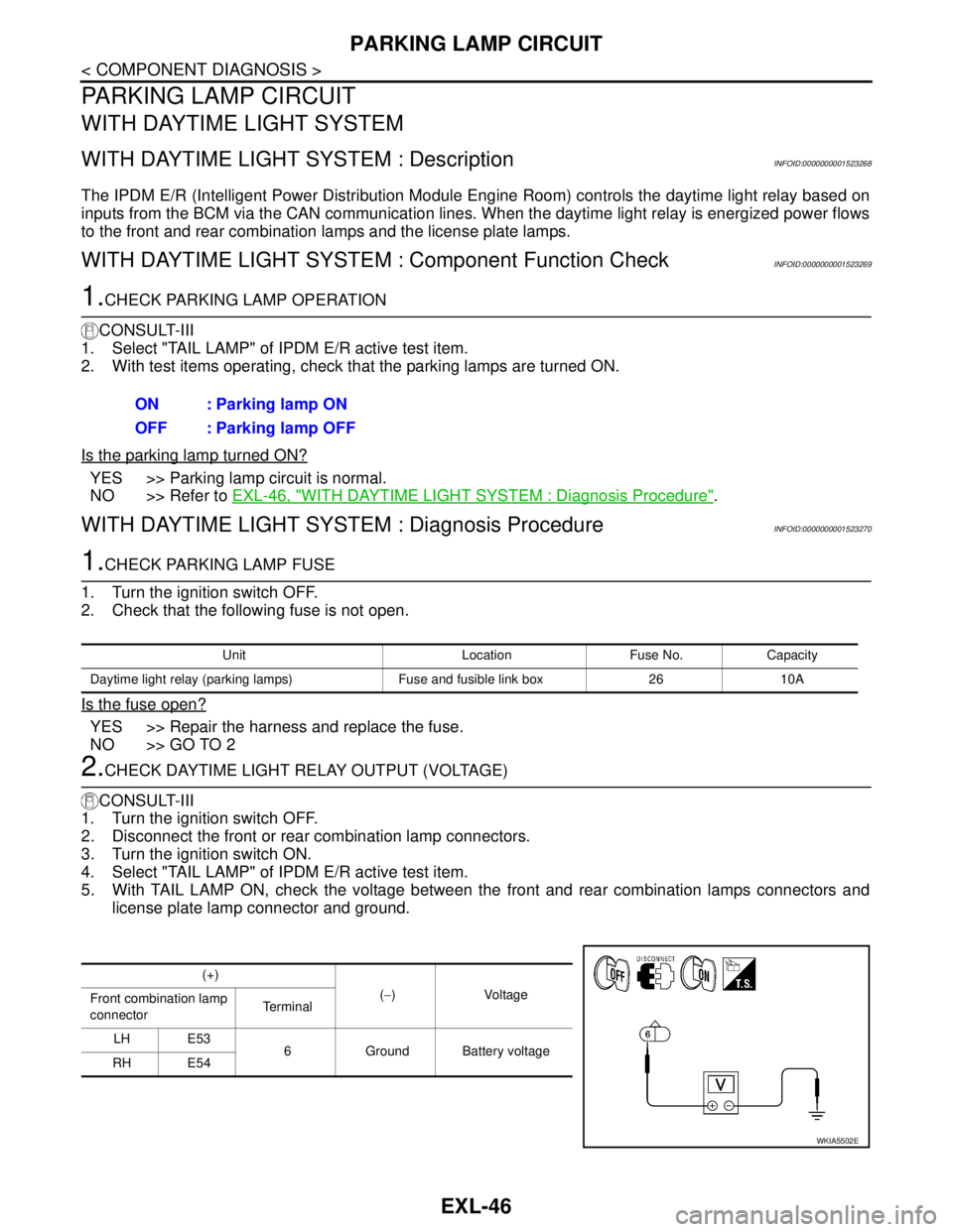
5. With TAIL LAMP ON, check the voltage between the front and rear combination lamps connectors and
license plate lamp connector and ground.ON : Parking lamp ON
OFF : Parking lamp OFF
Unit Location Fuse No. Capacity
Daytime light relay (parking lamps) Fuse and fusible link box 26 10A
(+)
(−)Voltage
Front combination lamp
connectorTe r m i n a l
LH E53
6 Ground Battery voltage
RH E54
WKIA5502E
Page 3206 of 5883

GI-12
< HOW TO USE THIS MANUAL >
HOW TO USE THIS MANUAL
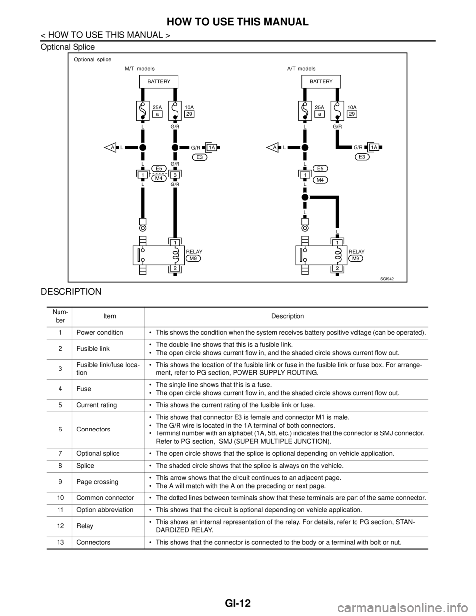
Optional Splice
DESCRIPTION
SGI942
Num-
berItem Description
1 Power condition This shows the condition when the system receives battery positive voltage (can be operated).
2Fusible link The double line shows that this is a fusible link.
The open circle shows current flow in, and the shaded circle shows current flow out.
3Fusible link/fuse loca-
tion This shows the location of the fusible link or fuse in the fusible link or fuse box. For arrange-
ment, refer to PG section, POWER SUPPLY ROUTING.
4Fuse The single line shows that this is a fuse.
The open circle shows current flow in, and the shaded circle shows current flow out.
5 Current rating This shows the current rating of the fusible link or fuse.
6 Connectors This shows that connector E3 is female and connector M1 is male.
The G/R wire is located in the 1A terminal of both connectors.
Terminal number with an alphabet (1A, 5B, etc.) indicates that the connector is SMJ connector.
Refer to PG section, SMJ (SUPER MULTIPLE JUNCTION).
7 Optional splice The open circle shows that the splice is optional depending on vehicle application.
8 Splice The shaded circle shows that the splice is always on the vehicle.
9 Page crossing This arrow shows that the circuit continues to an adjacent page.
The A will match with the A on the preceding or next page.
10 Common connector The dotted lines between terminals show that these terminals are part of the same connector.
11 Option abbreviation This shows that the circuit is optional depending on vehicle application.
12 Relay This shows an internal representation of the relay. For details, refer to PG section, STAN-
DARDIZED RELAY.
13 Connectors This shows that the connector is connected to the body or a terminal with bolt or nut.
Page 3207 of 5883

HOW TO USE THIS MANUAL
GI-13
< HOW TO USE THIS MANUAL >
C
D
E
F
G
H
I
J
K
L
MB
GI
N
O
P
Harness Indication
14 Wire color This shows a code for the color of the wire.
B = Black
W = White
R = Red
G = Green
L = Blue
Y = Yellow
LG = Light GreenBR = Brown
OR or O = Orange
P = Pink
PU or V (Violet) = Purple
GY or GR = Gray
SB = Sky Blue
CH = Dark Brown
DG = Dark Green
When the wire color is striped, the base color is given first, followed by the stripe color as shown
below:
Example: L/W = Blue with White Stripe
15 Option description This shows a description of the option abbreviation used on the page.
16 Switch This shows that continuity exists between terminals 1 and 2 when the switch is in the A posi-
tion. Continuity exists between terminals 1 and 3 when the switch is in the B position.
17 Assembly parts Connector terminal in component shows that it is a harness incorporated assembly.
18 Cell code This identifies each page of the wiring diagram by section, system and wiring diagram page
number.
19 Current flow arrow Arrow indicates electric current flow, especially where the direction of standard flow (vertically
downward or horizontally from left to right) is difficult to follow.
A double arrow “ ” shows that current can flow in either direction depending on circuit
operation.
20 System branch This shows that the system branches to another system identified by cell code (section and
system).
21 Page crossing This arrow shows that the circuit continues to another page identified by cell code.
The C will match with the C on another page within the system other than the next or preceding
pages.
22 Shielded line The line enclosed by broken line circle shows shield wire.
23Component box in
wave line This shows that another part of the component is also shown on another page (indicated by
wave line) within the system.
24 Component name This shows the name of a component.
25 Connector number This shows the connector number.
The letter shows which harness the connector is located in.
Example: M: main harness. For detail and to locate the connector, refer to PG section "Main
Harness", “Harness Layout”. A coordinate grid is included for complex harnesses to aid in lo-
cating connectors.
26 Ground (GND) The line spliced and grounded under wire color shows that ground line is spliced at the ground-
ed connector.
27 Ground (GND) This shows the ground connection. For detailed ground distribution information, refer to
"Ground Distribution" in PG section.
28 Connector views This area shows the connector faces of the components in the wiring diagram on the page.
29 Common component Connectors enclosed in broken line show that these connectors belong to the same compo-
nent.
30 Connector color This shows a code for the color of the connector. For code meaning, refer to wire color codes,
Number 14 of this chart.
31Fusible link and fuse
box This shows the arrangement of fusible link(s) and fuse(s), used for connector views of "POW-
ER SUPPLY ROUTING" in PG section.
The open square shows current flow in, and the shaded square shows current flow out.
32 Reference area This shows that more information on the Super Multiple Junction (SMJ) and Joint Connectors
(J/C) exists on the PG section. Refer to "Reference Area" for details. Num-
berItem Description
Page 3477 of 5883
![NISSAN TIIDA 2007 Service Repair Manual HAC-144
< COMPONENT DIAGNOSIS >[AUTO AIR CONDITIONER (W/O NAVI)]
PTC HEATER CONTROL SYSTEM
The ambient sensor is attached on the radiator core support upper. It
detects ambient temperature and convert NISSAN TIIDA 2007 Service Repair Manual HAC-144
< COMPONENT DIAGNOSIS >[AUTO AIR CONDITIONER (W/O NAVI)]
PTC HEATER CONTROL SYSTEM
The ambient sensor is attached on the radiator core support upper. It
detects ambient temperature and convert](/img/5/57395/w960_57395-3476.png)
HAC-144
< COMPONENT DIAGNOSIS >[AUTO AIR CONDITIONER (W/O NAVI)]
PTC HEATER CONTROL SYSTEM
The ambient sensor is attached on the radiator core support upper. It
detects ambient temperature and converts it into a resistance value
which is then input into the front air control.
PTC HEATER (300 WATT) : PTC Heater (300 Watt) Diagnosis ProcedureINFOID:0000000001682708
DIAGNOSTIC PROCEDURE FOR PTC SYSTEM
SYMPTOM: PTC heater system operation is malfunction.
1.CHECK POWER SUPPLY FOR PTC RELAY-1
1. Turn ignition switch ON.
2. Check voltage between PTC relay-1 harness connector E61 ter-
minals 2, 3, and ground.
Is the inspection result normal
YES >> GO TO 2.
NO >> Check power supply circuit and 10A fuse (No. 2) and 40A fusible link (No. I), located in the fuse
and fusible link box.
If fuses are OK, check harness for open circuit. Repair or replace if necessary.
If fuses are NG, replace fuse and check harness for short circuit. Repair or replace if necessary.
2.CHECK PTC RELAY-1
1. Turn ignition switch OFF.
2. Check PTC relay-1. Refer to HAC-151, "
PTC HEATER (300 WATT) : PTC Heater (300 Watt) Component
Inspection".
Is the inspection result normal
YES >> GO TO 3.
NO >> Replace PTC relay-1. Refer to XX.
3.CHECK PTC RELAY-1 OUTPUT CIRCUIT
1. Disconnect ambient sensor, PTC heater and water temperature
sensor connectors.
2. Turn temperature control dial clockwise until full hot position.
3. Turn mode control dial to foot position.
4. Start the engine.
5. Turn blower control dial to maximum speed.
6. Check continuity between PTC relay-1 harness connector E61
terminal 1 and ground.
Is the inspection result normal
YES >> GO TO 5.
AWIIA0600ZZ
Te r m i n a l s
Voltag e
(Approx.)
(+) (−)
Connector Terminal
Ground Battery voltage
PTC relay-1: E612
3
SJIA0913E
Connector Terminal
GroundContinuity
PTC relay-1: E61 1 Yes
AWIIA0455ZZ
Page 3591 of 5883
![NISSAN TIIDA 2007 Service Repair Manual HAC-258
< COMPONENT DIAGNOSIS >[AUTO AIR CONDITIONER (W/NAVI)]
PTC HEATER CONTROL SYSTEM
The ambient sensor is attached on the radiator core support upper. It
detects ambient temperature and converts NISSAN TIIDA 2007 Service Repair Manual HAC-258
< COMPONENT DIAGNOSIS >[AUTO AIR CONDITIONER (W/NAVI)]
PTC HEATER CONTROL SYSTEM
The ambient sensor is attached on the radiator core support upper. It
detects ambient temperature and converts](/img/5/57395/w960_57395-3590.png)
HAC-258
< COMPONENT DIAGNOSIS >[AUTO AIR CONDITIONER (W/NAVI)]
PTC HEATER CONTROL SYSTEM
The ambient sensor is attached on the radiator core support upper. It
detects ambient temperature and converts it into a resistance value
which is then input into the front air control.
PTC HEATER (300 WATT) : PTC Heater (300 Watt) Diagnosis ProcedureINFOID:0000000001548107
DIAGNOSTIC PROCEDURE FOR PTC SYSTEM
SYMPTOM: PTC heater system operation is malfunction.
1.CHECK POWER SUPPLY FOR PTC RELAY-1
1. Turn ignition switch ON.
2. Check voltage between PTC relay-1 harness connector E61 ter-
minals 2, 3, and ground.
Is the inspection result normal
YES >> GO TO 2.
NO >> Check power supply circuit and 10A fuse (No. 2) and 40A fusible link (No. I), located in the fuse
and fusible link box.
If fuses are OK, check harness for open circuit. Repair or replace if necessary.
If fuses are NG, replace fuse and check harness for short circuit. Repair or replace if necessary.
2.CHECK PTC RELAY-1
1. Turn ignition switch OFF.
2. Check PTC relay-1. Refer to HAC-265, "
PTC HEATER (300 WATT) : PTC Heater (300 Watt) Component
Inspection".
Is the inspection result normal
YES >> GO TO 3.
NO >> Replace PTC relay-1. Refer to XX.
3.CHECK PTC RELAY-1 OUTPUT CIRCUIT
1. Disconnect ambient sensor, PTC heater and water temperature
sensor connectors.
2. Turn temperature control dial clockwise until full hot position.
3. Turn mode control dial to foot position.
4. Start the engine.
5. Turn blower control dial to maximum speed.
6. Check continuity between PTC relay-1 harness connector E61
terminal 1 and ground.
Is the inspection result normal
YES >> GO TO 5.
AWIIA0600ZZ
Te r m i n a l s
Voltag e
(Approx.)
(+) (−)
Connector Terminal
Ground Battery voltage
PTC relay-1: E612
3
SJIA0913E
Connector Terminal
GroundContinuity
PTC relay-1: E61 1 Yes
AWIIA0455ZZ
Page 3726 of 5883

INSTRUMENT PANEL ASSEMBLY
IP-11
< SERVICE INFORMATION >
C
D
E
F
G
H
I
K
L
MA
B
IP
N
O
P
NOTE:
The LHD model shown, RHD similar.
Removal and InstallationINFOID:0000000001523318
NOTE:
The LHD model shown, RHD model similar.
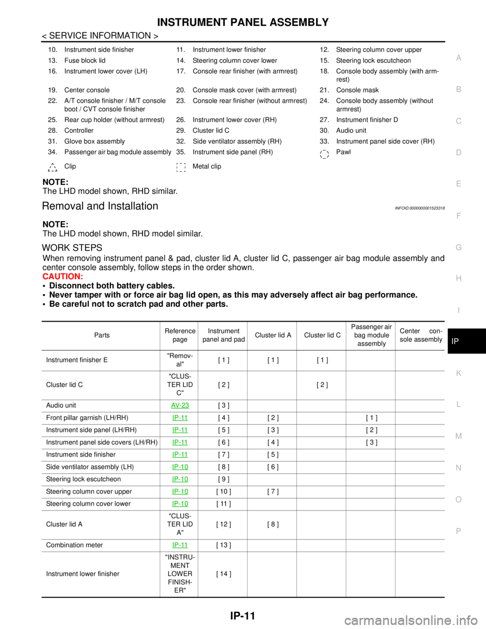
WORK STEPS
When removing instrument panel & pad, cluster lid A, cluster lid C, passenger air bag module assembly and
center console assembly, follow steps in the order shown.
CAUTION:
Disconnect both battery cables.
Never tamper with or force air bag lid open, as this may adversely affect air bag performance.
Be careful not to scratch pad and other parts.
10. Instrument side finisher 11. Instrument lower finisher 12. Steering column cover upper
13. Fuse block lid 14. Steering column cover lower 15. Steering lock escutcheon
16. Instrument lower cover (LH) 17. Console rear finisher (with armrest) 18. Console body assembly (with arm-
rest)
19. Center console 20. Console mask cover (with armrest) 21. Console mask
22. A/T console finisher / M/T console
boot / CVT console finisher23. Console rear finisher (without armrest) 24. Console body assembly (without
armrest)
25. Rear cup holder (without armrest) 26. Instrument lower cover (RH) 27. Instrument finisher D
28. Controller 29. Cluster lid C 30. Audio unit
31. Glove box assembly 32. Side ventilator assembly (RH) 33. Instrument panel side cover (RH)
34. Passenger air bag module assembly 35. Instrument side panel (RH) Pawl
Clip Metal clip
PartsReference
pageInstrument
panel and padCluster lid A Cluster lid C Passenger air
bag module
assemblyCenter con-
sole assembly
Instrument finisher E"Remov-
al"[ 1 ] [ 1 ] [ 1 ]
Cluster lid C"CLUS-
TER LID
C"[ 2 ] [ 2 ]
Audio unitAV- 2 3
[ 3 ]
Front pillar garnish (LH/RH)IP-11
[ 4 ] [ 2 ] [ 1 ]
Instrument side panel (LH/RH)IP-11
[ 5 ] [ 3 ] [ 2 ]
Instrument panel side covers (LH/RH)IP-11
[ 6 ] [ 4 ] [ 3 ]
Instrument side finisherIP-11
[ 7 ] [ 5 ]
Side ventilator assembly (LH)IP-10
[ 8 ] [ 6 ]
Steering lock escutcheonIP-10
[ 9 ]
Steering column cover upperIP-10
[ 10 ] [ 7 ]
Steering column cover lowerIP-10
[ 11 ]
Cluster lid A"CLUS-
TER LID
A"[ 12 ] [ 8 ]
Combination meterIP-11
[ 13 ]
Instrument lower finisher"INSTRU-
MENT
LOWER
FINISH-
ER"[ 14 ]
Page 3727 of 5883
![NISSAN TIIDA 2007 Service Repair Manual IP-12
< SERVICE INFORMATION >
INSTRUMENT PANEL ASSEMBLY
[ ]: Number indicates step in removal procedures.
INSTRUMENT PANEL ASSEMBLY
Removal
1. Pull instrument finisher E backward by approximately 30
d NISSAN TIIDA 2007 Service Repair Manual IP-12
< SERVICE INFORMATION >
INSTRUMENT PANEL ASSEMBLY
[ ]: Number indicates step in removal procedures.
INSTRUMENT PANEL ASSEMBLY
Removal
1. Pull instrument finisher E backward by approximately 30
d](/img/5/57395/w960_57395-3726.png)
IP-12
< SERVICE INFORMATION >
INSTRUMENT PANEL ASSEMBLY
[ ]: Number indicates step in removal procedures.
INSTRUMENT PANEL ASSEMBLY
Removal
1. Pull instrument finisher E backward by approximately 30
degrees while disengaging the instrument finisher E metal clips
and pawl.
Glove box assembly"GLOVE
BOX AS-
SEMBLY"[ 15 ]
Side ventilator assembly (RH)IP-10
[ 16 ] [ 4 ]
Passenger air bag module assemblySR-9
[ 17 ] [ 5 ]
Instrument upper maskIP-10
[ 18 ]
Instrument finisher DIP-10
[ 19 ]
Controller TM-674
[ 20 ]
Instrument upper panel assembly IP-11
[ 21 ]
Console mask"Remov-
al"[ 22 ] [ 1 ]
CVT, A/T console finisherIP-23
[ 23 ] [ 2 ]
M/T console bootIP-23
[ 23 ] [ 2 ]
Console rear finisherIP-23
[ 24 ] [ 3 ]
Console mask cover (with arm rest)IP-23
[ 25 ] [ 4 ]
Rear cup holder (without arm rest)IP-23
[ 25 ] [ 4 ]
Console body assemblyIP-23
[ 26 ] [ 5 ]
Instrument lower cover (LH/RH)"INSTRU-
MENT
LOWER
FINISH-
ER"[ 27 ] [ 6 ]
Center console assembly"CEN-
TER
CON-
SOLE AS-
SEMBLY"[ 28 ] [ 7 ]
Fuse block lidIP-10
[ 29 ]
Lighting and turn signal switchEXL-101
[ 30 ]
Wiper & washer switchWW-76
[ 31 ]
Instrument panel & padIP-10
[ 32 ] PartsReference
pageInstrument
panel and padCluster lid A Cluster lid C Passenger air
bag module
assemblyCenter con-
sole assembly
WIIA1224E
Page 3730 of 5883

INSTRUMENT PANEL ASSEMBLY
IP-15
< SERVICE INFORMATION >
C
D
E
F
G
H
I
K
L
MA
B
IP
N
O
P
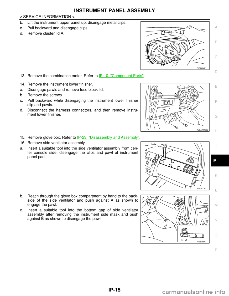
b. Lift the instrument upper panel up, disengage metal clips.
c. Pull backward and disengage clips.
d. Remove cluster lid A.
13. Remove the combination meter. Refer to IP-10, "
Component Parts".
14. Remove the instrument lower finisher.
a. Disengage pawls and remove fuse block lid.
b. Remove the screws.
c. Pull backward while disengaging the instrument lower finisher
clip and pawls.
d. Disconnect the harness connectors, and then remove instru-
ment lower finisher.
15. Remove glove box. Refer to IP-23, "
Disassembly and Assembly".
16. Remove side ventilator assembly.
a. Insert a suitable tool into the side ventilator assembly from cen-
ter console side, disengage the clips and pawl of instrument
panel pad.
b. Reach through the glove box compartment by hand to the back-
side of the side ventilator and push against A as shown to
engage the pawl.
c. Insert a suitable tool into the bottom gap of side ventilator
assembly after removing the instrument side mask and push
against B as shown to disengage the pawl.
PIIB2880E
ALJIA0096ZZ
PIIB3977E
PIIB6385E
Page 4884 of 5883
![NISSAN TIIDA 2007 Service Repair Manual STC-10
< COMPONENT DIAGNOSIS >[EPS]
C1601 BATTERY POWER SUPPLY
NG >> Check the following. If any items are damaged, repair or replace damaged parts.
60 A fusible link (letter m, located in the fuse NISSAN TIIDA 2007 Service Repair Manual STC-10
< COMPONENT DIAGNOSIS >[EPS]
C1601 BATTERY POWER SUPPLY
NG >> Check the following. If any items are damaged, repair or replace damaged parts.
60 A fusible link (letter m, located in the fuse](/img/5/57395/w960_57395-4883.png)
STC-10
< COMPONENT DIAGNOSIS >[EPS]
C1601 BATTERY POWER SUPPLY
NG >> Check the following. If any items are damaged, repair or replace damaged parts.
60 A fusible link (letter m, located in the fuse and fusible link box).
10 A fuse [No. 2, located in the fuse block (J/B)].
Harness for short or open between battery and EPS control unit harness connector M54 termi-
nal 17.
Harness for short or open between ignition switch and EPS control unit harness connector M53
terminal 10.
2.CHECK EPS CONTROL UNIT GROUND CIRCUIT
1. Turn ignition switch OFF.
2. Disconnect EPS control unit harness connector.
3. Check continuity between EPS control unit harness connector
M54 terminal 18 and ground.
Also check harness for short to power.
4. Connect EPS control unit harness connector.
OK or NG
OK >> GO TO 3.
NG >> Repair open circuit, short to ground or short to power in
harness or connectors.
3.CHECK DTC
1. Start engine.
Does EPS warning lamp turn OFF?
YES >>INSPECTION END
NO >> Perform self-diagnosis, repair or replace damaged parts. Refer to STC-7, "
CONSULT-III Function
(EPS)".
Special Repair Requirement (Models with ESP)INFOID:0000000001716734
1.ADJUSTMENT OF STEERING ANGLE SENSOR NEUTRAL POSITION
Always perform the neutral position adjustment for the steering angle sensor, when replacing the EPS control
unit. Refer to BRC-90, "
ADJUSTMENT OF STEERING ANGLE SENSOR NEUTRAL POSITION : Descrip-
tion".
>> END
Connector Terminal Continuity
M54 18 Yes
AWGIA0029ZZ
Page 4905 of 5883
![NISSAN TIIDA 2007 Service Repair Manual EPS WARNING LAMP DOES NOT TURN OFF
STC-31
< SYMPTOM DIAGNOSIS >[EPS]
C
D
E
F
H
I
J
K
L
MA
B
STC
N
O
P
EPS WARNING LAMP DOES NOT TURN OFF
Diagnosis ProcedureINFOID:0000000001697734
SYMPTOM:
EPS warnin NISSAN TIIDA 2007 Service Repair Manual EPS WARNING LAMP DOES NOT TURN OFF
STC-31
< SYMPTOM DIAGNOSIS >[EPS]
C
D
E
F
H
I
J
K
L
MA
B
STC
N
O
P
EPS WARNING LAMP DOES NOT TURN OFF
Diagnosis ProcedureINFOID:0000000001697734
SYMPTOM:
EPS warnin](/img/5/57395/w960_57395-4904.png)
EPS WARNING LAMP DOES NOT TURN OFF
STC-31
< SYMPTOM DIAGNOSIS >[EPS]
C
D
E
F
H
I
J
K
L
MA
B
STC
N
O
P
EPS WARNING LAMP DOES NOT TURN OFF
Diagnosis ProcedureINFOID:0000000001697734
SYMPTOM:
EPS warning lamp does not turn OFF for several seconds after starting the engine.
DIAGNOSTIC PROCEDURE
1.CHECK SELF-DIAGNOSTIC RESULTS
Perform self-diagnosis. Refer to STC-7, "
CONSULT-III Function (EPS)".
Is any malfunction detected by self-diagnosis?
YES >> Check the malfunctioning system.
NO >> GO TO 2.
2.CHECK EPS CONTROL UNIT POWER SUPPLY CIRCUIT
1. Turn ignition switch OFF.
2. Disconnect EPS control unit harness connector.
3. Turn ignition switch ON. (Do not start engine.)
4. Check voltage between EPS control unit harness connector
M53 (A) terminal 10 and M54 (B) terminal 17 and ground.
5. Turn ignition switch OFF.
6. Check voltage between EPS control unit harness connector
M53 (A) terminal 10 and M54 (B) terminal 17 and ground.
7. Connect EPS control unit harness connector.
OK or NG
OK >> GO TO 3.
NG >> Check the following. If any items are damaged, repair
or replace damaged parts.
60 A fusible link (letter m , located in the fuse and fusible link box).
10 A fuse [No. 2, located in the fuse block (J/B)].
Harness for short or open between battery and EPS control unit harness connector M54 termi-
nal 17.
Harness for short or open between ignition switch and EPS control unit harness connector M53
terminal 10.
3.CHECK EPS CONTROL UNIT GROUND CIRCUIT
1. Turn ignition switch OFF.
2. Disconnect EPS control unit harness connector.
Connector Terminal Voltage
(A) M53 10 – Ground Battery voltage
(B) M54 17 – Ground Battery voltage
AWGIA0031ZZ
Connector Terminal Voltage
(A) M53 10 – Ground Approx. 0 V
(B) M54 17 – Ground Battery voltage
AWGIA0028ZZ