low beam NISSAN TIIDA 2007 Service Repair Manual
[x] Cancel search | Manufacturer: NISSAN, Model Year: 2007, Model line: TIIDA, Model: NISSAN TIIDA 2007Pages: 5883, PDF Size: 78.95 MB
Page 144 of 5883
BCS
COMBINATION SWITCH READING SYSTEM
BCS-9
< FUNCTION DIAGNOSIS >
C
D
E
F
G
H
I
J
K
L B A
O
P N
COMBINATION SWITCH READING SYSTEM
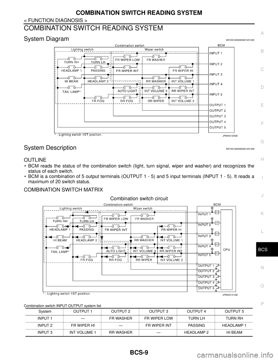
System DiagramINFOID:0000000001451455
System DescriptionINFOID:0000000001451456
OUTLINE
BCM reads the status of the combination switch (light, turn signal, wiper and washer) and recognizes the
status of each switch.
BCM is a combination of 5 output terminals (OUTPUT 1 - 5) and 5 input terminals (INPUT 1 - 5). It reads a
maximum of 20 switch status.
COMBINATION SWITCH MATRIX
Combination switch circuit
Combination switch INPUT-OUTPUT system list
JPMIA0120GB
System OUTPUT 1 OUTPUT 2 OUTPUT 3 OUTPUT 4 OUTPUT 5
INPUT 1 — FR WASHER FR WIPER LOW TURN LH TURN RH
INPUT 2 FR WIPER HI — FR WIPER INT PASSING HEADLAMP 1
INPUT 3 INT VOLUME 1 RR WASHER — HEADLAMP 2 HI BEAM
JPMIA0121GB
Page 156 of 5883

BCS
DIAGNOSIS SYSTEM (BCM)
BCS-21
< FUNCTION DIAGNOSIS >
C
D
E
F
G
H
I
J
K
L B A
O
P N
ACTIVE TEST
WIPER
WIPER : CONSULT-III Function (BCM - WIPER)INFOID:0000000001451471
WORK SUPPORT
HI BEAM SW [ON/OFF]
Each switch status that BCM judges from the combination switch reading function H/L SW POS [ON/OFF]
LIGHT SW 1ST [ON/OFF]
PASSING SW [ON/OFF]
AUTO LIGHT SW [ON/OFF]
FR FOG SW [ON/OFF]
RR FOG SW [ON/OFF]
DOOR SW-DR [ON/OFF] The switch status input from front door switch (driver side)
ENGINE STATUS The engine status received from ECM with CAN communication
LIT-SEN FAIL [OK/NOTOK] The sensor status received from light & rain sensor with serial link
The serial link condition that BCM judges
AUT LIGHT SYS [ON/OFF] Auto light system status that BCM judges from the vehicle conditionMonitor item
[Unit]Description
Test item Operation Description
TAIL LAMPONTransmits the position light request signal to IPDM E/R with CAN com-
munication to turn the tail lamp ON.
OFF Stops the tail lamp request signal transmission.
HEAD LAMPHITransmits the high beam request signal with CAN communication to turn
the headlamp (HI).
LOTransmits the low beam request signal with CAN communication to turn
the headlamp (LO).
OFF Stops the high & low beam request signal transmission.
FR FOG LAMPONTransmits the front fog lights request signal to IPDM E/R with CAN com-
munication to turn the front fog lamp ON.
OFF Stops the front fog lights request signal transmission.
RR FOG LAMPON Outputs the voltage to turn the rear fog lamp ON.
Transmits the rear fog lamp status signal to the combination meter with
CAN communication to turn the rear fog lamp indicator lamp ON.
OFF Stops the voltage to turn the rear fog lamp OFF.
Stops the rear fog lamp status signal transmission.
DAYTIME RUNNING LIGHTONTransmits the day time running light request signal to IPDM E/R with
CAN communication to turn the each lamps ON.
OFF Stops the day time running light request signal transmission.
Work ItemSetting
ItemDescription
WIPER SPEED
SETTINGON
1With vehicle speed
(Front wiper intermittent time linked with the vehicle speed and wiper intermittent dial position)
OFFWithout vehicle speed
(Front wiper intermittent time linked with the wiper intermittent dial position)
RR WIP RVRS
SETON
2Change ON/OFF mode setting or rear wiper operation when gear is shifted to reverse
OFF
Page 159 of 5883

BCS-24
< FUNCTION DIAGNOSIS >
DIAGNOSIS SYSTEM (BCM)
COMB SW
COMB SW : CONSULT-III Function (BCM - COMB SW)INFOID:0000000001451475
DATA MONITOR
IMMU
IMMU : CONSULT-III Function (BCM - IMMU)INFOID:0000000001451476
DATA MONITOR
DOOR SW-RL [ON/OFF] Indicates condition of front door switch LH.
BACK DOOR SW [ON/OFF] Indicates condition of back door switch.Monitor Item
[Unit]Condition
Monitor Item
[Unit]Description
TURN SIGNAL R
[OFF/ON]Displays the status of the TURN RH switch in combination switch judged by BCM with the combination switch
reading function.
TURN SIGNAL L
[OFF/ON]Displays the status of the TURN LH switch in combination switch judged by BCM with the combination switch
reading function.
HI BEAM SW
[OFF/ON]Displays the status of the HI BEAM switch in combination switch judged by BCM with the combination switch
reading function.
H/L SW POS
[OFF/ON]Displays the status of the HEADLAMP switch in combination switch judged by BCM with the combination
switch reading function.
LIGHT SW 1ST
[OFF/ON]Displays the status of the HEADLAMP switch in combination switch judged by BCM with the combination
switch reading function.
PASSING SW
[OFF/ON]Displays the status of the PASSING switch in combination switch judged by BCM with the combination switch
reading function.
AUTO LIGHT SW
[OFF/ON]Displays the status of the AUTO LIGHT switch in combination switch judged by BCM with the combination
switch reading function.
FR FOG SW
[OFF/ON]Displays the status of the FR FOG switch in combination switch judged by BCM with the combination switch
reading function.
RR FOG SW
[OFF/ON]Displays the status of the RR FOG switch in combination switch judged by BCM with the combination switch
reading function.
FR WIPER HI
[OFF/ON]Displays the status of the FR WIPER HI switch in combination switch judged by BCM with the combination
switch reading function.
FR WIPER LOW
[OFF/ON]Displays the status of the FR WIPER LOW switch in combination switch judged by BCM with the combination
switch reading function.
FR WIPER INT
[OFF/ON]Displays the status of the FR WIPER INT switch in combination switch judged by BCM with the combination
switch reading function.
FR WASHER SW
[OFF/ON]Displays the status of the FR WASHER switch in combination switch judged by BCM with the combination
switch reading function.
INT VOLUME
[1 - 7]Displays the status of wiper intermittent dial position judged by BCM with the combination switch reading
function.
RR WIPER ON
[OFF/ON]Displays the status of the RR WIPER switch in combination switch judged by BCM with the combination
switch reading function.
RR WIPER INT
[OFF/ON]Displays the status of the RR WIPER INT switch in combination switch judged by BCM with the combination
switch reading function.
RR WASHER SW
[OFF/ON]Displays the status of the RR WASHER switch in combination switch judged by BCM with the combination
switch reading function.
Page 169 of 5883
BCS-34
< COMPONENT DIAGNOSIS >
COMBINATION SWITCH
COMBINATION SWITCH
DescriptionINFOID:0000000001451493
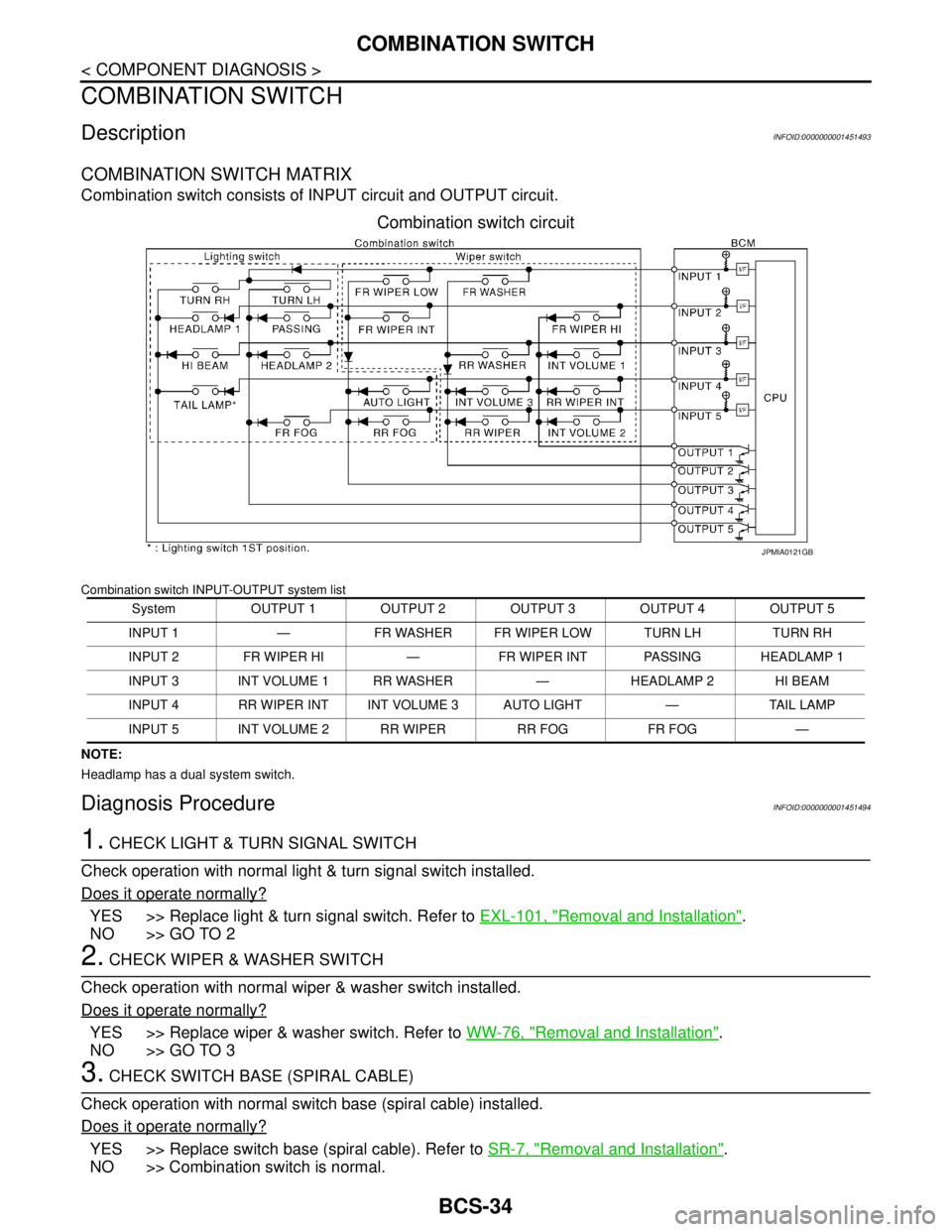
COMBINATION SWITCH MATRIX
Combination switch consists of INPUT circuit and OUTPUT circuit.
Combination switch circuit
Combination switch INPUT-OUTPUT system list
NOTE:
Headlamp has a dual system switch.
Diagnosis ProcedureINFOID:0000000001451494
1. CHECK LIGHT & TURN SIGNAL SWITCH
Check operation with normal light & turn signal switch installed.
Does it operate normally?
YES >> Replace light & turn signal switch. Refer to EXL-101, "Removal and Installation".
NO >> GO TO 2
2. CHECK WIPER & WASHER SWITCH
Check operation with normal wiper & washer switch installed.
Does it operate normally?
YES >> Replace wiper & washer switch. Refer to WW-76, "Removal and Installation".
NO >> GO TO 3
3. CHECK SWITCH BASE (SPIRAL CABLE)
Check operation with normal switch base (spiral cable) installed.
Does it operate normally?
YES >> Replace switch base (spiral cable). Refer to SR-7, "Removal and Installation".
NO >> Combination switch is normal.
System OUTPUT 1 OUTPUT 2 OUTPUT 3 OUTPUT 4 OUTPUT 5
INPUT 1 — FR WASHER FR WIPER LOW TURN LH TURN RH
INPUT 2 FR WIPER HI — FR WIPER INT PASSING HEADLAMP 1
INPUT 3 INT VOLUME 1 RR WASHER — HEADLAMP 2 HI BEAM
INPUT 4 RR WIPER INT INT VOLUME 3 AUTO LIGHT — TAIL LAMP
INPUT 5 INT VOLUME 2 RR WIPER RR FOG FR FOG —
JPMIA0121GB
Page 171 of 5883

BCS-36
< ECU DIAGNOSIS >
BCM (BODY CONTROL MODULE)
ENGINE RPM
NOTE:
Diesel engine models
onlyEngine runningApproximately the same as tachom-
eter reading
ENGINE RUNEngine stopped OFF
Engine running ON
ENGINE STATUS
NOTE:
Diesel engine models
onlyEngine stopped STOP
While the engine stalls STALL
Engine running RUN
At engine cranking CRA
FA N O N S I GFan switch OFF OFF
Fan switch ON ON
FR FOG SWFront fog lamp switch OFF OFF
Front fog lamp switch ON ON
FR WASHER SWFront washer switch OFF OFF
Front washer switch ON ON
FR WIPER LOWFront wiper switch OFF OFF
Front wiper switch LO ON
FR WIPER HIFront wiper switch OFF OFF
Front wiper switch HI ON
FR WIPER INTFront wiper switch OFF OFF
Front wiper switch INT ON
FR WIPER STOPAny position other than front wiper stop position OFF
Front wiper stop position ON
HAZARD SWWhen hazard switch is not pressed OFF
When hazard switch is pressed ON
LIGHT SW 1STLighting switch OFF OFF
Lighting switch 1st ON
H/L SW POSHeadlamp switch OFF OFF
Headlamp switch 1st ON
HI BEAM SWHigh beam switch OFF OFF
High beam switch HI ON
HOOD SWClose the hood
NOTE:
Vehicles without theft warning system are OFF-fixedOFF
Open the hood ON
H/L WASH SWNOTE:
The item is indicated, but not monitoredOFF
IGN ON SWIgnition switch OFF or ACC OFF
Ignition switch ON ON
IGN SW CANIgnition switch OFF or ACC OFF
Ignition switch ON ON
INT VOLUME Wiper intermittent dial is in a dial position 1 - 7 1 - 7
I-KEY LOCK
1LOCK button of Intelligent Key is not pressed OFF
LOCK button of Intelligent Key is pressed ON Monitor Item Condition Value/Status
Page 190 of 5883
BCS
COMBINATION SWITCH SYSTEM SYMPTOMS
BCS-55
< SYMPTOM DIAGNOSIS >
C
D
E
F
G
H
I
J
K
L B A
O
P N
SYMPTOM DIAGNOSIS
COMBINATION SWITCH SYSTEM SYMPTOMS
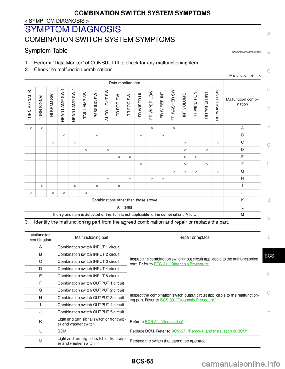
Symptom TableINFOID:0000000001451500
1. Perform “Data Monitor” of CONSULT-III to check for any malfunctioning item.
2. Check the malfunction combinations.
Malfunction item: ×
3. Identify the malfunctioning part from the agreed combination and repair or replace the part.
Data monitor item
Malfunction combi-
nation
TURN SIGNAL R
TURN SIGNAL L
HI BEAM SW
HEAD LAMP SW 1
HEAD LAMP SW 2
TAIL LAMP SW
PASSING SW
AUTO LIGHT SW
FR FOG SW
RR FOG SW
FR WIPER HI
FR WIPER LOW
FR WIPER INT
FR WASHER SW
INT VOLUME
RR WIPER ON
RR WIPER INT
RR WASHER SW
×× × ×A
×× ××B
×× × ×C
×× ××D
×× ××E
×××F
××× ×G
××××H
××××I
××××J
Combinations other than those above K
All Items L
If only one item is detected or the item is not applicable to the combinations A to L M
Malfunction
combinationMalfunctioning part Repair or replace
A Combination switch INPUT 1 circuit
Inspect the combination switch input circuit applicable to the malfunctioning
part. Refer to BCS-31, "
Diagnosis Procedure". B Combination switch INPUT 2 circuit
C Combination switch INPUT 3 circuit
D Combination switch INPUT 4 circuit
E Combination switch INPUT 5 circuit
F Combination switch OUTPUT 1 circuit
Inspect the combination switch output circuit applicable to the malfunction-
ing part. Refer to BCS-33, "
Diagnosis Procedure". G Combination switch OUTPUT 2 circuit
H Combination switch OUTPUT 3 circuit
I Combination switch OUTPUT 4 circuit
J Combination switch OUTPUT 5 circuit
KLight and turn signal switch or front wip-
er and washer switchRefer to BCS-34, "
Description".
L BCM Replace BCM. Refer to BCS-57, "
Removal and Installation of BCM".
MLight and turn signal switch or front wip-
er and washer switchReplace the switch that cannot be operated.
Page 3009 of 5883
EXL-8
< FUNCTION DIAGNOSIS >
HEADLAMP (HALOGEN)
FUNCTION DIAGNOSIS
HEADLAMP (HALOGEN)
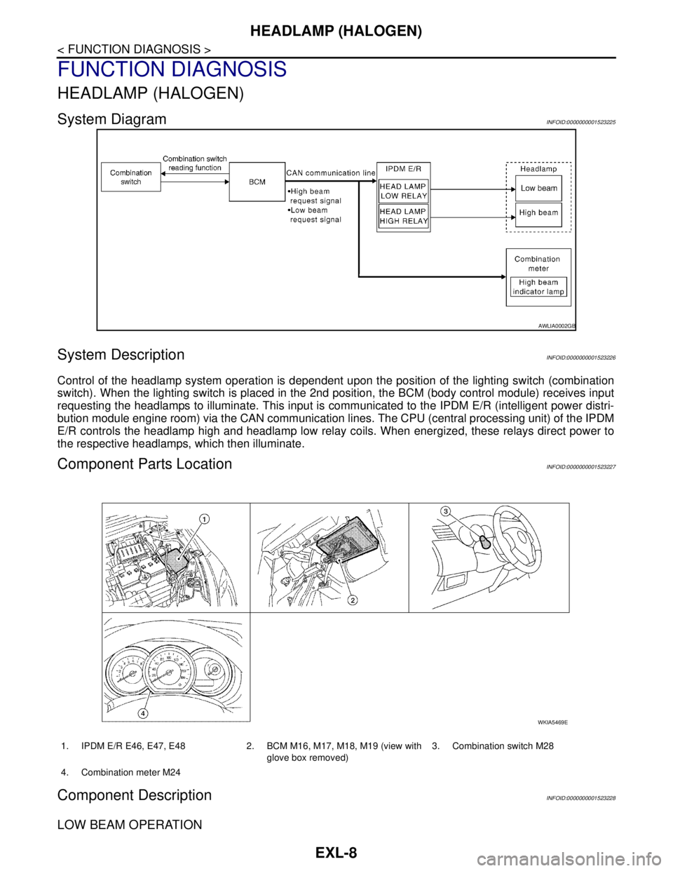
System DiagramINFOID:0000000001523225
System DescriptionINFOID:0000000001523226
Control of the headlamp system operation is dependent upon the position of the lighting switch (combination
switch). When the lighting switch is placed in the 2nd position, the BCM (body control module) receives input
requesting the headlamps to illuminate. This input is communicated to the IPDM E/R (intelligent power distri-
bution module engine room) via the CAN communication lines. The CPU (central processing unit) of the IPDM
E/R controls the headlamp high and headlamp low relay coils. When energized, these relays direct power to
the respective headlamps, which then illuminate.
Component Parts LocationINFOID:0000000001523227
Component DescriptionINFOID:0000000001523228
LOW BEAM OPERATION
AWLIA0002GB
1. IPDM E/R E46, E47, E48 2. BCM M16, M17, M18, M19 (view with
glove box removed)3. Combination switch M28
4. Combination meter M24
WKIA5469E
Page 3010 of 5883
HEADLAMP (HALOGEN)
EXL-9
< FUNCTION DIAGNOSIS >
C
D
E
F
G
H
I
J
K
MA
B
EXL
N
O
P
When the lighting switch is in 2nd position, the BCM receives input requesting the headlamps to illuminate.
This input is communicated to the IPDM E/R via the CAN communication lines. The CPU of the IPDM E/R
controls the headlamp low relay coil which supplies power to the low beam headlamps.
HIGH BEAM OPERATION/FLASH-TO-PASS OPERATION
With the lighting switch in the 2nd position and placed in HIGH position, the BCM receives input requesting the
headlamp high beams to illuminate. The flash to pass feature can be used any time and also sends a signal to
the BCM. This input is communicated to the IPDM E/R via the CAN communication lines. The CPU of the
combination meter controls the ON/OFF status off the HIGH BEAM indicator. The CPU of the IPDM E/R con-
trols the headlamp high relay coil which supplies power to the high beam headlamps.
The combination meter receives a high beam request signal (ON) via the CAN communication lines and turns
the high beam indicator lamp ON.
COMBINATION SWITCH READING FUNCTION
Refer to XX-XX, "*****".
Page 3011 of 5883
EXL-10
< FUNCTION DIAGNOSIS >
HEADLAMP (XENON)
HEADLAMP (XENON)
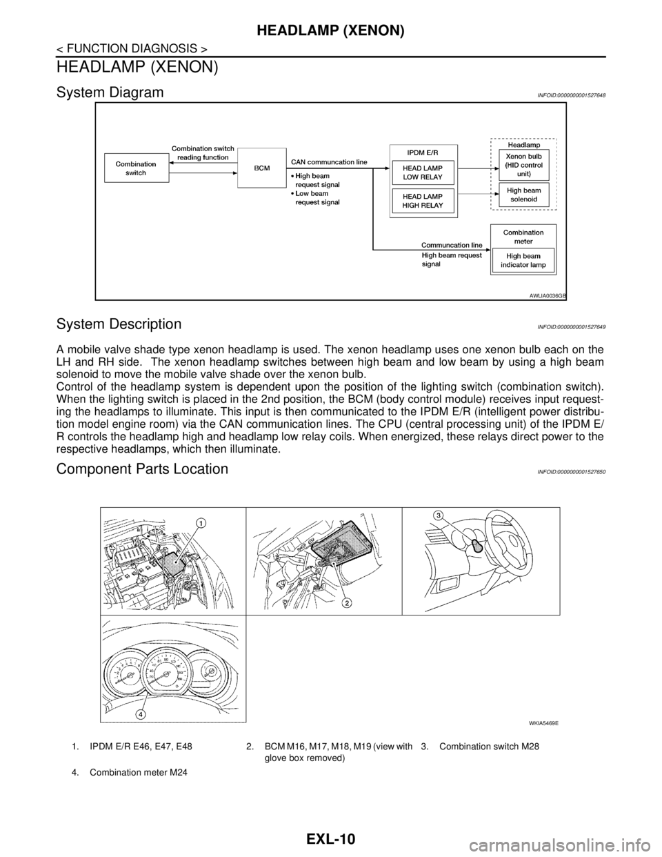
System DiagramINFOID:0000000001527648
System DescriptionINFOID:0000000001527649
A mobile valve shade type xenon headlamp is used. The xenon headlamp uses one xenon bulb each on the
LH and RH side. The xenon headlamp switches between high beam and low beam by using a high beam
solenoid to move the mobile valve shade over the xenon bulb.
Control of the headlamp system is dependent upon the position of the lighting switch (combination switch).
When the lighting switch is placed in the 2nd position, the BCM (body control module) receives input request-
ing the headlamps to illuminate. This input is then communicated to the IPDM E/R (intelligent power distribu-
tion model engine room) via the CAN communication lines. The CPU (central processing unit) of the IPDM E/
R controls the headlamp high and headlamp low relay coils. When energized, these relays direct power to the
respective headlamps, which then illuminate.
Component Parts LocationINFOID:0000000001527650
AWLIA0036GB
1. IPDM E/R E46, E47, E48 2. BCM M16, M17, M18, M19 (view with
glove box removed)3. Combination switch M28
4. Combination meter M24
WKIA5469E
Page 3012 of 5883
HEADLAMP (XENON)
EXL-11
< FUNCTION DIAGNOSIS >
C
D
E
F
G
H
I
J
K
MA
B
EXL
N
O
P
Component DescriptionINFOID:0000000001527651
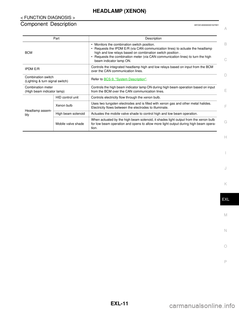
Part Description
BCM• Monitors the combination switch position.
Requests the IPDM E/R (via CAN communication lines) to actuate the headlamp
high and low relays based on combination switch position .
Requests the combination meter (via CAN communication lines) to turn the high
beam indicator lamp ON.
IPDM E/RControls the integrated headlamp high and low relays based on input from the BCM
over the CAN communication lines.
Combination switch
(Lighting & turn signal switch)Refer to BCS-9, "
System Description".
Combination meter
(High beam indicator lamp)Controls the high beam indicator lamp ON during high beam operation based on input
from the BCM over the CAN communication lines.
Headlamp assem-
blyHID control unit Controls electricity flow through the xenon bulb.
Xenon bulbUses two tungsten electrodes and is filled with xenon gas and other metal halides.
Electricity flows between the electrodes to illuminate.
High beam solenoid Actuates the mobile valve shade to control high and low beam operation.
Mobile valve shadeWhen actuated by the high beam solenoid, it shades light output from the xenon bulb
for low beam operation and opens to allow more light output during high beam opera-
tion.