fuel NISSAN TIIDA 2008 Service Repair Manual
[x] Cancel search | Manufacturer: NISSAN, Model Year: 2008, Model line: TIIDA, Model: NISSAN TIIDA 2008Pages: 2771, PDF Size: 60.61 MB
Page 1225 of 2771

DTC P0031, P0032 A/F SENSOR 1 HEATER
EC-151
< SERVICE INFORMATION >
C
D
E
F
G
H
I
J
K
L
MA
EC
N
P O
DTC P0031, P0032 A/F SENSOR 1 HEATER
DescriptionINFOID:0000000001702624
SYSTEM DESCRIPTION
The ECM performs ON/OFF duty control of the A/F sensor 1 heater corresponding to the engine operating
condition to keep the temperature of A/F sensor 1 element at the specified range.
CONSULT-II Reference Value in Data Monitor ModeINFOID:0000000001702625
Specification data are reference values.
On Board Diagnosis LogicINFOID:0000000001702626
DTC Confirmation ProcedureINFOID:0000000001702627
NOTE:
If DTC Confirmation Procedure has been previously conducted, always turn ignition switch OFF and wait at
least 10 seconds before conducting the next test.
TESTING CONDITION:
Before performing the following procedure, confirm that battery voltage is between 10.5V and 16V at
idle.
With CONSULT-II
WITH CONSULT-II
1. Turn ignition switch ON and select “DATA MONITOR” mode with
CONSULT-II.
2. Start engine and run it for at least 10 seconds at idle speed.
3. If 1st trip DTC is detected, go to EC-153, "
Diagnosis Procedure".
Sensor Input Signal to ECMECM
functionActuator
Camshaft position sensor (PHASE)
Crankshaft position sensor (POS)Engine speed
Air fuel ratio (A/F) sensor 1
heater controlAir fuel ratio (A/F) sensor 1 heat-
er
Mass air flow sensor Amount of intake air
MONITOR ITEM CONDITION SPECIFICATION
A/F S1 HTR (B1)• Engine: After warming up, idle the engine
(More than 140 seconds after starting engine.)4 - 100%
DTC No.Trouble diagnosis
nameDTC detecting condition Possible cause
P0031
0031Air fuel ratio (A/F)
sensor 1 heater
control circuit lowThe current amperage in the air fuel ratio (A/F)
sensor 1 heater circuit is out of the normal range.
[An excessively low voltage signal is sent to ECM
through the air fuel ratio (A/F) sensor 1 heater.]• Harness or connectors
[Air fuel ratio (A/F) sensor 1 heater circuit is
open or shorted.]
• Air fuel ratio (A/F) sensor 1 heater
P0032
0032Air fuel ratio (A/F)
sensor 1 heater
control circuit highThe current amperage in the air fuel ratio (A/F)
sensor 1 heater circuit is out of the normal range.
[An excessively high voltage signal is sent to ECM
through the air fuel ratio (A/F) sensor 1 heater.]• Harness or connectors
[Air fuel ratio (A/F) sensor 1 heater circuit is
shorted.]
• Air fuel ratio (A/F) sensor 1 heater
SEF058Y
Page 1227 of 2771
DTC P0031, P0032 A/F SENSOR 1 HEATER
EC-153
< SERVICE INFORMATION >
C
D
E
F
G
H
I
J
K
L
MA
EC
N
P O
Pulse signal is measured by CONSULT-II.
CAUTION:
Do not use ECM ground terminals when measuring input/output voltage. Doing so may result in dam-
age to the ECM's transistor. Use a ground other than ECM terminals, such as the ground.
: Average voltage for pulse signal (Actual pulse signal can be confirmed by oscilloscope.)
Diagnosis ProcedureINFOID:0000000001702629
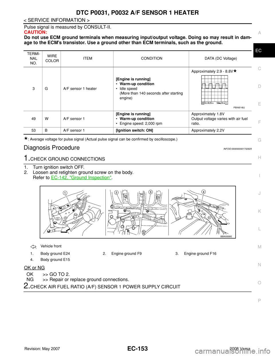
1.CHECK GROUND CONNECTIONS
1. Turn ignition switch OFF.
2. Loosen and retighten ground screw on the body.
Refer to EC-142, "
Ground Inspection".
OK or NG
OK >> GO TO 2.
NG >> Repair or replace ground connections.
2.CHECK AIR FUEL RATIO (A/F) SENSOR 1 POWER SUPPLY CIRCUIT
TERMI-
NAL
NO.WIRE
COLORITEM CONDITION DATA (DC Voltage)
3 G A/F sensor 1 heater[Engine is running]
•Warm-up condition
• Idle speed
(More than 140 seconds after starting
engine)Approximately 2.9 - 8.8V
49 W A/F sensor 1[Engine is running]
•Warm-up condition
• Engine speed: 2,000 rpmApproximately 1.8V
Output voltage varies with air fuel
ratio.
53 B A/F sensor 1[Ignition switch: ON]Approximately 2.2V
PBIA8148J
:Vehicle front
1. Body ground E24 2. Engine ground F9 3. Engine ground F16
4. Body ground E15
BBIA0698E
Page 1228 of 2771
EC-154
< SERVICE INFORMATION >
DTC P0031, P0032 A/F SENSOR 1 HEATER
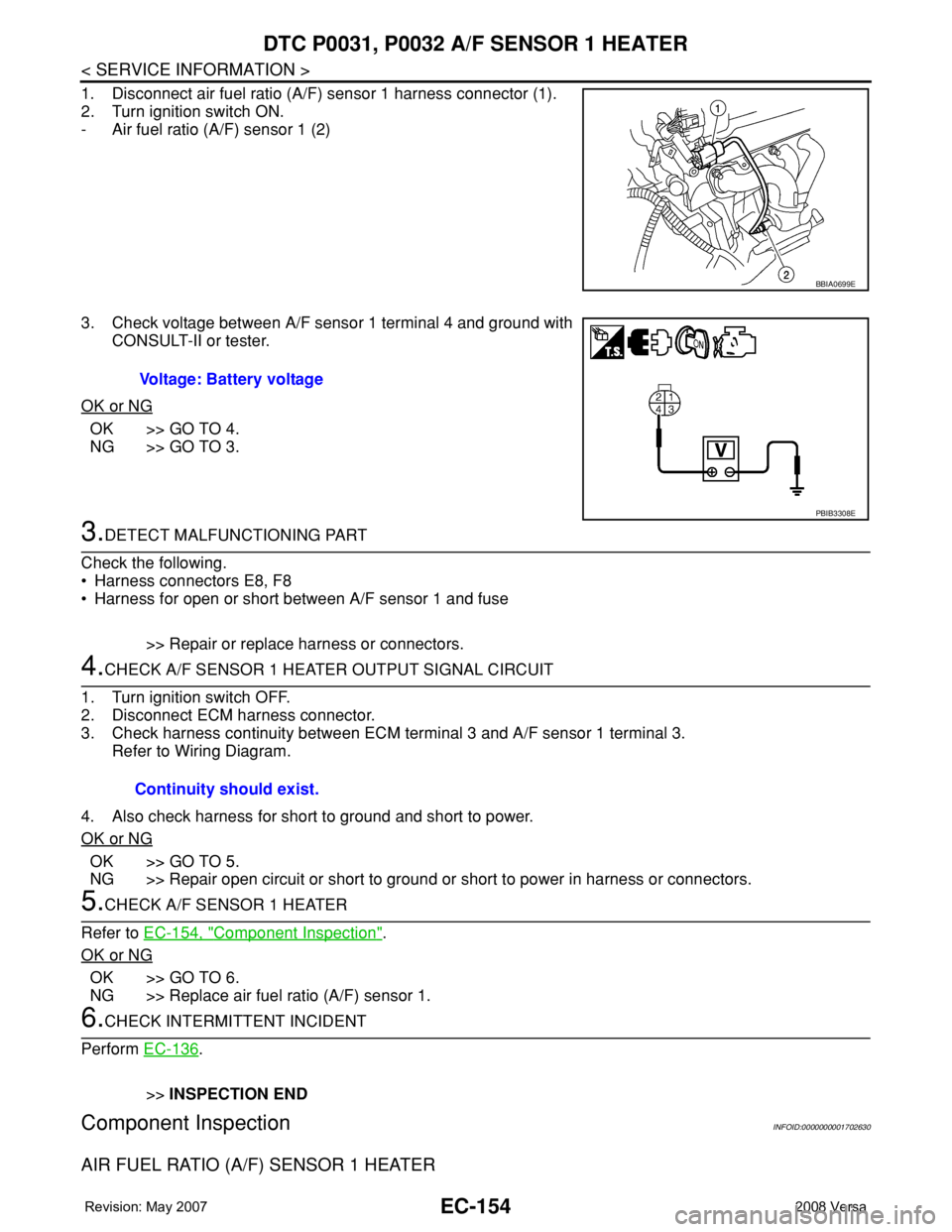
1. Disconnect air fuel ratio (A/F) sensor 1 harness connector (1).
2. Turn ignition switch ON.
- Air fuel ratio (A/F) sensor 1 (2)
3. Check voltage between A/F sensor 1 terminal 4 and ground with
CONSULT-II or tester.
OK or NG
OK >> GO TO 4.
NG >> GO TO 3.
3.DETECT MALFUNCTIONING PART
Check the following.
• Harness connectors E8, F8
• Harness for open or short between A/F sensor 1 and fuse
>> Repair or replace harness or connectors.
4.CHECK A/F SENSOR 1 HEATER OUTPUT SIGNAL CIRCUIT
1. Turn ignition switch OFF.
2. Disconnect ECM harness connector.
3. Check harness continuity between ECM terminal 3 and A/F sensor 1 terminal 3.
Refer to Wiring Diagram.
4. Also check harness for short to ground and short to power.
OK or NG
OK >> GO TO 5.
NG >> Repair open circuit or short to ground or short to power in harness or connectors.
5.CHECK A/F SENSOR 1 HEATER
Refer to EC-154, "
Component Inspection".
OK or NG
OK >> GO TO 6.
NG >> Replace air fuel ratio (A/F) sensor 1.
6.CHECK INTERMITTENT INCIDENT
Perform EC-136
.
>>INSPECTION END
Component InspectionINFOID:0000000001702630
AIR FUEL RATIO (A/F) SENSOR 1 HEATER
BBIA0699E
Voltage: Battery voltage
PBIB3308E
Continuity should exist.
Page 1229 of 2771
DTC P0031, P0032 A/F SENSOR 1 HEATER
EC-155
< SERVICE INFORMATION >
C
D
E
F
G
H
I
J
K
L
MA
EC
N
P O
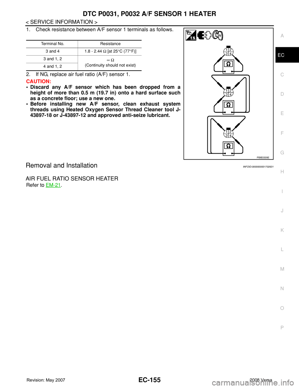
1. Check resistance between A/F sensor 1 terminals as follows.
2. If NG, replace air fuel ratio (A/F) sensor 1.
CAUTION:
• Discard any A/F sensor which has been dropped from a
height of more than 0.5 m (19.7 in) onto a hard surface such
as a concrete floor; use a new one.
• Before installing new A/F sensor, clean exhaust system
threads using Heated Oxygen Sensor Thread Cleaner tool J-
43897-18 or J-43897-12 and approved anti-seize lubricant.
Removal and InstallationINFOID:0000000001702631
AIR FUEL RATIO SENSOR HEATER
Refer to EM-21.
Terminal No. Resistance
3 and 4 1.8 - 2.44 Ω [at 25°C (77°F)]
3 and 1, 2
∞ Ω
(Continuity should not exist)
4 and 1, 2
PBIB3309E
Page 1249 of 2771
DTC P0102, P0103 MAF SENSOR
EC-175
< SERVICE INFORMATION >
C
D
E
F
G
H
I
J
K
L
MA
EC
N
P O
DTC P0102, P0103 MAF SENSOR
Component DescriptionINFOID:0000000001702657
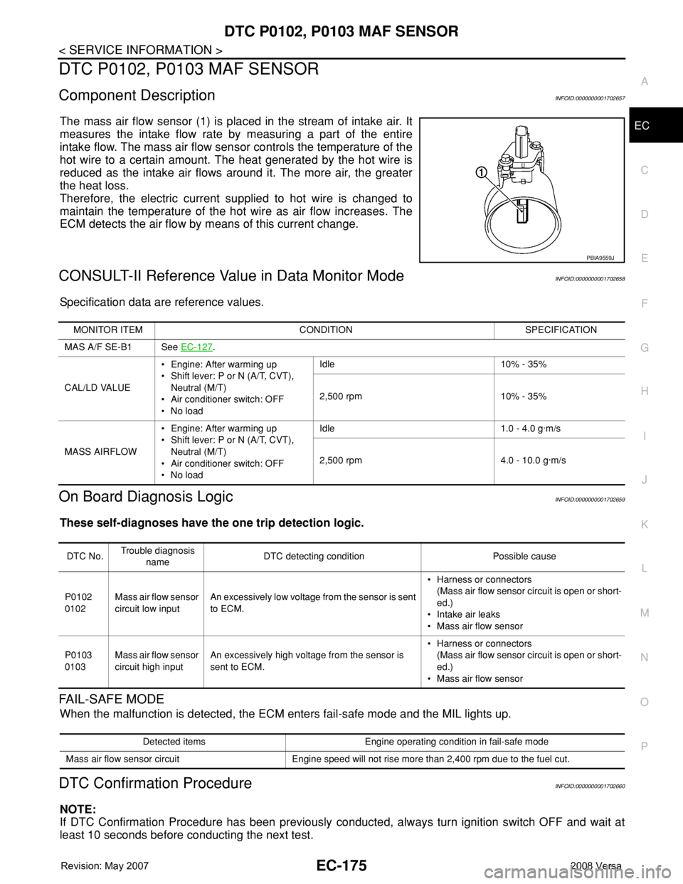
The mass air flow sensor (1) is placed in the stream of intake air. It
measures the intake flow rate by measuring a part of the entire
intake flow. The mass air flow sensor controls the temperature of the
hot wire to a certain amount. The heat generated by the hot wire is
reduced as the intake air flows around it. The more air, the greater
the heat loss.
Therefore, the electric current supplied to hot wire is changed to
maintain the temperature of the hot wire as air flow increases. The
ECM detects the air flow by means of this current change.
CONSULT-II Reference Value in Data Monitor ModeINFOID:0000000001702658
Specification data are reference values.
On Board Diagnosis LogicINFOID:0000000001702659
These self-diagnoses have the one trip detection logic.
FAIL-SAFE MODE
When the malfunction is detected, the ECM enters fail-safe mode and the MIL lights up.
DTC Confirmation ProcedureINFOID:0000000001702660
NOTE:
If DTC Confirmation Procedure has been previously conducted, always turn ignition switch OFF and wait at
least 10 seconds before conducting the next test.
PBIA9559J
MONITOR ITEM CONDITION SPECIFICATION
MAS A/F SE-B1 See EC-127
.
CAL/LD VALUE• Engine: After warming up
• Shift lever: P or N (A/T, CVT),
Neutral (M/T)
• Air conditioner switch: OFF
•No loadIdle 10% - 35%
2,500 rpm 10% - 35%
MASS AIRFLOW• Engine: After warming up
• Shift lever: P or N (A/T, CVT),
Neutral (M/T)
• Air conditioner switch: OFF
•No loadIdle 1.0 - 4.0 g·m/s
2,500 rpm 4.0 - 10.0 g·m/s
DTC No.Trouble diagnosis
nameDTC detecting condition Possible cause
P0102
0102Mass air flow sensor
circuit low inputAn excessively low voltage from the sensor is sent
to ECM.• Harness or connectors
(Mass air flow sensor circuit is open or short-
ed.)
• Intake air leaks
• Mass air flow sensor
P0103
0103Mass air flow sensor
circuit high inputAn excessively high voltage from the sensor is
sent to ECM.• Harness or connectors
(Mass air flow sensor circuit is open or short-
ed.)
• Mass air flow sensor
Detected items Engine operating condition in fail-safe mode
Mass air flow sensor circuit Engine speed will not rise more than 2,400 rpm due to the fuel cut.
Page 1272 of 2771
EC-198
< SERVICE INFORMATION >
DTC P0125 ECT SENSOR
DTC P0125 ECT SENSOR
DescriptionINFOID:0000000001702687
NOTE:
If DTC P0125 is displayed with P0117 or P0118, first perform the trouble diagnosis for DTC P0117 or
P0118. Refer to EC-187
.
COMPONENT DESCRIPTION
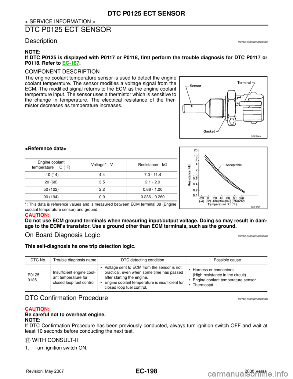
The engine coolant temperature sensor is used to detect the engine
coolant temperature. The sensor modifies a voltage signal from the
ECM. The modified signal returns to the ECM as the engine coolant
temperature input. The sensor uses a thermistor which is sensitive to
the change in temperature. The electrical resistance of the ther-
mistor decreases as temperature increases.
*: This data is reference values and is measured between ECM terminal 38 (Engine
coolant temperature sensor) and ground.
CAUTION:
Do not use ECM ground terminals when measuring input/output voltage. Doing so may result in dam-
age to the ECM's transistor. Use a ground other than ECM terminals, such as the ground.
On Board Diagnosis LogicINFOID:0000000001702688
This self-diagnosis ha one trip detection logic.
DTC Confirmation ProcedureINFOID:0000000001702689
CAUTION:
Be careful not to overheat engine.
NOTE:
If DTC Confirmation Procedure has been previously conducted, always turn ignition switch OFF and wait at
least 10 seconds before conducting the next test.
WITH CONSULT-II
1. Turn ignition switch ON.
SEF594K
Engine coolant
temperature°C (°F)Voltage* V Resistance kΩ
−10 (14) 4.4 7.0 - 11.4
20 (68) 3.5 2.1 - 2.9
50 (122) 2.2 0.68 - 1.00
90 (194) 0.9 0.236 - 0.260
SEF012P
DTC No. Trouble diagnosis name DTC detecting condition Possible cause
P0125
0125Insufficient engine cool-
ant temperature for
closed loop fuel control• Voltage sent to ECM from the sensor is not
practical, even when some time has passed
after starting the engine.
• Engine coolant temperature is insufficient for
closed loop fuel control.• Harness or connectors
(High resistance in the circuit)
• Engine coolant temperature sensor
•Thermostat
Page 1280 of 2771
EC-206
< SERVICE INFORMATION >
DTC P0130 A/F SENSOR 1
DTC P0130 A/F SENSOR 1
Component DescriptionINFOID:0000000001702704
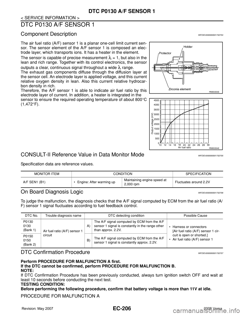
The air fuel ratio (A/F) sensor 1 is a planar one-cell limit current sen-
sor. The sensor element of the A/F sensor 1 is composed an elec-
trode layer, which transports ions. It has a heater in the element.
The sensor is capable of precise measurement = 1, but also in the
lean and rich range. Together with its control electronics, the sensor
outputs a clear, continuous signal throughout a wide range.
The exhaust gas components diffuse through the diffusion layer at
the sensor cell. An electrode layer is applied voltage, and this current
relative oxygen density in lean. Also this current relative hydrocar-
bon density in rich.
Therefore, the A/F sensor 1 is able to indicate air fuel ratio by this
electrode layer of current. In addition, a heater is integrated in the
sensor to ensure the required operating temperature of about 800°C
(1,472°F).
CONSULT-II Reference Value in Data Monitor ModeINFOID:0000000001702705
Specification data are reference values.
On Board Diagnosis LogicINFOID:0000000001702706
To judge the malfunction, the diagnosis checks that the A/F signal computed by ECM from the air fuel ratio (A/
F) sensor 1 signal fluctuates according to fuel feedback control.
DTC Confirmation ProcedureINFOID:0000000001702707
Perform PROCEDURE FOR MALFUNCTION A first.
If the DTC cannot be confirmed, perform PROCEDURE FOR MALFUNCTION B.
NOTE:
If DTC Confirmation Procedure has been previously conducted, always turn ignition switch OFF and wait at
least 10 seconds before conducting the next test.
TESTING CONDITION:
Before performing the following procedure, confirm that battery voltage is more than 11V at idle.
PROCEDURE FOR MALFUNCTION A
PBIB3353E
PBIB3354E
MONITOR ITEM CONDITION SPECIFICATION
A/F SEN1 (B1) • Engine: After warming upMaintaining engine speed at
2,000 rpmFluctuates around 2.2V
DTC No. Trouble diagnosis name DTC detecting condition Possible Cause
P0130
0130
(Bank 1)
Air fuel ratio (A/F) sensor 1
circuitA)The A/F signal computed by ECM from the A/F
sensor 1 signal is constantly in the range other
than approx. 2.2V.• Harness or connectors
[Air fuel ratio (A/F) sensor 1 cir-
cuit is open or shorted.]
• Air fuel ratio (A/F) sensor 1 P0150
0150
(Bank 2)B)The A/F signal computed by ECM from the A/F
sensor 1 signal is constantly approx. 2.2V.
Page 1281 of 2771
DTC P0130 A/F SENSOR 1
EC-207
< SERVICE INFORMATION >
C
D
E
F
G
H
I
J
K
L
MA
EC
N
P O With CONSULT-II
1. Start engine and warm it up to normal operating temperature.
2. Select “DATA MONITOR” mode with CONSULT-II.
3. Let engine idle for 2 minutes.
4. If 1st trip DTC is detected, go to EC-210, "
Diagnosis Procedure".
With GST
Follow the procedure “With CONSULT-II” above.
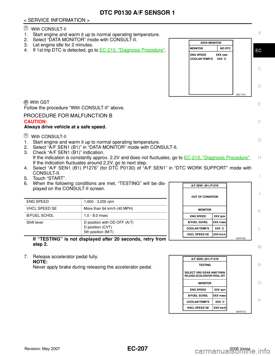
PROCEDURE FOR MALFUNCTION B
CAUTION:
Always drive vehicle at a safe speed.
With CONSULT-II
1. Start engine and warm it up to normal operating temperature.
2. Select “A/F SEN1 (B1)” in “DATA MONITOR” mode with CONSULT-II.
3. Check “A/F SEN1 (B1)” indication.
If the indication is constantly approx. 2.2V and does not fluctuates, go to EC-210, "
Diagnosis Procedure".
If the indication fluctuates around 2.2V, go to next step.
4. Select “A/F SEN1 (B1) P1276” (for DTC P0130) of “A/F SEN1” in “DTC WORK SUPPORT” mode with
CONSULT-II.
5. Touch “START”.
6. When the following conditions are met, “TESTING” will be dis-
played on the CONSULT-II screen.
If “TESTING” is not displayed after 20 seconds, retry from
step 2.
7. Release accelerator pedal fully.
NOTE:
Never apply brake during releasing the accelerator pedal.
SEF174Y
ENG SPEED 1,600 - 3,200 rpm
VHCL SPEED SE More than 64 km/h (40 MPH)
B/FUEL SCHDL 1.0 - 8.0 msec
Shift lever D position with OD OFF (A/T)
D position (CVT)
5th position (M/T)
SEF576Z
SEF577Z
Page 1284 of 2771
EC-210
< SERVICE INFORMATION >
DTC P0130 A/F SENSOR 1
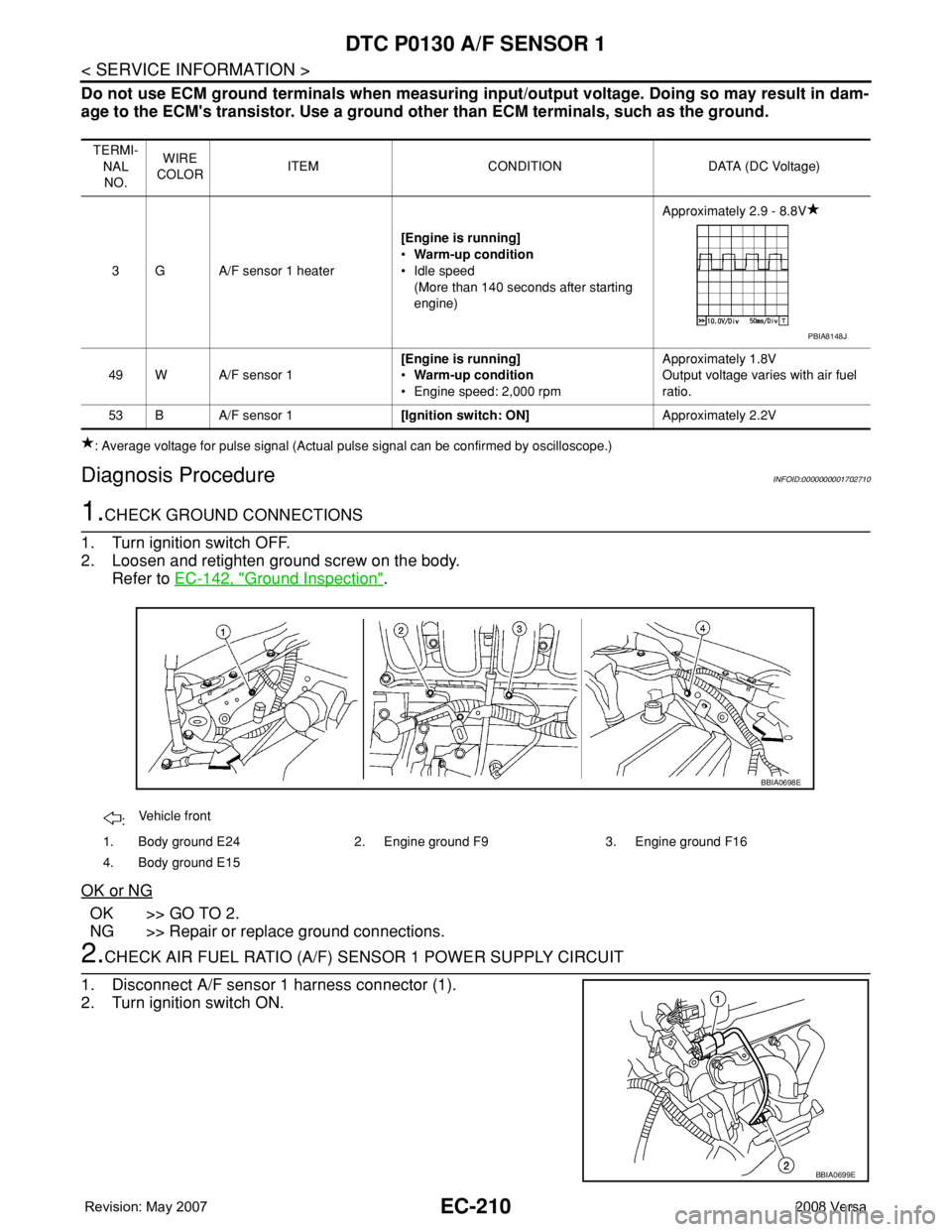
Do not use ECM ground terminals when measuring input/output voltage. Doing so may result in dam-
age to the ECM's transistor. Use a ground other than ECM terminals, such as the ground.
: Average voltage for pulse signal (Actual pulse signal can be confirmed by oscilloscope.)
Diagnosis ProcedureINFOID:0000000001702710
1.CHECK GROUND CONNECTIONS
1. Turn ignition switch OFF.
2. Loosen and retighten ground screw on the body.
Refer to EC-142, "
Ground Inspection".
OK or NG
OK >> GO TO 2.
NG >> Repair or replace ground connections.
2.CHECK AIR FUEL RATIO (A/F) SENSOR 1 POWER SUPPLY CIRCUIT
1. Disconnect A/F sensor 1 harness connector (1).
2. Turn ignition switch ON.
TERMI-
NAL
NO.WIRE
COLORITEM CONDITION DATA (DC Voltage)
3 G A/F sensor 1 heater[Engine is running]
•Warm-up condition
• Idle speed
(More than 140 seconds after starting
engine)Approximately 2.9 - 8.8V
49 W A/F sensor 1[Engine is running]
•Warm-up condition
• Engine speed: 2,000 rpmApproximately 1.8V
Output voltage varies with air fuel
ratio.
53 B A/F sensor 1[Ignition switch: ON]Approximately 2.2V
PBIA8148J
:Vehicle front
1. Body ground E24 2. Engine ground F9 3. Engine ground F16
4. Body ground E15
BBIA0698E
BBIA0699E
Page 1285 of 2771
DTC P0130 A/F SENSOR 1
EC-211
< SERVICE INFORMATION >
C
D
E
F
G
H
I
J
K
L
MA
EC
N
P O
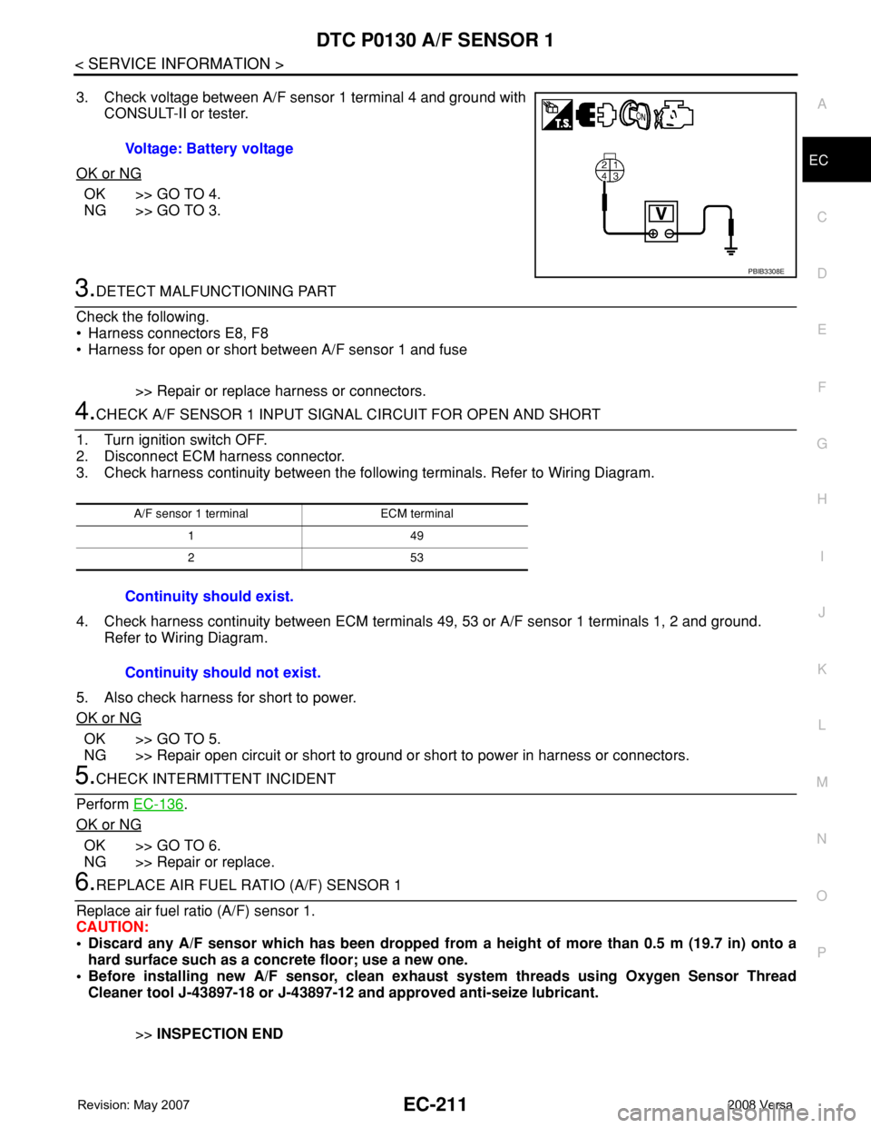
3. Check voltage between A/F sensor 1 terminal 4 and ground with
CONSULT-II or tester.
OK or NG
OK >> GO TO 4.
NG >> GO TO 3.
3.DETECT MALFUNCTIONING PART
Check the following.
• Harness connectors E8, F8
• Harness for open or short between A/F sensor 1 and fuse
>> Repair or replace harness or connectors.
4.CHECK A/F SENSOR 1 INPUT SIGNAL CIRCUIT FOR OPEN AND SHORT
1. Turn ignition switch OFF.
2. Disconnect ECM harness connector.
3. Check harness continuity between the following terminals. Refer to Wiring Diagram.
4. Check harness continuity between ECM terminals 49, 53 or A/F sensor 1 terminals 1, 2 and ground.
Refer to Wiring Diagram.
5. Also check harness for short to power.
OK or NG
OK >> GO TO 5.
NG >> Repair open circuit or short to ground or short to power in harness or connectors.
5.CHECK INTERMITTENT INCIDENT
Perform EC-136
.
OK or NG
OK >> GO TO 6.
NG >> Repair or replace.
6.REPLACE AIR FUEL RATIO (A/F) SENSOR 1
Replace air fuel ratio (A/F) sensor 1.
CAUTION:
• Discard any A/F sensor which has been dropped from a height of more than 0.5 m (19.7 in) onto a
hard surface such as a concrete floor; use a new one.
• Before installing new A/F sensor, clean exhaust system threads using Oxygen Sensor Thread
Cleaner tool J-43897-18 or J-43897-12 and approved anti-seize lubricant.
>>INSPECTION END Voltage: Battery voltage
PBIB3308E
A/F sensor 1 terminal ECM terminal
149
253
Continuity should exist.
Continuity should not exist.