fuel NISSAN TIIDA 2008 Service Manual PDF
[x] Cancel search | Manufacturer: NISSAN, Model Year: 2008, Model line: TIIDA, Model: NISSAN TIIDA 2008Pages: 2771, PDF Size: 60.61 MB
Page 1140 of 2771

EC-66
< SERVICE INFORMATION >
ON BOARD DIAGNOSTIC (OBD) SYSTEM
All components and systems should be monitored at least once by the OBD system.
• The B counter will be cleared when the malfunction is detected once regardless of the driving pattern.
• The B counter will be counted up when driving pattern B is satisfied without any malfunction.
• The MIL will go off when the B counter reaches 3. (*2 in “OBD SYSTEM OPERATION CHART”)
Driving pattern C means the vehicle operation as follows:
The following conditions should be satisfied at the same time:
Engine speed: (Engine speed in the freeze frame data) ±375 rpm
Calculated load value: (Calculated load value in the freeze frame data) x (1±0.1) [%]
Engine coolant temperature (T) condition:
• When the freeze frame data shows lower than 70°C (158°F), “T” should be lower than 70°C (158°F).
• When the freeze frame data shows higher than or equal to 70°C (158°F), “T” should be higher than or equal
to 70°C (158°F).
Example:
If the stored freeze frame data is as follows:
Engine speed: 850 rpm, Calculated load value: 30%, Engine coolant temperature: 80°C (176°F)
To be satisfied with driving pattern C, the vehicle should run under the following conditions:
Engine speed: 475 - 1,225 rpm, Calculated load value: 27 - 33%, Engine coolant temperature: more than 70°C
(158°F)
• The C counter will be cleared when the malfunction is detected regardless of vehicle conditions above.
• The C counter will be counted up when vehicle conditions above is satisfied without the same malfunction.
• The DTC will not be displayed after C counter reaches 80.
• The 1st trip DTC will be cleared when C counter is counted once without the same malfunction after DTC is
stored in ECM.
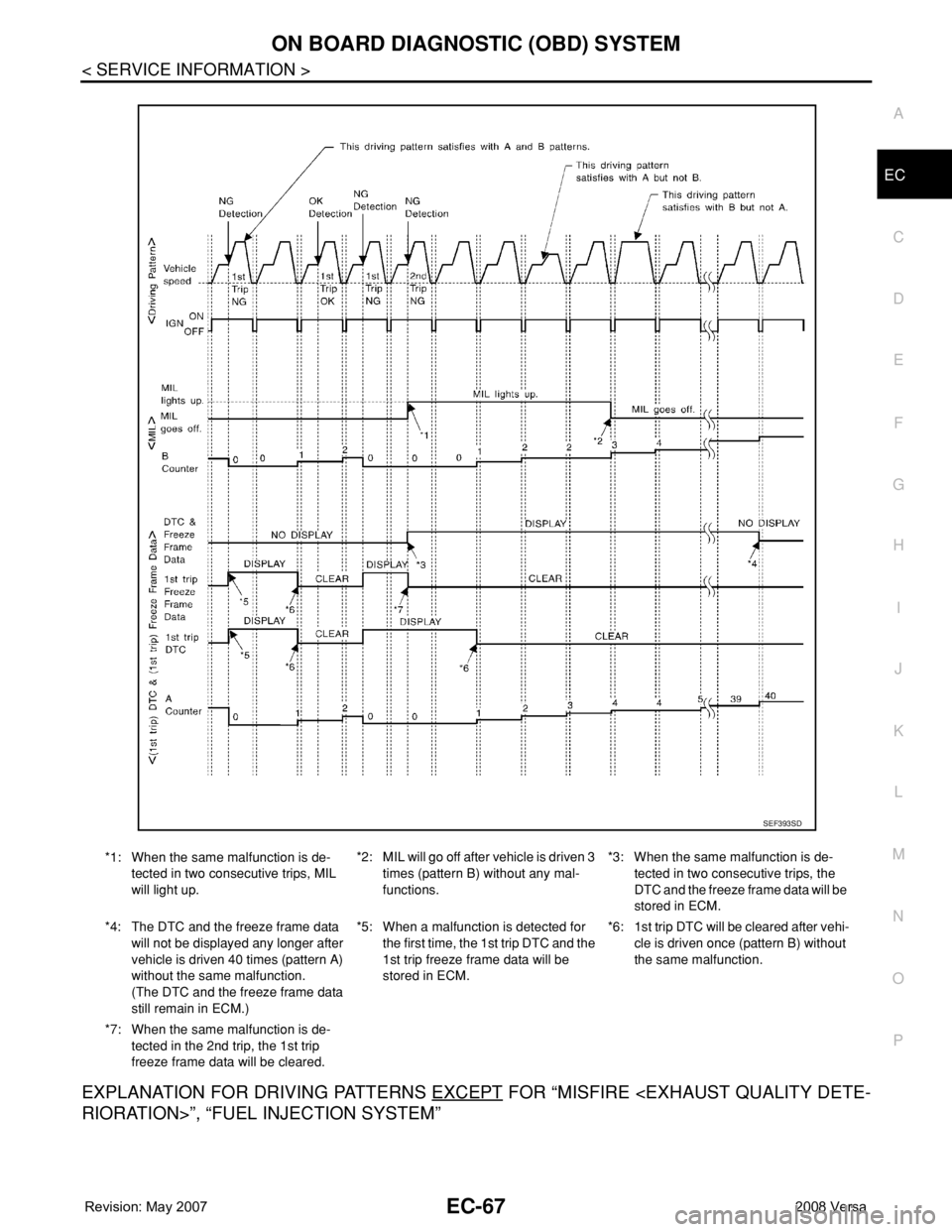
RELATIONSHIP BETWEEN MIL, DTC, 1ST TRIP DTC AND DRIVING PATTERNS EXCEPT FOR
“MISFIRE
Page 1141 of 2771
ON BOARD DIAGNOSTIC (OBD) SYSTEM
EC-67
< SERVICE INFORMATION >
C
D
E
F
G
H
I
J
K
L
MA
EC
N
P O
EXPLANATION FOR DRIVING PATTERNS EXCEPT FOR “MISFIRE
*1: When the same malfunction is de-
tected in two consecutive trips, MIL
will light up.*2: MIL will go off after vehicle is driven 3
times (pattern B) without any mal-
functions.*3: When the same malfunction is de-
tected in two consecutive trips, the
DTC and the freeze frame data will be
stored in ECM.
*4: The DTC and the freeze frame data
will not be displayed any longer after
vehicle is driven 40 times (pattern A)
without the same malfunction.
(The DTC and the freeze frame data
still remain in ECM.)*5: When a malfunction is detected for
the first time, the 1st trip DTC and the
1st trip freeze frame data will be
stored in ECM.*6: 1st trip DTC will be cleared after vehi-
cle is driven once (pattern B) without
the same malfunction.
*7: When the same malfunction is de-
tected in the 2nd trip, the 1st trip
freeze frame data will be cleared.
SEF393SD
Page 1152 of 2771
EC-78
< SERVICE INFORMATION >
BASIC SERVICE PROCEDURE
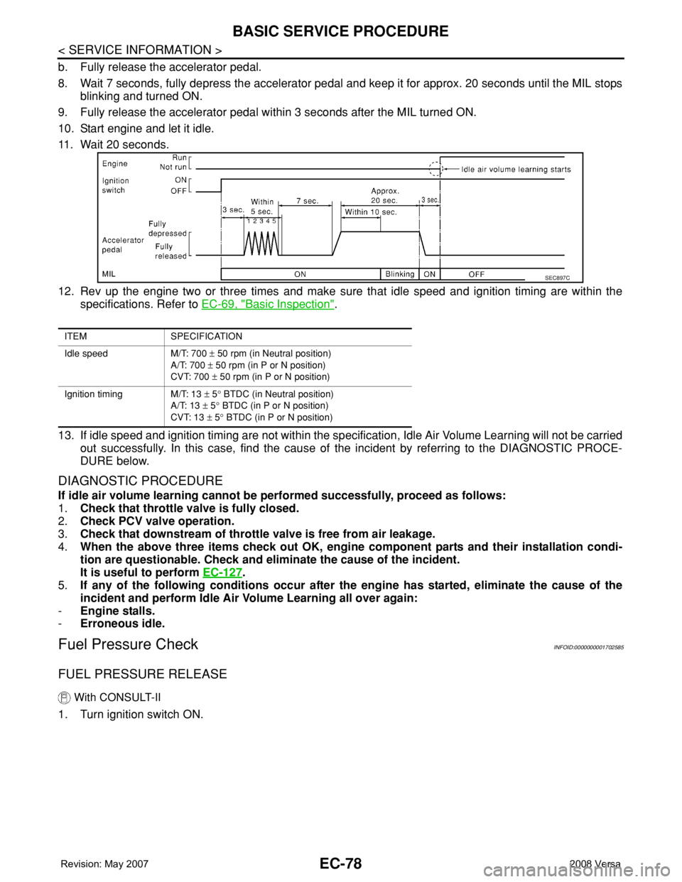
b. Fully release the accelerator pedal.
8. Wait 7 seconds, fully depress the accelerator pedal and keep it for approx. 20 seconds until the MIL stops
blinking and turned ON.
9. Fully release the accelerator pedal within 3 seconds after the MIL turned ON.
10. Start engine and let it idle.
11. Wait 20 seconds.
12. Rev up the engine two or three times and make sure that idle speed and ignition timing are within the
specifications. Refer to EC-69, "
Basic Inspection".
13. If idle speed and ignition timing are not within the specification, Idle Air Volume Learning will not be carried
out successfully. In this case, find the cause of the incident by referring to the DIAGNOSTIC PROCE-
DURE below.
DIAGNOSTIC PROCEDURE
If idle air volume learning cannot be performed successfully, proceed as follows:
1.Check that throttle valve is fully closed.
2.Check PCV valve operation.
3.Check that downstream of throttle valve is free from air leakage.
4.When the above three items check out OK, engine component parts and their installation condi-
tion are questionable. Check and eliminate the cause of the incident.
It is useful to perform EC-127
.
5.If any of the following conditions occur after the engine has started, eliminate the cause of the
incident and perform Idle Air Volume Learning all over again:
-Engine stalls.
-Erroneous idle.
Fuel Pressure CheckINFOID:0000000001702585
FUEL PRESSURE RELEASE
With CONSULT-II
1. Turn ignition switch ON.
ITEM SPECIFICATION
Idle speed M/T: 700 ± 50 rpm (in Neutral position)
A/T: 700 ± 50 rpm (in P or N position)
CVT: 700 ± 50 rpm (in P or N position)
Ignition timing M/T: 13 ± 5° BTDC (in Neutral position)
A/T: 13 ± 5° BTDC (in P or N position)
CVT: 13 ± 5° BTDC (in P or N position)
SEC897C
Page 1153 of 2771
BASIC SERVICE PROCEDURE
EC-79
< SERVICE INFORMATION >
C
D
E
F
G
H
I
J
K
L
MA
EC
N
P O
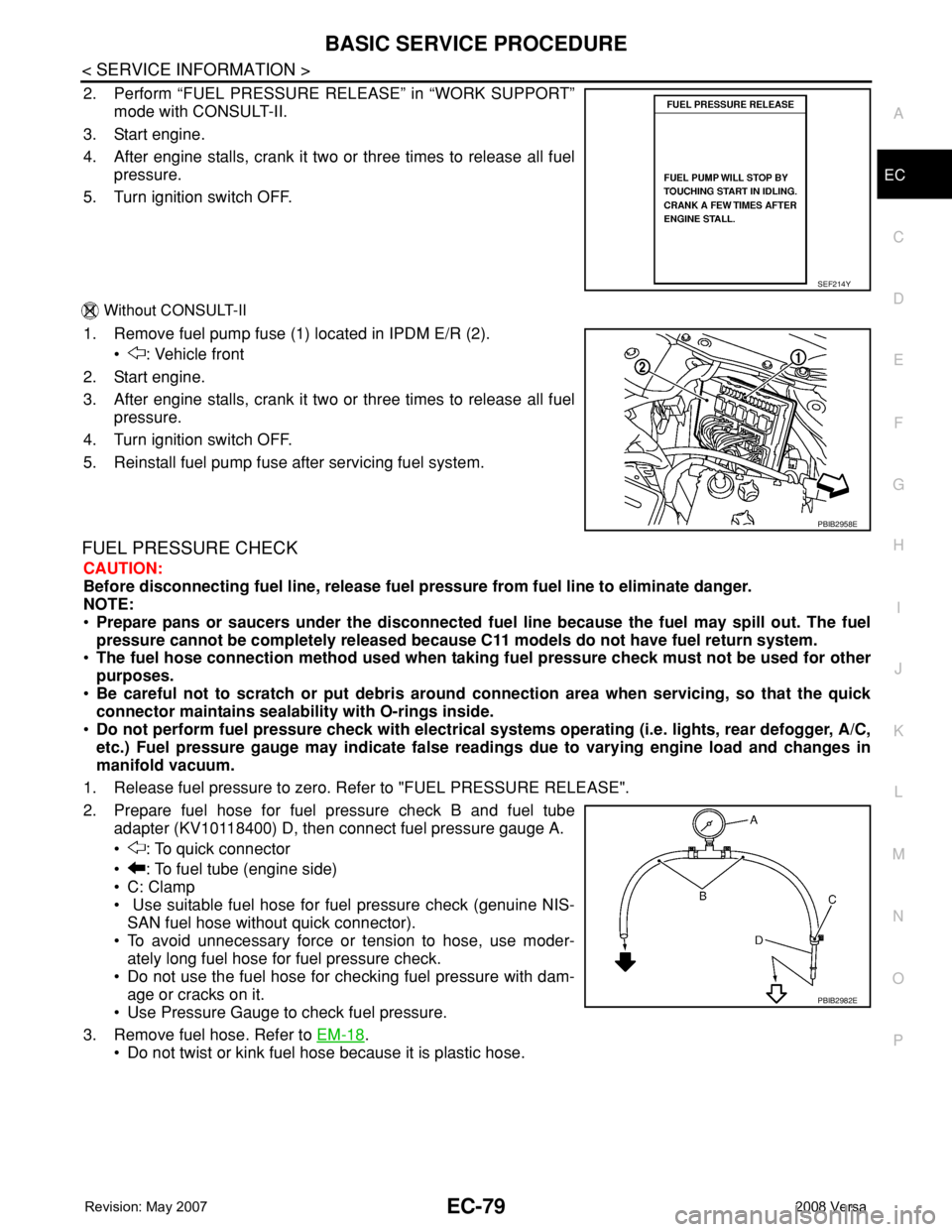
2. Perform “FUEL PRESSURE RELEASE” in “WORK SUPPORT”
mode with CONSULT-II.
3. Start engine.
4. After engine stalls, crank it two or three times to release all fuel
pressure.
5. Turn ignition switch OFF.
Without CONSULT-II
1. Remove fuel pump fuse (1) located in IPDM E/R (2).
• : Vehicle front
2. Start engine.
3. After engine stalls, crank it two or three times to release all fuel
pressure.
4. Turn ignition switch OFF.
5. Reinstall fuel pump fuse after servicing fuel system.
FUEL PRESSURE CHECK
CAUTION:
Before disconnecting fuel line, release fuel pressure from fuel line to eliminate danger.
NOTE:
•Prepare pans or saucers under the disconnected fuel line because the fuel may spill out. The fuel
pressure cannot be completely released because C11 models do not have fuel return system.
•The fuel hose connection method used when taking fuel pressure check must not be used for other
purposes.
•Be careful not to scratch or put debris around connection area when servicing, so that the quick
connector maintains sealability with O-rings inside.
•Do not perform fuel pressure check with electrical systems operating (i.e. lights, rear defogger, A/C,
etc.) Fuel pressure gauge may indicate false readings due to varying engine load and changes in
manifold vacuum.
1. Release fuel pressure to zero. Refer to "FUEL PRESSURE RELEASE".
2. Prepare fuel hose for fuel pressure check B and fuel tube
adapter (KV10118400) D, then connect fuel pressure gauge A.
• : To quick connector
• : To fuel tube (engine side)
• C: Clamp
• Use suitable fuel hose for fuel pressure check (genuine NIS-
SAN fuel hose without quick connector).
• To avoid unnecessary force or tension to hose, use moder-
ately long fuel hose for fuel pressure check.
• Do not use the fuel hose for checking fuel pressure with dam-
age or cracks on it.
• Use Pressure Gauge to check fuel pressure.
3. Remove fuel hose. Refer to EM-18
.
• Do not twist or kink fuel hose because it is plastic hose.
SEF214Y
PBIB2958E
PBIB2982E
Page 1154 of 2771
EC-80
< SERVICE INFORMATION >
BASIC SERVICE PROCEDURE
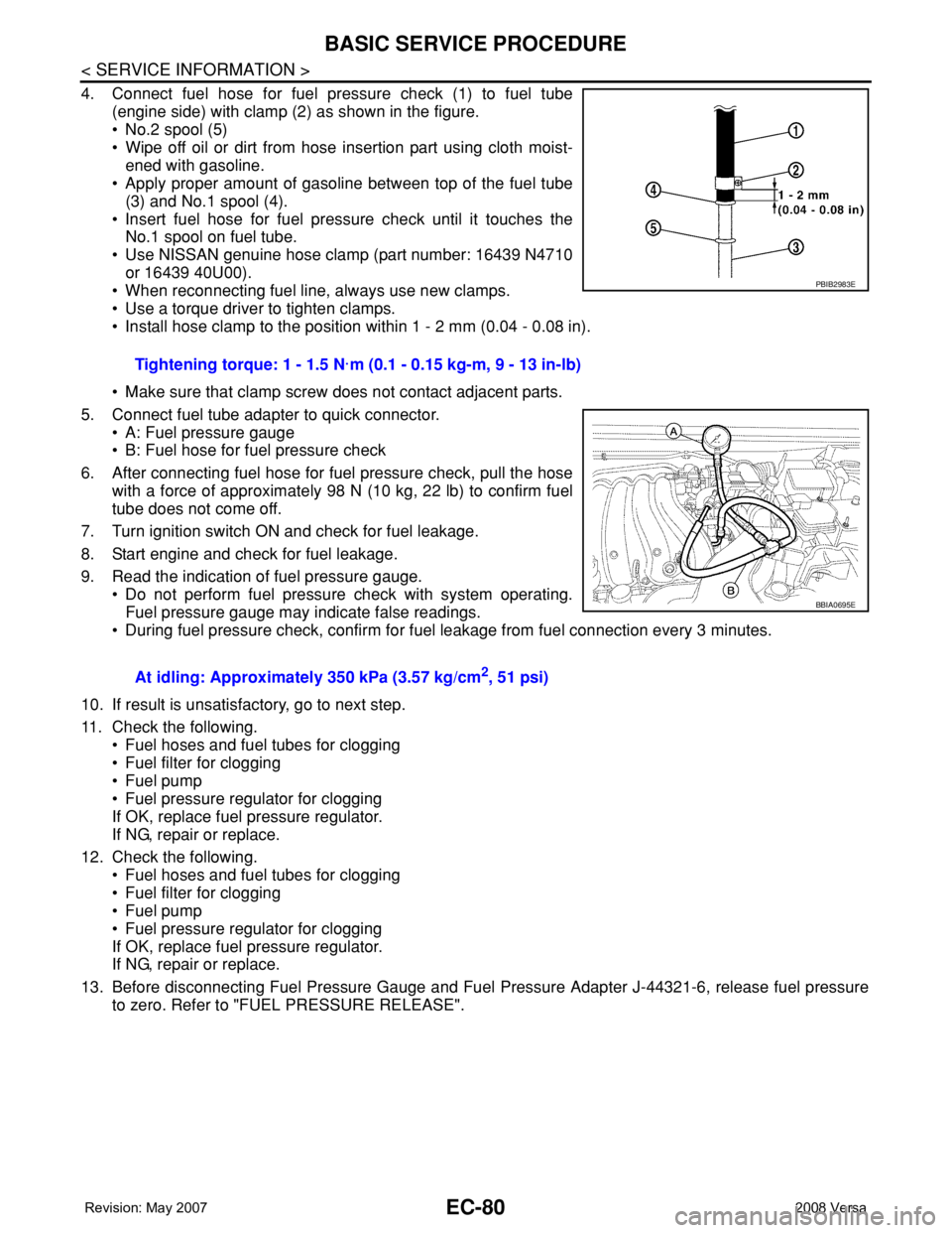
4. Connect fuel hose for fuel pressure check (1) to fuel tube
(engine side) with clamp (2) as shown in the figure.
• No.2 spool (5)
• Wipe off oil or dirt from hose insertion part using cloth moist-
ened with gasoline.
• Apply proper amount of gasoline between top of the fuel tube
(3) and No.1 spool (4).
• Insert fuel hose for fuel pressure check until it touches the
No.1 spool on fuel tube.
• Use NISSAN genuine hose clamp (part number: 16439 N4710
or 16439 40U00).
• When reconnecting fuel line, always use new clamps.
• Use a torque driver to tighten clamps.
• Install hose clamp to the position within 1 - 2 mm (0.04 - 0.08 in).
• Make sure that clamp screw does not contact adjacent parts.
5. Connect fuel tube adapter to quick connector.
• A: Fuel pressure gauge
• B: Fuel hose for fuel pressure check
6. After connecting fuel hose for fuel pressure check, pull the hose
with a force of approximately 98 N (10 kg, 22 lb) to confirm fuel
tube does not come off.
7. Turn ignition switch ON and check for fuel leakage.
8. Start engine and check for fuel leakage.
9. Read the indication of fuel pressure gauge.
• Do not perform fuel pressure check with system operating.
Fuel pressure gauge may indicate false readings.
• During fuel pressure check, confirm for fuel leakage from fuel connection every 3 minutes.
10. If result is unsatisfactory, go to next step.
11. Check the following.
• Fuel hoses and fuel tubes for clogging
• Fuel filter for clogging
• Fuel pump
• Fuel pressure regulator for clogging
If OK, replace fuel pressure regulator.
If NG, repair or replace.
12. Check the following.
• Fuel hoses and fuel tubes for clogging
• Fuel filter for clogging
• Fuel pump
• Fuel pressure regulator for clogging
If OK, replace fuel pressure regulator.
If NG, repair or replace.
13. Before disconnecting Fuel Pressure Gauge and Fuel Pressure Adapter J-44321-6, release fuel pressure
to zero. Refer to "FUEL PRESSURE RELEASE".Tightening torque: 1 - 1.5 N·m (0.1 - 0.15 kg-m, 9 - 13 in-lb)
At idling: Approximately 350 kPa (3.57 kg/cm
2, 51 psi)
PBIB2983E
BBIA0695E
Page 1155 of 2771
TROUBLE DIAGNOSIS
EC-81
< SERVICE INFORMATION >
C
D
E
F
G
H
I
J
K
L
MA
EC
N
P O
TROUBLE DIAGNOSIS
Trouble Diagnosis IntroductionINFOID:0000000001702586
INTRODUCTION
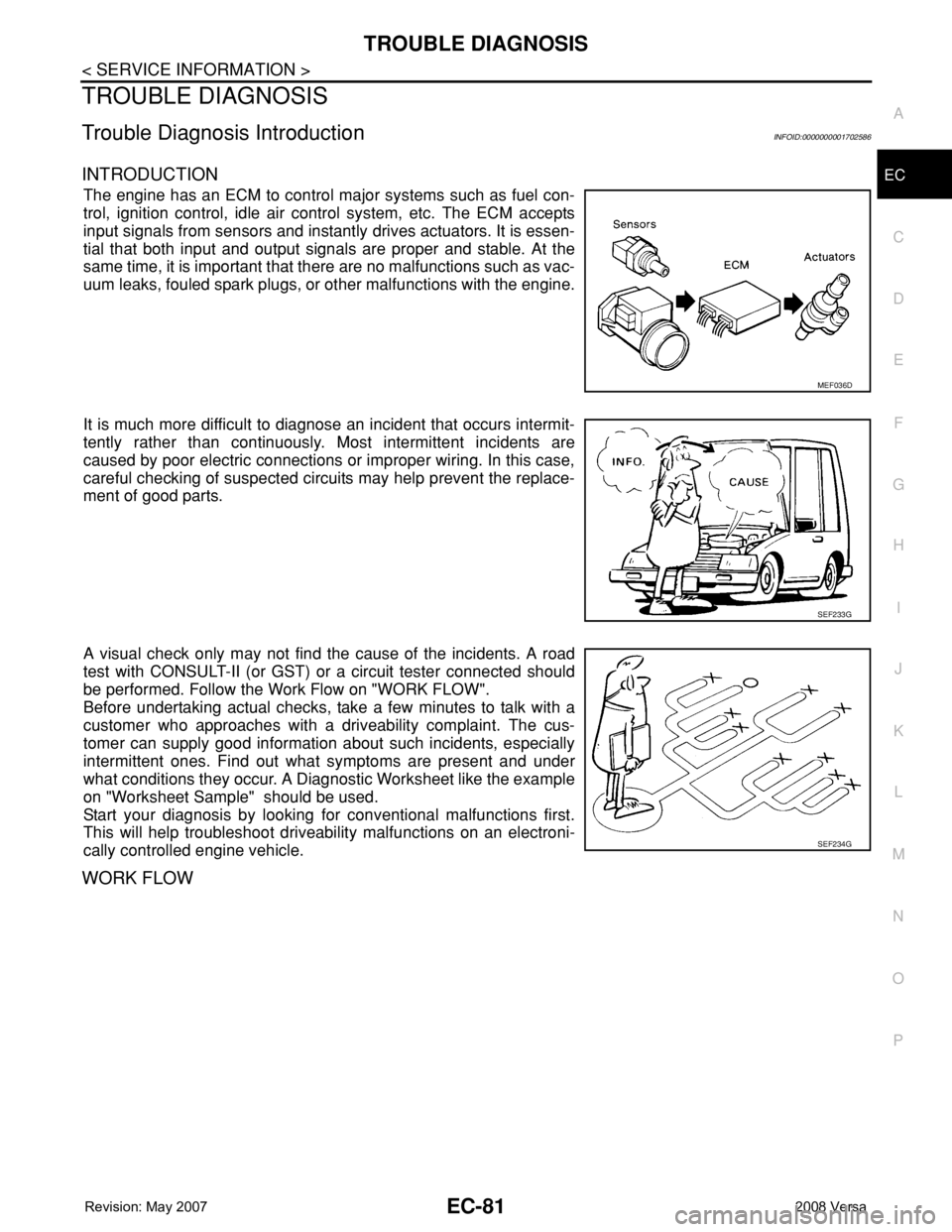
The engine has an ECM to control major systems such as fuel con-
trol, ignition control, idle air control system, etc. The ECM accepts
input signals from sensors and instantly drives actuators. It is essen-
tial that both input and output signals are proper and stable. At the
same time, it is important that there are no malfunctions such as vac-
uum leaks, fouled spark plugs, or other malfunctions with the engine.
It is much more difficult to diagnose an incident that occurs intermit-
tently rather than continuously. Most intermittent incidents are
caused by poor electric connections or improper wiring. In this case,
careful checking of suspected circuits may help prevent the replace-
ment of good parts.
A visual check only may not find the cause of the incidents. A road
test with CONSULT-II (or GST) or a circuit tester connected should
be performed. Follow the Work Flow on "WORK FLOW".
Before undertaking actual checks, take a few minutes to talk with a
customer who approaches with a driveability complaint. The cus-
tomer can supply good information about such incidents, especially
intermittent ones. Find out what symptoms are present and under
what conditions they occur. A Diagnostic Worksheet like the example
on "Worksheet Sample" should be used.
Start your diagnosis by looking for conventional malfunctions first.
This will help troubleshoot driveability malfunctions on an electroni-
cally controlled engine vehicle.
WORK FLOW
MEF036D
SEF233G
SEF234G
Page 1158 of 2771
EC-84
< SERVICE INFORMATION >
TROUBLE DIAGNOSIS
7.PERFORM DATA MONITOR (SPEC) MODE
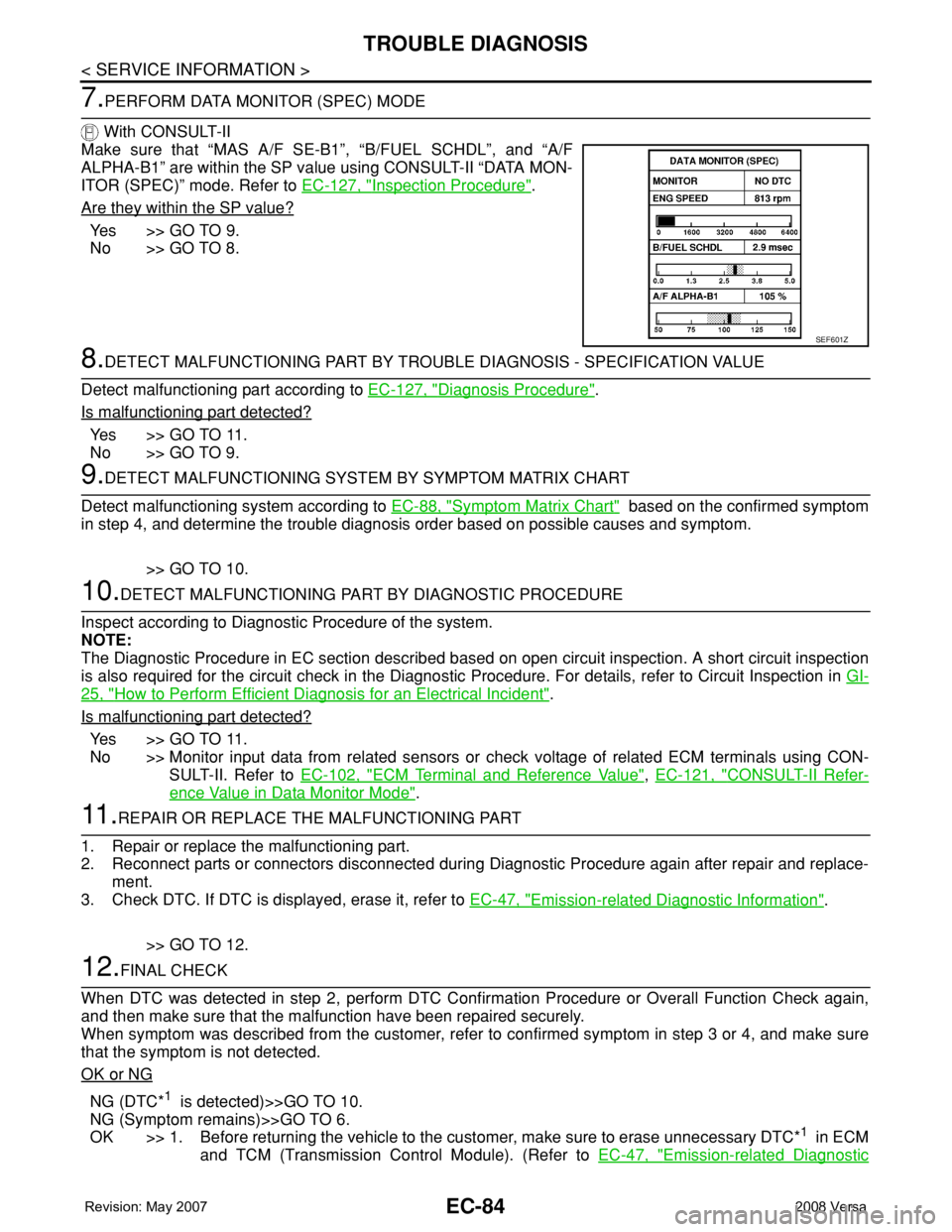
With CONSULT-II
Make sure that “MAS A/F SE-B1”, “B/FUEL SCHDL”, and “A/F
ALPHA-B1” are within the SP value using CONSULT-II “DATA MON-
ITOR (SPEC)” mode. Refer to EC-127, "
Inspection Procedure".
Are they within the SP value?
Ye s > > G O T O 9 .
No >> GO TO 8.
8.DETECT MALFUNCTIONING PART BY TROUBLE DIAGNOSIS - SPECIFICATION VALUE
Detect malfunctioning part according to EC-127, "
Diagnosis Procedure".
Is malfunctioning part detected?
Ye s > > G O T O 11 .
No >> GO TO 9.
9.DETECT MALFUNCTIONING SYSTEM BY SYMPTOM MATRIX CHART
Detect malfunctioning system according to EC-88, "
Symptom Matrix Chart" based on the confirmed symptom
in step 4, and determine the trouble diagnosis order based on possible causes and symptom.
>> GO TO 10.
10.DETECT MALFUNCTIONING PART BY DIAGNOSTIC PROCEDURE
Inspect according to Diagnostic Procedure of the system.
NOTE:
The Diagnostic Procedure in EC section described based on open circuit inspection. A short circuit inspection
is also required for the circuit check in the Diagnostic Procedure. For details, refer to Circuit Inspection in GI-
25, "How to Perform Efficient Diagnosis for an Electrical Incident".
Is malfunctioning part detected?
Ye s > > G O T O 11 .
No >> Monitor input data from related sensors or check voltage of related ECM terminals using CON-
SULT-II. Refer to EC-102, "
ECM Terminal and Reference Value", EC-121, "CONSULT-II Refer-
ence Value in Data Monitor Mode".
11 .REPAIR OR REPLACE THE MALFUNCTIONING PART
1. Repair or replace the malfunctioning part.
2. Reconnect parts or connectors disconnected during Diagnostic Procedure again after repair and replace-
ment.
3. Check DTC. If DTC is displayed, erase it, refer to EC-47, "
Emission-related Diagnostic Information".
>> GO TO 12.
12.FINAL CHECK
When DTC was detected in step 2, perform DTC Confirmation Procedure or Overall Function Check again,
and then make sure that the malfunction have been repaired securely.
When symptom was described from the customer, refer to confirmed symptom in step 3 or 4, and make sure
that the symptom is not detected.
OK or NG
NG (DTC*1 is detected)>>GO TO 10.
NG (Symptom remains)>>GO TO 6.
OK >> 1. Before returning the vehicle to the customer, make sure to erase unnecessary DTC*
1 in ECM
and TCM (Transmission Control Module). (Refer to EC-47, "
Emission-related Diagnostic
SEF601Z
Page 1159 of 2771
TROUBLE DIAGNOSIS
EC-85
< SERVICE INFORMATION >
C
D
E
F
G
H
I
J
K
L
MA
EC
N
P O
Information" and AT-36, "OBD-II Diagnostic Trouble Code (DTC)", CVT-26, "OBD-II Diagnos-
tic Trouble Code (DTC)".)
2. If the completion of SRT is needed, drive vehicle under the specific driving pattern. Refer to
EC-47, "
Emission-related Diagnostic Information".
3.INSPECTION END
*1: Include 1st trip DTC.
*2: Include 1st trip freeze frame data.
DIAGNOSTIC WORKSHEET
Description
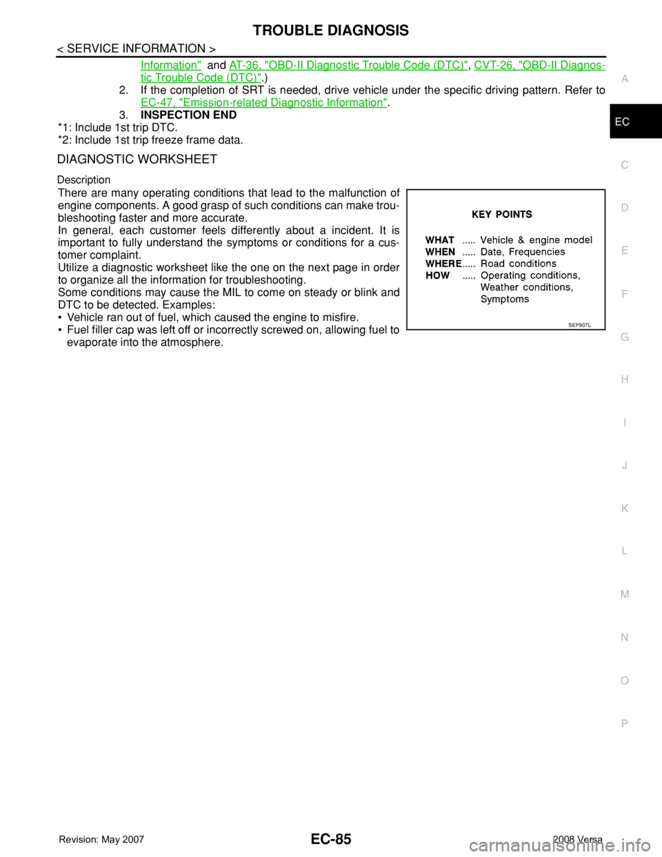
There are many operating conditions that lead to the malfunction of
engine components. A good grasp of such conditions can make trou-
bleshooting faster and more accurate.
In general, each customer feels differently about a incident. It is
important to fully understand the symptoms or conditions for a cus-
tomer complaint.
Utilize a diagnostic worksheet like the one on the next page in order
to organize all the information for troubleshooting.
Some conditions may cause the MIL to come on steady or blink and
DTC to be detected. Examples:
• Vehicle ran out of fuel, which caused the engine to misfire.
• Fuel filler cap was left off or incorrectly screwed on, allowing fuel to
evaporate into the atmosphere.
SEF907L
Page 1161 of 2771

TROUBLE DIAGNOSIS
EC-87
< SERVICE INFORMATION >
C
D
E
F
G
H
I
J
K
L
MA
EC
N
P O
Fail-Safe ChartINFOID:0000000001702588
When the DTC listed below is detected, the ECM enters fail-safe mode and the MIL lights up.
Priority Detected items (DTC)
1 • U1000 U1001 CAN communication line
• U1010 CAN communication
• P0101 P0102 P0103 Mass air flow sensor
• P0112 P0113 P0127 Intake air temperature sensor
• P0117 P0118 P0125 Engine coolant temperature sensor
• P0122 P0123 P0222 P0223 P1225 P1226 P2135 Throttle position sensor
• P0128 Thermostat function
• P0181 P0182 P0183 Fuel tank temperature sensor
• P0327 P0328 Knock sensor
• P0335 Crankshaft position sensor (POS)
• P0340 Camshaft position sensor (PHASE)
• P0460 P0461 P0462 P0463 Fuel level sensor
• P0500 Vehicle speed sensor
• P0605 ECM
• P0643 Sensor power supply
• P0705 P0850 Park/neutral position (PNP) switch
• P1610 - P1615 NATS
• P2122 P2123 P2127 P2128 P2138 Accelerator pedal position sensor
2 • P0031 P0032 Air fuel ratio (A/F) sensor 1 heater
• P0037 P0038 Heated oxygen sensor 2 heater
• P0075 Intake valve timing control solenoid valve
• P0130 P0131 P0132 P0133 P2A00 Air fuel ratio (A/F) sensor 1
• P0137 P0138 P0139 Heated oxygen sensor 2
• P0441 EVAP control system purge flow monitoring
• P0443 P0444 P0445 EVAP canister purge volume control solenoid valve
• P0447 P0448 EVAP canister vent control valve
• P0451 P0452 P0453 EVAP control system pressure sensor
• P1217 Engine over temperature (OVERHEAT)
• P1805 Brake switch
• P2100 P2103 Throttle control motor relay
• P2101 Electric throttle control function
• P2118 Throttle control motor
3 • P0011 Intake valve timing control
• P0171 P0172 Fuel injection system function
• P0300 - P0304 Misfire
• P0420 Three way catalyst function
• P0442 P0456 EVAP control system (SMALL LEAK, VERY SMALL LEAK)
• P0455 EVAP control system (GROSS LEAK)
• P0506 P0507 Idle speed control system
• P0710 P0715 P0720 P0725 P0731 P0732 P0733 P0734 P0740 P0744 P0745 P0746 P0750 P0755 P0776 P0778
P0840 P0845 P1705 P1740 P1760 P1777 P1778 A/T or CVT related sensors, solenoid valves and switches
• P1148 Closed loop control
• P1421 Cold start control
• P1564 ASCD steering switch
• P1572 ASCD brake switch
• P1574 ASCD vehicle speed sensor
• P1715 Turbine revolution sensor (A/T), Primary speed sensor (CVT)
• P2119 Electric throttle control actuator
DTC No. Detected items Engine operating condition in fail-safe mode
P0102
P0103Mass air flow sensor circuit Engine speed will not rise more than 2,400 rpm due to the fuel cut.
Page 1162 of 2771

EC-88
< SERVICE INFORMATION >
TROUBLE DIAGNOSIS
• When there is an open circuit on MIL circuit, the ECM cannot warn the driver by lighting up MIL when there
is malfunction on engine control system.
Therefore, when electrical controlled throttle and part of ECM related diagnoses are continuously detected
as NG for 5 trips, ECM warns the driver that engine control system malfunctions and MIL circuit is open by
means of operating fail-safe function.
The fail-safe function also operates when above diagnoses except MIL circuit are detected and demands the
driver to repair the malfunction.
Symptom Matrix ChartINFOID:0000000001702589
SYSTEM — BASIC ENGINE CONTROL SYSTEM
P0117
P0118Engine coolant temperature
sensor circuitEngine coolant temperature will be determined by ECM based on the time after turning
ignition switch ON or START.
CONSULT-II displays the engine coolant temperature decided by ECM.
ConditionEngine coolant temperature decided
(CONSULT-II display)
Just as ignition switch is turned ON
or START40°C (104°F)
More than approx. 4 minutes after
ignition ON or START80°C (176°F)
Except as shown above40 - 80°C (104 - 176°F)
(Depends on the time)
When the fail-safe system for engine coolant temperature sensor is activated, the cool-
ing fan operates while engine is running.
P0122
P0123
P0222
P0223
P2135Throttle position sensor The ECM controls the electric throttle control actuator in regulating the throttle opening
in order for the idle position to be within +10 degrees.
The ECM regulates the opening speed of the throttle valve to be slower than the normal
condition.
So, the acceleration will be poor.
P0643 Sensor power supply ECM stops the electric throttle control actuator control, throttle valve is maintained at a
fixed opening (approx. 5 degrees) by the return spring.
P2100
P2103Throttle control relay ECM stops the electric throttle control actuator control, throttle valve is maintained at a
fixed opening (approx. 5 degrees) by the return spring.
P2101 Electric throttle control func-
tionECM stops the electric throttle control actuator control, throttle valve is maintained at a
fixed opening (approx. 5 degrees) by the return spring.
P2118 Throttle control motor ECM stops the electric throttle control actuator control, throttle valve is maintained at a
fixed opening (approx. 5 degrees) by the return spring.
P2119 Electric throttle control actu-
ator(When electric throttle control actuator does not function properly due to the return
spring malfunction:)
ECM controls the electric throttle actuator by regulating the throttle opening around the
idle position. The engine speed will not rise more than 2,000 rpm.
(When throttle valve opening angle in fail-safe mode is not in specified range:)
ECM controls the electric throttle control actuator by regulating the throttle opening to
20 degrees or less.
(When ECM detects the throttle valve is stuck open:)
While the vehicle is driving, it slows down gradually by fuel cut. After the vehicle stops,
the engine stalls.
The engine can restart in N or P (A/T, CVT), Neutral (M/T) position, and engine speed
will not exceed 1,000 rpm or more.
P2122
P2123
P2127
P2128
P2138Accelerator pedal position
sensorThe ECM controls the electric throttle control actuator in regulating the throttle opening
in order for the idle position to be within +10 degrees.
The ECM regulates the opening speed of the throttle valve to be slower than the normal
condition.
So, the acceleration will be poor. DTC No. Detected items Engine operating condition in fail-safe mode
Engine operating condition in fail-safe mode Engine speed will not rise more than 2,500 rpm due to the fuel cut