fuel NISSAN TIIDA 2008 Service Manual PDF
[x] Cancel search | Manufacturer: NISSAN, Model Year: 2008, Model line: TIIDA, Model: NISSAN TIIDA 2008Pages: 2771, PDF Size: 60.61 MB
Page 1163 of 2771
TROUBLE DIAGNOSIS
EC-89
< SERVICE INFORMATION >
C
D
E
F
G
H
I
J
K
L
MA
EC
N
P O
SYMPTOM
Reference
page
HARD/NO START/RESTART (EXCP. HA)
ENGINE STALL
HESITATION/SURGING/FLAT SPOT
SPARK KNOCK/DETONATION
LACK OF POWER/POOR ACCELERATION
HIGH IDLE/LOW IDLE
ROUGH IDLE/HUNTING
IDLING VIBRATION
SLOW/NO RETURN TO IDLE
OVERHEATS/WATER TEMPERATURE HIGH
EXCESSIVE FUEL CONSUMPTION
EXCESSIVE OIL CONSUMPTION
BATTERY DEAD (UNDER CHARGE)
Warranty symptom code AA AB AC AD AE AF AG AH AJ AK AL AM HA
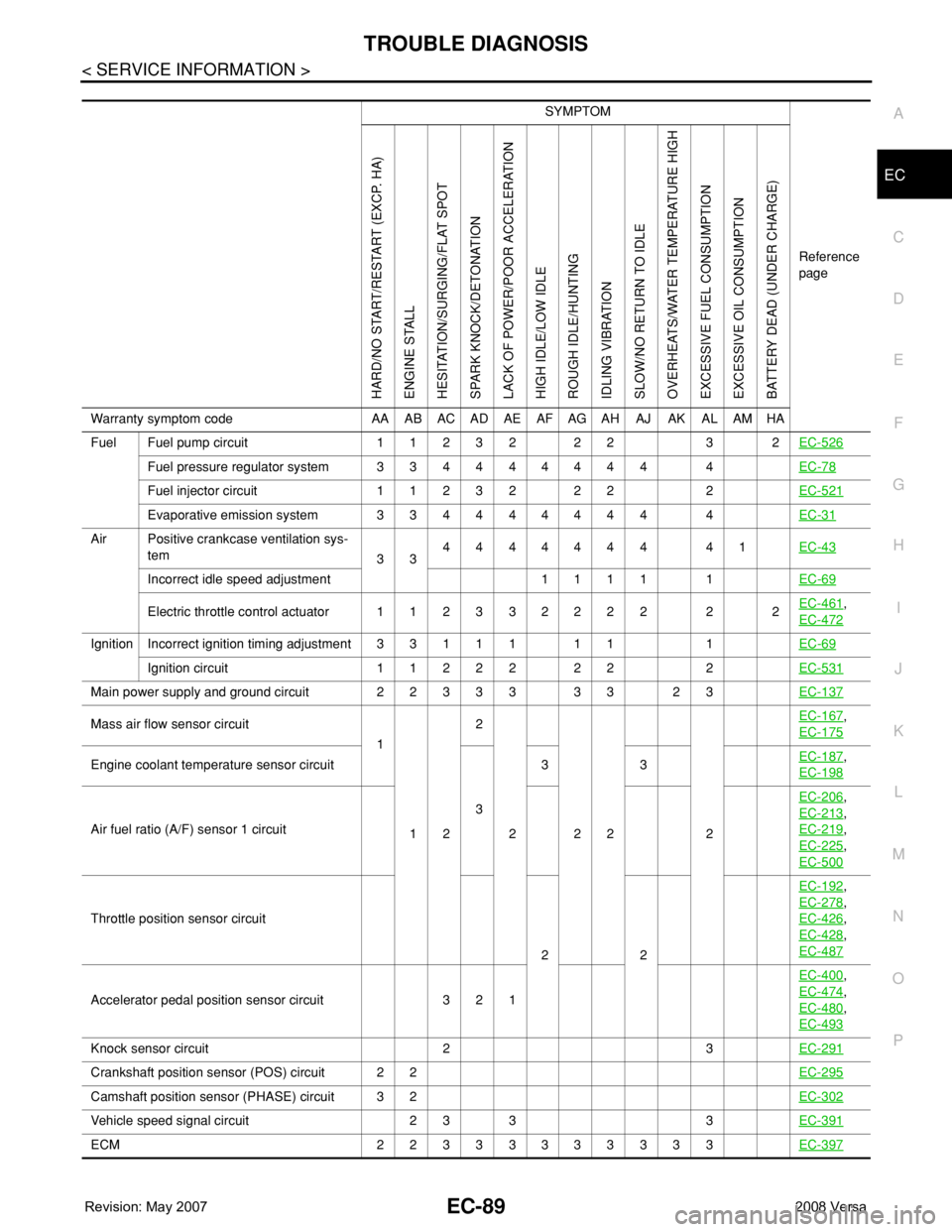
Fuel Fuel pump circuit 11232 22 3 2EC-526
Fuel pressure regulator system 334444444 4EC-78
Fuel injector circuit 11232 22 2EC-521
Evaporative emission system 334444444 4EC-31
Air Positive crankcase ventilation sys-
tem
334444444 41EC-43
Incorrect idle speed adjustment 1 1 1 1 1EC-69
Electric throttle control actuator 112332222 2 2EC-461,
EC-472
IgnitionIncorrect ignition timing adjustment33111 11 1EC-69
Ignition circuit 11222 22 2EC-531
Main power supply and ground circuit 22333 33 23EC-137
Mass air flow sensor circuit
1
122
222 2EC-167,
EC-175
Engine coolant temperature sensor circuit
333EC-187,
EC-198
Air fuel ratio (A/F) sensor 1 circuitEC-206
,
EC-213
,
EC-219
,
EC-225
,
EC-500
Throttle position sensor circuit
22EC-192
,
EC-278
,
EC-426
,
EC-428
,
EC-487
Accelerator pedal position sensor circuit 3 2 1EC-400
,
EC-474
,
EC-480
,
EC-493
Knock sensor circuit 2 3EC-291
Crankshaft position sensor (POS) circuit 2 2EC-295
Camshaft position sensor (PHASE) circuit 3 2EC-302
Vehicle speed signal circuit 2 3 3 3EC-391
ECM 22333333333EC-397
Page 1164 of 2771

EC-90
< SERVICE INFORMATION >
TROUBLE DIAGNOSIS
1 - 6: The numbers refer to the order of inspection.
(continued on next page)
SYSTEM — ENGINE MECHANICAL & OTHER
Intake valve timing control solenoid valve cir-
cuit32 13223 3EC-162
Park/neutral position (PNP) switch circuit 3 3 3 3 3EC-405
Refrigerant pressure sensor circuit 2 3 3 4EC-541
Electrical load signal circuit 3EC-519
Air conditioner circuit 223333333 3 2MTC-22
ABS actuator and electric unit (control unit) 4BRC-8
SYMPTOM
Reference
page
HARD/NO START/RESTART (EXCP. HA)
ENGINE STALL
HESITATION/SURGING/FLAT SPOT
SPARK KNOCK/DETONATION
LACK OF POWER/POOR ACCELERATION
HIGH IDLE/LOW IDLE
ROUGH IDLE/HUNTING
IDLING VIBRATION
SLOW/NO RETURN TO IDLE
OVERHEATS/WATER TEMPERATURE HIGH
EXCESSIVE FUEL CONSUMPTION
EXCESSIVE OIL CONSUMPTION
BATTERY DEAD (UNDER CHARGE)
Warranty symptom code AA AB AC AD AE AF AG AH AJ AK AL AM HA
SYMPTOM
Reference
page
HARD/NO START/RESTART (EXCP. HA)
ENGINE STALL
HESITATION/SURGING/FLAT SPOT
SPARK KNOCK/DETONATION
LACK OF POWER/POOR ACCELERATION
HIGH IDLE/LOW IDLE
ROUGH IDLE/HUNTING
IDLING VIBRATION
SLOW/NO RETURN TO IDLE
OVERHEATS/WATER TEMPERATURE HIGH
EXCESSIVE FUEL CONSUMPTION
EXCESSIVE OIL CONSUMPTION
BATTERY DEAD (UNDER CHARGE)
Warranty symptom code AA AB AC AD AE AF AG AH AJ AK AL AM HA
Fuel Fuel tank
5
5FL-9
Fuel piping 5 5 5 5 5 5EM-33
Va p o r l o c k—
Valve deposit
5 555 55 5—
Poor fuel (Heavy weight gasoline,
Low octane)—
Page 1165 of 2771
TROUBLE DIAGNOSIS
EC-91
< SERVICE INFORMATION >
C
D
E
F
G
H
I
J
K
L
MA
EC
N
P O
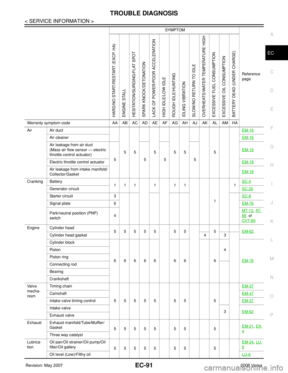
Air Air duct
55555 5EM-16
Air cleanerEM-16
Air leakage from air duct
(Mass air flow sensor — electric
throttle control actuator)
5555EM-16
Electric throttle control actuatorEM-18
Air leakage from intake manifold/
Collector/GasketEM-18
Cranking Battery
111111
11SC-4
Generator circuitSC-20
Starter circuit 3SC-8
Signal plate 6EM-76
Park/neutral position (PNP)
switch4MT-12, AT-
86 or
CVT-65
Engine Cylinder head
55555 55 5EM-62
Cylinder head gasket 4 3
Cylinder block
66666 66 64
EM-76
Piston
Piston ring
Connecting rod
Bearing
Crankshaft
Va l v e
mecha-
nismTiming chain
55555 55 5EM-37
CamshaftEM-47
Intake valve timing controlEM-37
Intake valve
3EM-62
Exhaust valve
Exhaust Exhaust manifold/Tube/Muffler/
Gasket
55555 55 5EM-21
, EX-
4Three way catalyst
Lubrica-
tionOil pan/Oil strainer/Oil pump/Oil
filter/Oil gallery
55555 55 5EM-24
, LU-
9
Oil level (Low)/Filthy oilLU-6
SYMPTOM
Reference
page
HARD/NO START/RESTART (EXCP. HA)
ENGINE STALL
HESITATION/SURGING/FLAT SPOT
SPARK KNOCK/DETONATION
LACK OF POWER/POOR ACCELERATION
HIGH IDLE/LOW IDLE
ROUGH IDLE/HUNTING
IDLING VIBRATION
SLOW/NO RETURN TO IDLE
OVERHEATS/WATER TEMPERATURE HIGH
EXCESSIVE FUEL CONSUMPTION
EXCESSIVE OIL CONSUMPTION
BATTERY DEAD (UNDER CHARGE)
Warranty symptom code AA AB AC AD AE AF AG AH AJ AK AL AM HA
Page 1166 of 2771

EC-92
< SERVICE INFORMATION >
TROUBLE DIAGNOSIS
1 - 6: The numbers refer to the order of inspection.Cooling Radiator/Hose/Radiator filler cap
55555 55 45CO-11
Thermostat 5CO-17
Water pumpCO-16
Water galleryCO-7
Cooling fan
5CO-14
Coolant level (Low)/Contaminat-
ed coolantCO-8
NVIS (NISSAN Vehicle Immobilizer System-
NATS)11BL-210
SYMPTOM
Reference
page
HARD/NO START/RESTART (EXCP. HA)
ENGINE STALL
HESITATION/SURGING/FLAT SPOT
SPARK KNOCK/DETONATION
LACK OF POWER/POOR ACCELERATION
HIGH IDLE/LOW IDLE
ROUGH IDLE/HUNTING
IDLING VIBRATION
SLOW/NO RETURN TO IDLE
OVERHEATS/WATER TEMPERATURE HIGH
EXCESSIVE FUEL CONSUMPTION
EXCESSIVE OIL CONSUMPTION
BATTERY DEAD (UNDER CHARGE)
Warranty symptom code AA AB AC AD AE AF AG AH AJ AK AL AM HA
Page 1167 of 2771
TROUBLE DIAGNOSIS
EC-93
< SERVICE INFORMATION >
C
D
E
F
G
H
I
J
K
L
MA
EC
N
P O
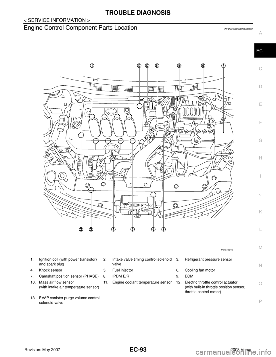
Engine Control Component Parts LocationINFOID:0000000001702590
1. Ignition coil (with power transistor)
and spark plug2. Intake valve timing control solenoid
valve3. Refrigerant pressure sensor
4. Knock sensor 5. Fuel injector 6. Cooling fan motor
7. Camshaft position sensor (PHASE) 8. IPDM E/R 9. ECM
10. Mass air flow sensor
(with intake air temperature sensor)11. Engine coolant temperature sensor 12. Electric throttle control actuator
(with built-in throttle position sensor,
throttle control motor)
13. EVAP canister purge volume control
solenoid valve
PBIB3261E
Page 1169 of 2771
TROUBLE DIAGNOSIS
EC-95
< SERVICE INFORMATION >
C
D
E
F
G
H
I
J
K
L
MA
EC
N
P O
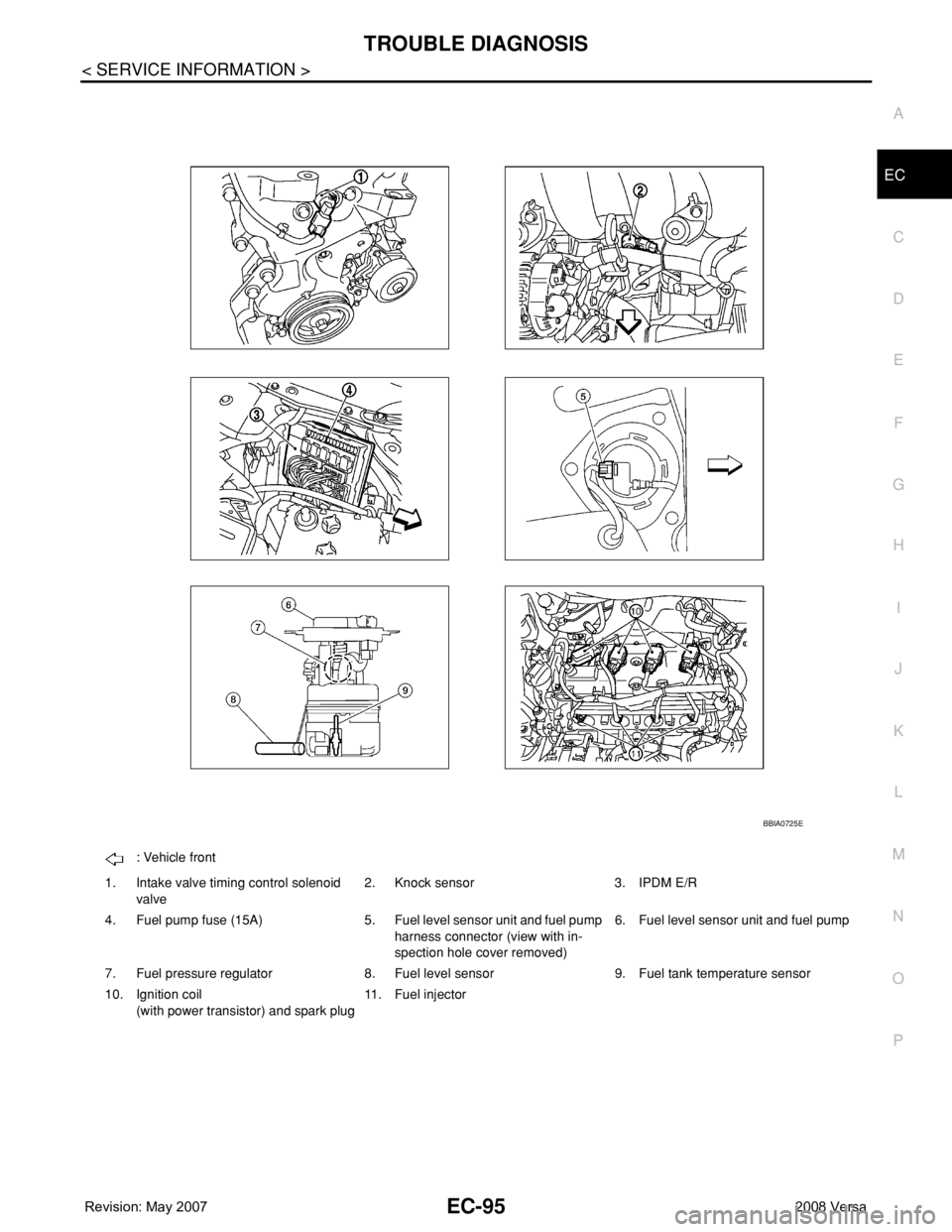
: Vehicle front
1. Intake valve timing control solenoid
valve2. Knock sensor 3. IPDM E/R
4. Fuel pump fuse (15A) 5. Fuel level sensor unit and fuel pump
harness connector (view with in-
spection hole cover removed)6. Fuel level sensor unit and fuel pump
7. Fuel pressure regulator 8. Fuel level sensor 9. Fuel tank temperature sensor
10. Ignition coil
(with power transistor) and spark plug11. Fuel injector
BBIA0725E
Page 1171 of 2771
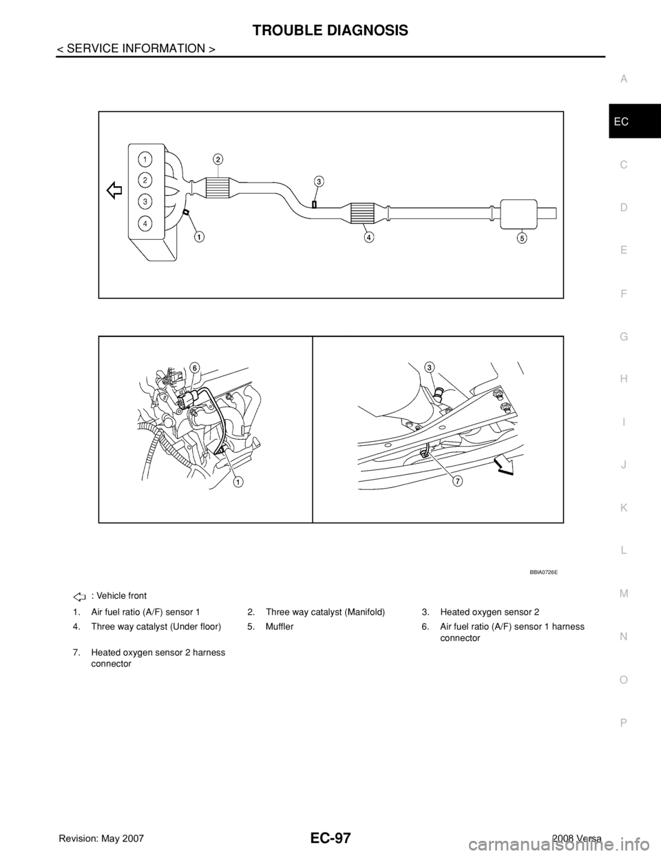
TROUBLE DIAGNOSIS
EC-97
< SERVICE INFORMATION >
C
D
E
F
G
H
I
J
K
L
MA
EC
N
P O
: Vehicle front
1. Air fuel ratio (A/F) sensor 1 2. Three way catalyst (Manifold) 3. Heated oxygen sensor 2
4. Three way catalyst (Under floor) 5. Muffler 6. Air fuel ratio (A/F) sensor 1 harness
connector
7. Heated oxygen sensor 2 harness
connector
BBIA0726E
Page 1178 of 2771
![NISSAN TIIDA 2008 Service Manual PDF EC-104
< SERVICE INFORMATION >
TROUBLE DIAGNOSIS
15 Y Throttle control motor relay[Ignition switch: OFF]BATTERY VOLTAGE
(11 - 14V)
[Ignition switch: ON]0 - 1.0V
17
18
21
22R
LG
G
SBIgnition signal No](/img/5/57399/w960_57399-1177.png "NISSAN TIIDA 2008 Service Manual PDF EC-104
< SERVICE INFORMATION >
TROUBLE DIAGNOSIS
15 Y Throttle control motor relay[Ignition switch: OFF]BATTERY VOLTAGE
(11 - 14V)
[Ignition switch: ON]0 - 1.0V
17
18
21
22R
LG
G
SBIgnition signal No")
EC-104
< SERVICE INFORMATION >
TROUBLE DIAGNOSIS
15 Y Throttle control motor relay[Ignition switch: OFF]BATTERY VOLTAGE
(11 - 14V)
[Ignition switch: ON]0 - 1.0V
17
18
21
22R
LG
G
SBIgnition signal No. 1
Ignition signal No. 2
Ignition signal No. 4
Ignition signal No. 3[Engine is running]
•Warm-up condition
• Idle speed
NOTE:
The pulse cycle changes depending on rpm
at idle.0 - 0.3V
[Engine is running]
• Warm-up condition
• Engine speed: 2,500 rpm.0.2 - 0.5V
23 GR Fuel pump relay[Ignition switch: ON]
• For 1 second after turning ignition switch
ON
[Engine is running]0 - 1.0V
[Ignition switch: ON]
• More than 1 second after turning ignition
switch ONBATTERY VOLTAGE
(11 - 14V)
25
29
30
31V
Y
O
LFuel injector No. 4
Fuel injector No. 3
Fuel injector No. 2
Fuel injector No. 1[Engine is running]
•Warm-up condition
• Idle speed
NOTE:
The pulse cycle changes depending on rpm
at idle.BATTERY VOLTAGE
(11 - 14V)
[Engine is running]
•Warm-up condition
• Engine speed: 2,000 rpmBATTERY VOLTAGE
(11 - 14V)
28 WEVAP canister vent control
valve[Ignition switch: ON]BATTERY VOLTAGE
(11 - 14V)
32 PECM relay
(Self shut-off)[Engine is running]
[Ignition switch: OFF]
• For a few seconds after turning ignition
switch OFF0 - 1.0V
[Ignition switch: OFF]
• More than a few seconds after turning igni-
tion switch OFFBATTERY VOLTAGE
(11 - 14V) TERMI-
NAL
NO.WIRE
COLORITEM CONDITION DATA (DC Voltage)
PBIA9265J
PBIA9266J
PBIB0529E
PBIA4943J
Page 1179 of 2771
![NISSAN TIIDA 2008 Service Manual PDF TROUBLE DIAGNOSIS
EC-105
< SERVICE INFORMATION >
C
D
E
F
G
H
I
J
K
L
MA
EC
N
P O
33 LG Throttle position sensor 1[Ignition switch: ON]
• Engine stopped
• Shift lever: D (A/T, CVT), 1st (M/T)
• A](/img/5/57399/w960_57399-1178.png "NISSAN TIIDA 2008 Service Manual PDF TROUBLE DIAGNOSIS
EC-105
< SERVICE INFORMATION >
C
D
E
F
G
H
I
J
K
L
MA
EC
N
P O
33 LG Throttle position sensor 1[Ignition switch: ON]
• Engine stopped
• Shift lever: D (A/T, CVT), 1st (M/T)
• A")
TROUBLE DIAGNOSIS
EC-105
< SERVICE INFORMATION >
C
D
E
F
G
H
I
J
K
L
MA
EC
N
P O
33 LG Throttle position sensor 1[Ignition switch: ON]
• Engine stopped
• Shift lever: D (A/T, CVT), 1st (M/T)
• Accelerator pedal: Fully releasedMore than 0.36V
[Ignition switch: ON]
• Engine stopped
• Shift lever: D (A/T, CVT), 1st (M/T)
• Accelerator pedal: Fully depressedLess than 4.75V
34 O Throttle position sensor 2[Ignition switch: ON]
• Engine stopped
• Shift lever: D (A/T, CVT), 1st (M/T)
• Accelerator pedal: Fully releasedLess than 4.75V
[Ignition switch: ON]
• Engine stopped
• Shift lever: D (A/T, CVT), 1st (M/T)
• Accelerator pedal: Fully depressedMore than 0.36V
36 YSensor ground
(Throttle position sensor)[Engine is running]
•Warm-up condition
• Idle speedApproximately 0V
37 W Knock sensor[Engine is running]
• Idle speedApproximately 2.5V
38 PEngine coolant temperature
sensor[Engine is running]Approximately 0 - 4.8V
Output voltage varies with en-
gine coolant temperature.
40 —Sensor ground
(Knock sensor)[Engine is running]
•Warm-up condition
• Idle speedApproximately 0V
41 GR Refrigerant pressure sensor[Engine is running]
•Warm-up condition
• Both A/C switch and blower fan switch: ON
(Compressor operates.)1.0 - 4.0V
42 VEVAP control system pres-
sure sensor[Ignition switch: ON]Approximately 1.8 - 4.8V
43 PFuel tank temperature sen-
sor[Engine is running]Approximately 0 - 4.8V
Output voltage varies with fuel
tank temperature
44 BSensor ground
(Engine coolant temperature
sensor)[Engine is running]
•Warm-up condition
• Idle speedApproximately 0V
45 G Mass air flow sensor[Engine is running]
•Warm-up condition
• Idle speed0.8 - 1.1V
[Engine is running]
•Warm-up condition
• Engine speed: 2,500 rpm1.4 - 1.7V
46 VIntake air temperature
sensor[Engine is running]Approximately 0 - 4.8V
Output voltage varies with intake
air temperature.
48 BRSensor ground
(Refrigerant pressure sen-
sor)[Engine is running]
•Warm-up condition
• Idle speed
Approximately 0V
49 W A/F sensor 1[Engine is running]
•Warm-up condition
• Engine speed: 2,000 rpmApproximately 1.8V
Output voltage varies with air fuel
ratio. TERMI-
NAL
NO.WIRE
COLORITEM CONDITION DATA (DC Voltage)
Page 1183 of 2771

TROUBLE DIAGNOSIS
EC-109
< SERVICE INFORMATION >
C
D
E
F
G
H
I
J
K
L
MA
EC
N
P O
CONSULT-II Function (ENGINE)INFOID:0000000001702595
FUNCTION
*: The following emission-related diagnostic information is cleared when the ECM memory is erased.
• Diagnostic trouble codes
• 1st trip diagnostic trouble codes
• Freeze frame data
• 1st trip freeze frame data
• System readiness test (SRT) codes
•Test values
ENGINE CONTROL COMPONENT PARTS/CONTROL SYSTEMS APPLICATION
Diagnostic test mode Function
Work supportThis mode enables a technician to adjust some devices faster and more accurately by following the in-
dications on the CONSULT-II unit.
Self-diagnostic resultsSelf-diagnostic results such as 1st trip DTC, DTCs and 1st trip freeze frame data or freeze frame data
can be read and erased quickly.*
Data monitor Input/Output data in the ECM can be read.
Data monitor (SPEC)Input/Output of the specification for Basic fuel schedule, AFM, A/F feedback control value and the other
data monitor items can be read.
CAN diagnostic support mon-
itorThe results of transmit/receive diagnosis of CAN communication can be read.
Active testDiagnostic Test Mode in which CONSULT-II drives some actuators apart from the ECMs and also shifts
some parameters in a specified range.
Function test This mode is used to inform customers when their vehicle condition requires periodic maintenance.
DTC & SRT confirmation The status of system monitoring tests and the self-diagnosis status/result can be confirmed.
ECM part number ECM part number can be read.