fuel NISSAN TIIDA 2008 Service Owners Manual
[x] Cancel search | Manufacturer: NISSAN, Model Year: 2008, Model line: TIIDA, Model: NISSAN TIIDA 2008Pages: 2771, PDF Size: 60.61 MB
Page 1195 of 2771
TROUBLE DIAGNOSIS
EC-121
< SERVICE INFORMATION >
C
D
E
F
G
H
I
J
K
L
MA
EC
N
P O
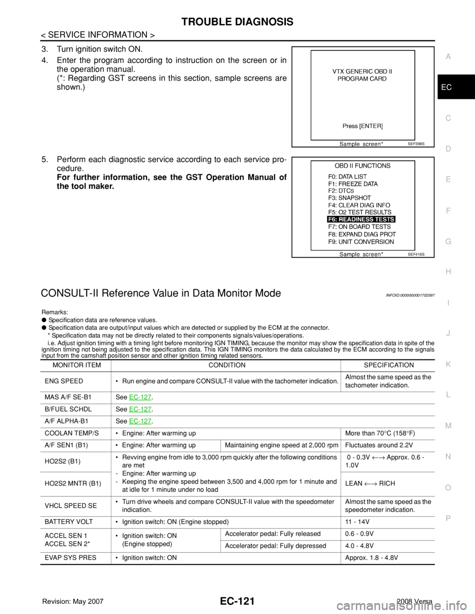
3. Turn ignition switch ON.
4. Enter the program according to instruction on the screen or in
the operation manual.
(*: Regarding GST screens in this section, sample screens are
shown.)
5. Perform each diagnostic service according to each service pro-
cedure.
For further information, see the GST Operation Manual of
the tool maker.
CONSULT-II Reference Value in Data Monitor ModeINFOID:0000000001702597
Remarks:
● Specification data are reference values.
● Specification data are output/input values which are detected or supplied by the ECM at the connector.
* Specification data may not be directly related to their components signals/values/operations.
i.e. Adjust ignition timing with a timing light before monitoring IGN TIMING, because the monitor may show the specification data in spite of the
ignition timing not being adjusted to the specification data. This IGN TIMING monitors the data calculated by the ECM according to the signals
input from the camshaft position sensor and other ignition timing related sensors.
SEF398S
SEF416S
MONITOR ITEM CONDITION SPECIFICATION
ENG SPEED • Run engine and compare CONSULT-II value with the tachometer indication.Almost the same speed as the
tachometer indication.
MAS A/F SE-B1 See EC-127
.
B/FUEL SCHDL See EC-127
.
A/F ALPHA-B1 See EC-127
.
COOLAN TEMP/S • Engine: After warming up More than 70°C (158°F)
A/F SEN1 (B1) • Engine: After warming up Maintaining engine speed at 2,000 rpm Fluctuates around 2.2V
HO2S2 (B1)• Revving engine from idle to 3,000 rpm quickly after the following conditions
are met
- Engine: After warming up
- Keeping the engine speed between 3,500 and 4,000 rpm for 1 minute and
at idle for 1 minute under no load 0 - 0.3V ←→ Approx. 0.6 -
1.0V
HO2S2 MNTR (B1)LEAN ←→ RICH
VHCL SPEED SE• Turn drive wheels and compare CONSULT-II value with the speedometer
indication.Almost the same speed as the
speedometer indication.
BATTERY VOLT • Ignition switch: ON (Engine stopped) 11 - 14V
ACCEL SEN 1
ACCEL SEN 2*• Ignition switch: ON
(Engine stopped)Accelerator pedal: Fully released 0.6 - 0.9V
Accelerator pedal: Fully depressed 4.0 - 4.8V
EVAP SYS PRES • Ignition switch: ON Approx. 1.8 - 4.8V
Page 1197 of 2771

TROUBLE DIAGNOSIS
EC-123
< SERVICE INFORMATION >
C
D
E
F
G
H
I
J
K
L
MA
EC
N
P O
INT/V SOL (B1)• Engine: After warming up
• Air conditioner switch: OFF
• Shift lever: P or N (A/T, CVT),
Neutral (M/T)
•No loadIdle 0% - 2%
When revving engine up to 2,000 rpm
quicklyApprox. 0% - 90%
AIR COND RLY• Engine: After warming up, idle the
engineAir conditioner switch: OFF OFF
Air conditioner switch: ON
(Compressor operates)ON
FUEL PUMP RLY• For 1 second after turning ignition switch ON
• Engine running or crankingON
• Except above conditions OFF
VENT CONT/V • Ignition switch: ON OFF
THRTL RELAY • Ignition switch: ON ON
COOLING FAN• Engine: After warming up, idle the
engine
• Air conditioner switch: OFFEngine coolant temperature: 97°C
(207°F) or lessOFF
Engine coolant temperature: Between
98°C (208°F) and 99°C (210°F)LOW
Engine coolant temperature: 100°C
(212°F) or moreHIGH
HO2S2 HTR (B1)• Below 3,600 rpm after the following conditions are met.
- Engine: After warming up
- Keeping the engine speed between 3,500 and 4,000 rpm for 1 minute and
at idle for 1 minute under no loadON
• Engine speed: Above 3,600 rpm OFF
I/P PULLY SPD • Vehicle speed: More than 20 km/h (12 MPH)Almost the same speed as the
tachometer indication
VEHICLE SPEED• Turn drive wheels and compare CONSULT-II value with the speedometer
indication.Almost the same speed as the
speedometer indication
TRVL AFTER MIL • Ignition switch: ONVehicle has traveled after MIL has
turned ON.0 - 65,535 km
(0 - 40,723 mile)
A/F S1 HTR (B1)• Engine: After warming up, idle the engine
(More than 140 seconds after starting engine.)4 - 100%
AC PRESS SEN• Engine: Idle
• Air conditioner switch: ON (Compressor operates)1.0 - 4.0V
VHCL SPEED SE• Turn drive wheels and compare speedometer indication with the CONSULT-
II value.Almost the same speed as the
speedometer indication
SET VHCL SPD • Engine: Running ASCD: OperatingThe preset vehicle speed is
displayed.
MAIN SW • Ignition switch: ONMAIN switch: Pressed ON
MAIN switch: Released OFF
CANCEL SW • Ignition switch: ONCANCEL switch: Pressed ON
CANCEL switch: Released OFF
RESUME/ACC SW • Ignition switch: ONRESUME/ACCELERATE switch:
PressedON
RESUME/ACCELERATE switch: Re-
leased
OFF
SET SW • Ignition switch: ONSET/COAST switch: Pressed ON
SET/COAST switch: Released OFF MONITOR ITEM CONDITION SPECIFICATION
Page 1201 of 2771
TROUBLE DIAGNOSIS - SPECIFICATION VALUE
EC-127
< SERVICE INFORMATION >
C
D
E
F
G
H
I
J
K
L
MA
EC
N
P O
TROUBLE DIAGNOSIS - SPECIFICATION VALUE
DescriptionINFOID:0000000001702599
The specification (SP) value indicates the tolerance of the value that is displayed in “DATA MONITOR (SPEC)”
mode of CONSULT-II during normal operation of the Engine Control System. When the value in “DATA MONI-
TOR (SPEC)” mode is within the SP value, the Engine Control System is confirmed OK. When the value in
“DATA MONITOR (SPEC)” mode is NOT within the SP value, the Engine Control System may have one or
more malfunctions.
The SP value is used to detect malfunctions that may affect the Engine Control System, but will not light the
MIL.
The SP value will be displayed for the following three items:
• B/FUEL SCHDL (The fuel injection pulse width programmed into ECM prior to any learned on board correc-
tion)
• A/F ALPHA-B1 (The mean value of air-fuel ratio feedback correction factor per cycle)
• MAS A/F SE-B1 (The signal voltage of the mass air flow sensor)
Testing ConditionINFOID:0000000001702600
• Vehicle driven distance: More than 5,000 km (3,107 miles)
• Barometric pressure: 98.3 - 104.3 kPa (1.003 - 1.064 kg/cm
2, 14.25 - 15.12 psi)
• Atmospheric temperature: 20 - 30°C (68 - 86°F)
• Engine coolant temperature: 75 - 95°C (167 - 203°F)
• Transmission: Warmed-up
- A/T and CVT models: After the engine is warmed up to normal operating temperature, drive vehicle until
“FLUID TEMP SE” (A/T or CVT) fluid temperature sensor signal) indicates more than 60°C (140°F).
- M/T models: After the engine is warmed up to normal operating temperature, drive vehicle for 5 minutes.
• Electrical load: Not applied
- Rear window defogger switch, air conditioner switch, lighting switch are OFF. Steering wheel is straight
ahead.
• Engine speed: Idle
Inspection ProcedureINFOID:0000000001702601
NOTE:
Perform “DATA MONITOR (SPEC)” mode in maximum scale display.
1. Perform EC-69, "
Basic Inspection".
2. Confirm that the testing conditions indicated above are met.
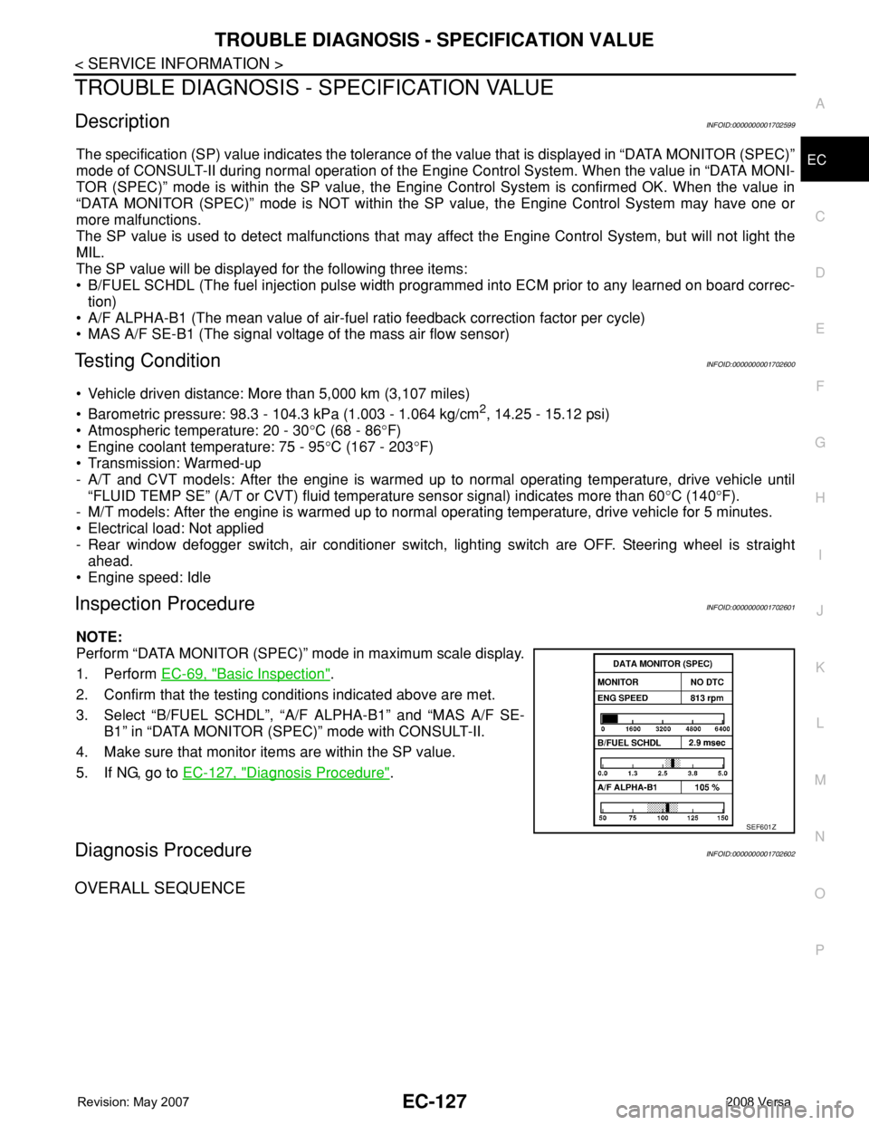
3. Select “B/FUEL SCHDL”, “A/F ALPHA-B1” and “MAS A/F SE-
B1” in “DATA MONITOR (SPEC)” mode with CONSULT-II.
4. Make sure that monitor items are within the SP value.
5. If NG, go to EC-127, "
Diagnosis Procedure".
Diagnosis ProcedureINFOID:0000000001702602
OVERALL SEQUENCE
SEF601Z
Page 1204 of 2771
EC-130
< SERVICE INFORMATION >
TROUBLE DIAGNOSIS - SPECIFICATION VALUE
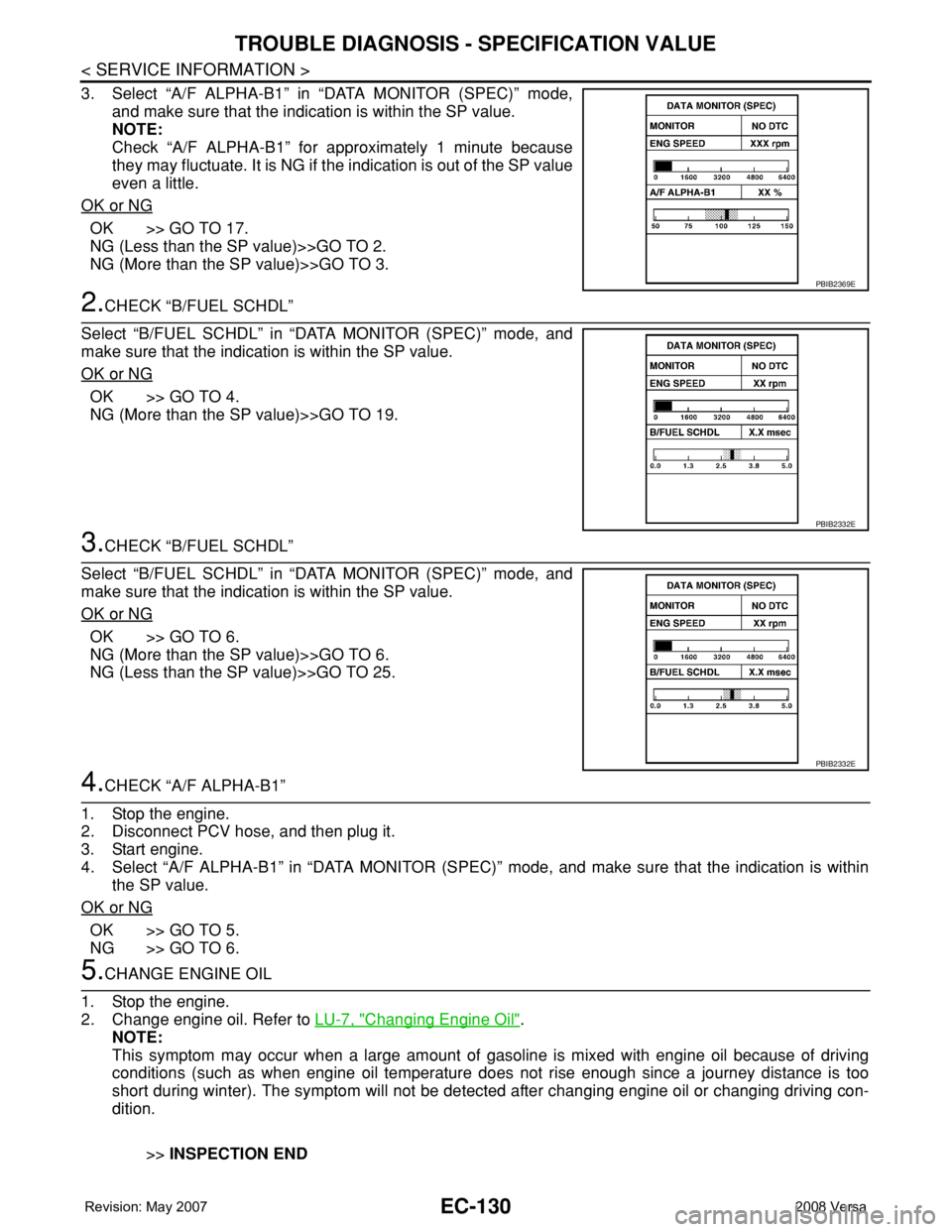
3. Select “A/F ALPHA-B1” in “DATA MONITOR (SPEC)” mode,
and make sure that the indication is within the SP value.
NOTE:
Check “A/F ALPHA-B1” for approximately 1 minute because
they may fluctuate. It is NG if the indication is out of the SP value
even a little.
OK or NG
OK >> GO TO 17.
NG (Less than the SP value)>>GO TO 2.
NG (More than the SP value)>>GO TO 3.
2.CHECK “B/FUEL SCHDL”
Select “B/FUEL SCHDL” in “DATA MONITOR (SPEC)” mode, and
make sure that the indication is within the SP value.
OK or NG
OK >> GO TO 4.
NG (More than the SP value)>>GO TO 19.
3.CHECK “B/FUEL SCHDL”
Select “B/FUEL SCHDL” in “DATA MONITOR (SPEC)” mode, and
make sure that the indication is within the SP value.
OK or NG
OK >> GO TO 6.
NG (More than the SP value)>>GO TO 6.
NG (Less than the SP value)>>GO TO 25.
4.CHECK “A/F ALPHA-B1”
1. Stop the engine.
2. Disconnect PCV hose, and then plug it.
3. Start engine.
4. Select “A/F ALPHA-B1” in “DATA MONITOR (SPEC)” mode, and make sure that the indication is within
the SP value.
OK or NG
OK >> GO TO 5.
NG >> GO TO 6.
5.CHANGE ENGINE OIL
1. Stop the engine.
2. Change engine oil. Refer to LU-7, "
Changing Engine Oil".
NOTE:
This symptom may occur when a large amount of gasoline is mixed with engine oil because of driving
conditions (such as when engine oil temperature does not rise enough since a journey distance is too
short during winter). The symptom will not be detected after changing engine oil or changing driving con-
dition.
>>INSPECTION END
PBIB2369E
PBIB2332E
PBIB2332E
Page 1205 of 2771
TROUBLE DIAGNOSIS - SPECIFICATION VALUE
EC-131
< SERVICE INFORMATION >
C
D
E
F
G
H
I
J
K
L
MA
EC
N
P O
6.CHECK FUEL PRESSURE
Check fuel pressure. (Refer to EC-78, "
Fuel Pressure Check".)
OK or NG
OK >> GO TO 9.
NG (Fuel pressure is too high)>>Replace fuel pressure regulator, refer to EC-78, "
Fuel Pressure Check". GO
TO 8.
NG (Fuel pressure is too low)>>GO TO 7.
7.DETECT MALFUNCTIONING PART
1. Check the following.
- Clogged and bent fuel hose and fuel tube
- Clogged fuel filter
- Fuel pump and its circuit (Refer to EC-526
.)
2. If NG, repair or replace the malfunctioning part. (Refer to EC-78, "
Fuel Pressure Check".)
If OK, replace fuel pressure regulator.
>> GO TO 8.
8.CHECK “A/F ALPHA-B1”
1. Start engine.
2. Select “A/F ALPHA-B1” in “DATA MONITOR (SPEC)” mode, and make sure that the indication is within
the SP value.
OK or NG
OK >>INSPECTION END
NG >> GO TO 9.
9.PERFORM POWER BALANCE TEST
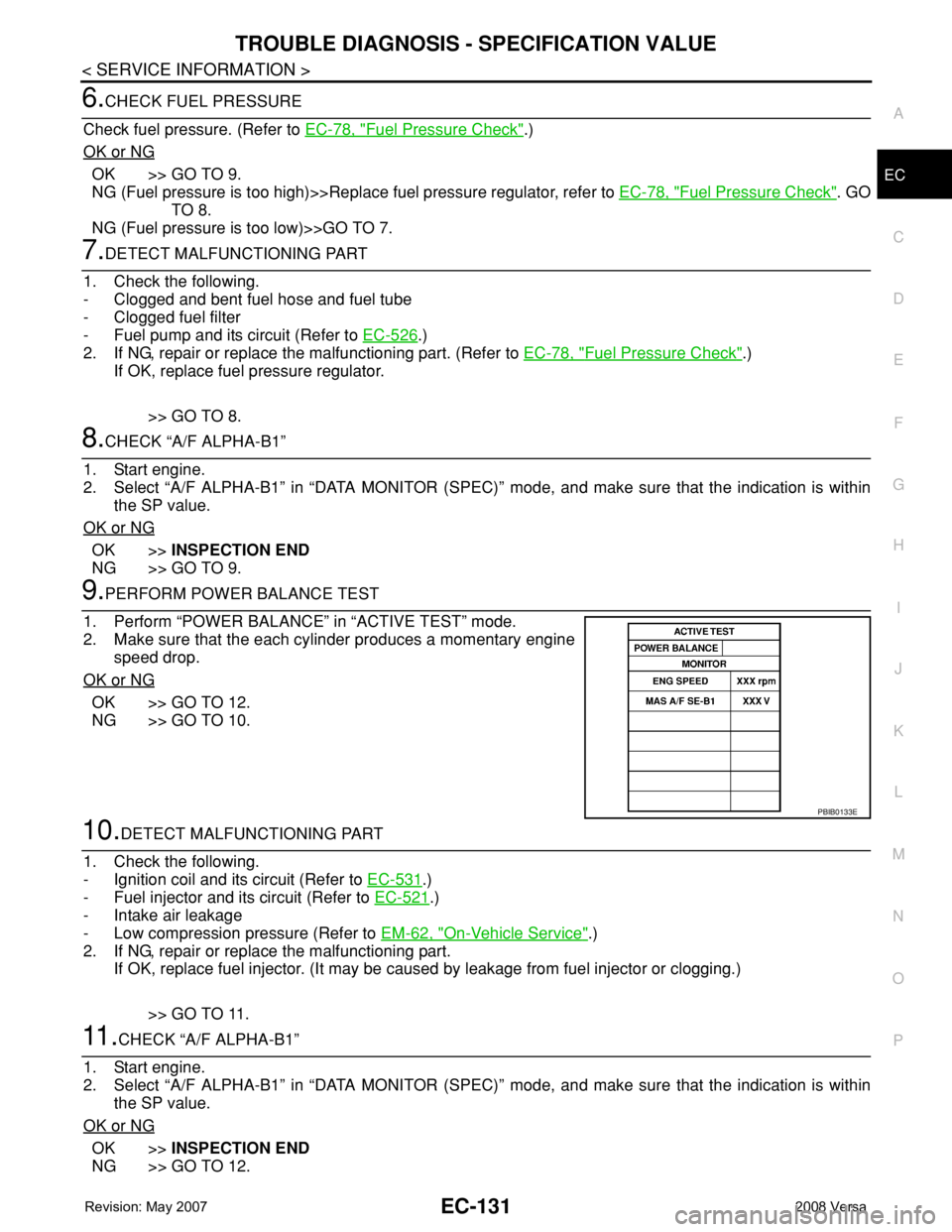
1. Perform “POWER BALANCE” in “ACTIVE TEST” mode.
2. Make sure that the each cylinder produces a momentary engine
speed drop.
OK or NG
OK >> GO TO 12.
NG >> GO TO 10.
10.DETECT MALFUNCTIONING PART
1. Check the following.
- Ignition coil and its circuit (Refer to EC-531
.)
- Fuel injector and its circuit (Refer to EC-521
.)
- Intake air leakage
- Low compression pressure (Refer to EM-62, "
On-Vehicle Service".)
2. If NG, repair or replace the malfunctioning part.
If OK, replace fuel injector. (It may be caused by leakage from fuel injector or clogging.)
>> GO TO 11.
11 .CHECK “A/F ALPHA-B1”
1. Start engine.
2. Select “A/F ALPHA-B1” in “DATA MONITOR (SPEC)” mode, and make sure that the indication is within
the SP value.
OK or NG
OK >>INSPECTION END
NG >> GO TO 12.
PBIB0133E
Page 1206 of 2771
EC-132
< SERVICE INFORMATION >
TROUBLE DIAGNOSIS - SPECIFICATION VALUE
12.CHECK A/F SENSOR 1 FUNCTION
Perform all DTC Confirmation Procedure related with A/F sensor 1.
• For DTC P0130, refer to EC-206, "
DTC Confirmation Procedure".
• For DTC P0131, refer to EC-213, "
DTC Confirmation Procedure".
• For DTC P0132, refer to EC-219, "
DTC Confirmation Procedure".
• For DTC P0133, refer to EC-225, "
DTC Confirmation Procedure".
• For DTC P2A00, refer to EC-500, "
DTC Confirmation Procedure".
OK or NG
OK >> GO TO 15.
NG >> GO TO 13.
13.CHECK A/F SENSOR 1 CIRCUIT
Perform Diagnostic Procedure according to corresponding DTC.
>> GO TO 14.
14.CHECK “A/F ALPHA-B1”
1. Start engine.
2. Select “A/F ALPHA-B1” in “DATA MONITOR (SPEC)” mode, and make sure that the indication is within
the SP value.
OK or NG
OK >>INSPECTION END
NG >> GO TO 15.
15.DISCONNECT AND RECONNECT ECM HARNESS CONNECTOR
1. Stop the engine.
2. Disconnect ECM harness connector. Check pin terminal and connector for damage, and then reconnect it.
>> GO TO 16.
16.CHECK “A/F ALPHA-B1”
1. Start engine.
2. Select “A/F ALPHA-B1” in “DATA MONITOR (SPEC)” mode, and make sure that the indication is within
the SP value.
OK or NG
OK >>INSPECTION END
NG >> Detect malfunctioning part according to EC-88, "
Symptom Matrix Chart".
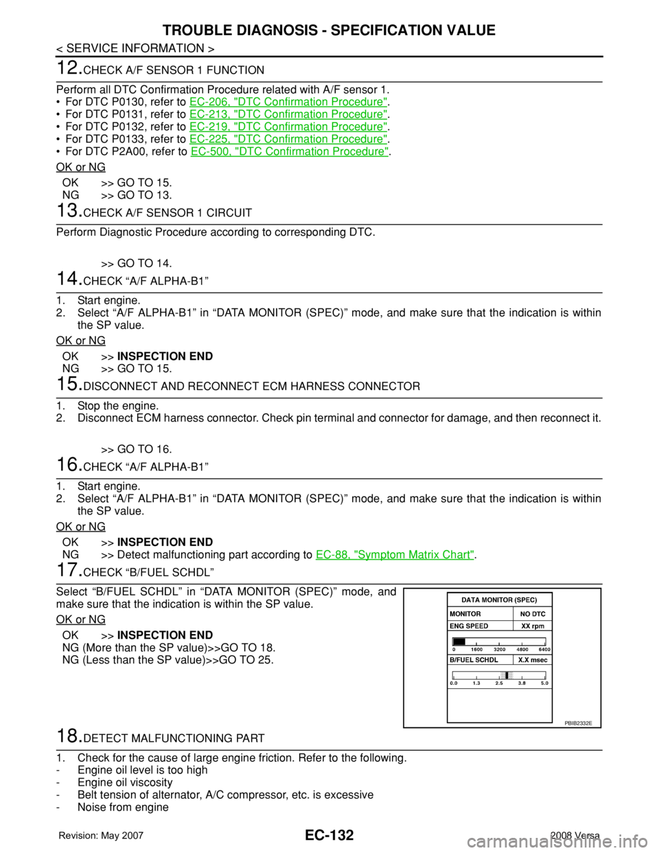
17.CHECK “B/FUEL SCHDL”
Select “B/FUEL SCHDL” in “DATA MONITOR (SPEC)” mode, and
make sure that the indication is within the SP value.
OK or NG
OK >>INSPECTION END
NG (More than the SP value)>>GO TO 18.
NG (Less than the SP value)>>GO TO 25.
18.DETECT MALFUNCTIONING PART
1. Check for the cause of large engine friction. Refer to the following.
- Engine oil level is too high
- Engine oil viscosity
- Belt tension of alternator, A/C compressor, etc. is excessive
- Noise from engine
PBIB2332E
Page 1207 of 2771
TROUBLE DIAGNOSIS - SPECIFICATION VALUE
EC-133
< SERVICE INFORMATION >
C
D
E
F
G
H
I
J
K
L
MA
EC
N
P O
- Noise from transmission, etc.
2. Check for the cause of insufficient combustion. Refer to the following.
- Valve clearance malfunction
- Intake valve timing control function malfunction
- Camshaft sprocket installation malfunction, etc.
>> Repair or replace malfunctioning part, and then GO TO 30.
19.CHECK INTAKE SYSTEM
Check for the cause of uneven air flow through mass air flow sensor. Refer to the following.
• Crushed air ducts
• Malfunctioning seal of air cleaner element
• Uneven dirt of air cleaner element
• Improper specification of intake air system
OK or NG
OK >> GO TO 21.
NG >> Repair or replace malfunctioning part, and then GO TO 20.
20.CHECK “A/F ALPHA-B1” AND “B/FUEL SCHDL”
Select “A/F ALPHA-B1” and “B/FUEL SCHDL” in “DATA MONITOR (SPEC)” mode, and make sure that the
each indication is within the SP value.
OK or NG
OK >>INSPECTION END
NG (“B/FUEL SCHDL” is more, “A/F ALPHA-B1” is less than the SP value)>>GO TO 21.
21.DISCONNECT AND RECONNECT MASS AIR FLOW SENSOR HARNESS CONNECTOR
1. Stop the engine.
2. Disconnect mass air flow sensor harness connector. Check pin terminal and connector for damage and
then reconnect it again.
>> GO TO 22.
22.CHECK “A/F ALPHA-B1”
1. Start engine.
2. Select “A/F ALPHA-B1” in “DATA MONITOR (SPEC)” mode, and make sure that the indication is within
the SP value.
OK or NG
OK >> 1. Detect malfunctioning part of mass air flow sensor circuit and repair it. Refer to EC-167.
2. GO TO 29.
NG >> GO TO 23.
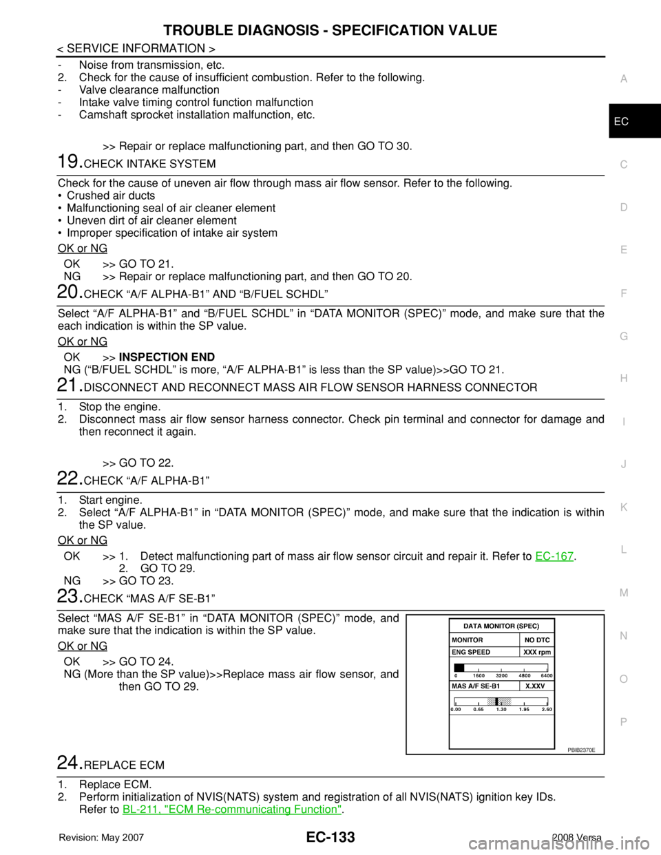
23.CHECK “MAS A/F SE-B1”
Select “MAS A/F SE-B1” in “DATA MONITOR (SPEC)” mode, and
make sure that the indication is within the SP value.
OK or NG
OK >> GO TO 24.
NG (More than the SP value)>>Replace mass air flow sensor, and
then GO TO 29.
24.REPLACE ECM
1. Replace ECM.
2. Perform initialization of NVIS(NATS) system and registration of all NVIS(NATS) ignition key IDs.
Refer to BL-211, "
ECM Re-communicating Function".
PBIB2370E
Page 1208 of 2771
EC-134
< SERVICE INFORMATION >
TROUBLE DIAGNOSIS - SPECIFICATION VALUE
3. Perform EC-75, "VIN Registration".
4. Perform EC-76, "
Accelerator Pedal Released Position Learning".
5. Perform EC-76, "
Throttle Valve Closed Position Learning".
6. Perform EC-76, "
Idle Air Volume Learning".
>> GO TO 29.
25.CHECK INTAKE SYSTEM
Check for the cause of uneven air flow through mass air flow sensor. Refer to the following.
• Crushed air ducts
• Malfunctioning seal of air cleaner element
• Uneven dirt of air cleaner element
• Improper specification of intake air system
OK or NG
OK >> GO TO 27.
NG >> Repair or replace malfunctioning part, and then GO TO 26.
26.CHECK “B/FUEL SCHDL”
Select “B/FUEL SCHDL” in “DATA MONITOR (SPEC)” mode, and make sure that the indication is within the
SP value.
OK or NG
OK >>INSPECTION END
NG (Less than the SP value)>>GO TO 27.
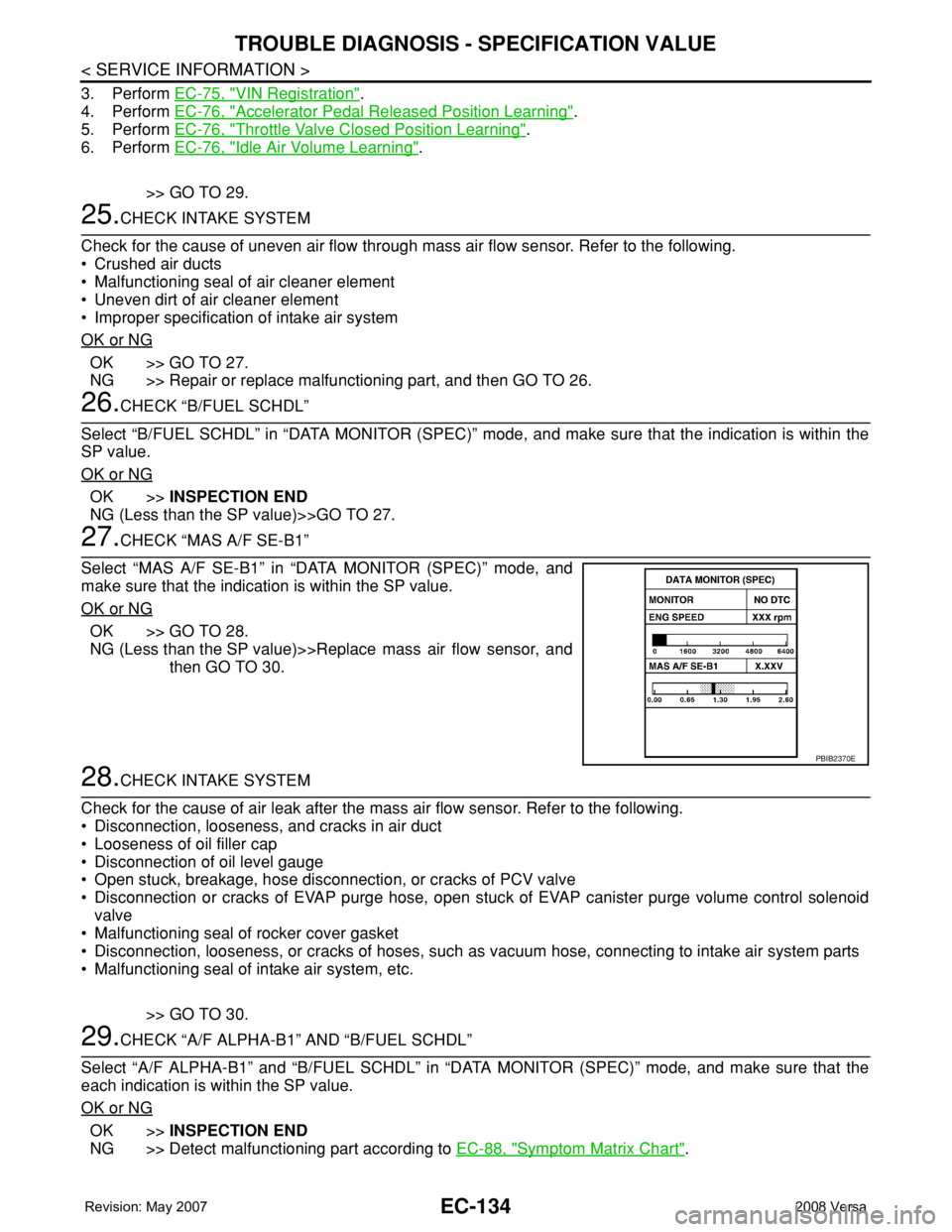
27.CHECK “MAS A/F SE-B1”
Select “MAS A/F SE-B1” in “DATA MONITOR (SPEC)” mode, and
make sure that the indication is within the SP value.
OK or NG
OK >> GO TO 28.
NG (Less than the SP value)>>Replace mass air flow sensor, and
then GO TO 30.
28.CHECK INTAKE SYSTEM
Check for the cause of air leak after the mass air flow sensor. Refer to the following.
• Disconnection, looseness, and cracks in air duct
• Looseness of oil filler cap
• Disconnection of oil level gauge
• Open stuck, breakage, hose disconnection, or cracks of PCV valve
• Disconnection or cracks of EVAP purge hose, open stuck of EVAP canister purge volume control solenoid
valve
• Malfunctioning seal of rocker cover gasket
• Disconnection, looseness, or cracks of hoses, such as vacuum hose, connecting to intake air system parts
• Malfunctioning seal of intake air system, etc.
>> GO TO 30.
29.CHECK “A/F ALPHA-B1” AND “B/FUEL SCHDL”
Select “A/F ALPHA-B1” and “B/FUEL SCHDL” in “DATA MONITOR (SPEC)” mode, and make sure that the
each indication is within the SP value.
OK or NG
OK >>INSPECTION END
NG >> Detect malfunctioning part according to EC-88, "
Symptom Matrix Chart".
PBIB2370E
Page 1209 of 2771

TROUBLE DIAGNOSIS - SPECIFICATION VALUE
EC-135
< SERVICE INFORMATION >
C
D
E
F
G
H
I
J
K
L
MA
EC
N
P O
30.CHECK “B/FUEL SCHDL”
Select “B/FUEL SCHDL” in “DATA MONITOR (SPEC)” mode, and then make sure that the indication is within
the SP value.
OK or NG
OK >>INSPECTION END
NG >> Detect malfunctioning part according to EC-88, "
Symptom Matrix Chart".
Page 1222 of 2771
EC-148
< SERVICE INFORMATION >
DTC P0011 IVT CONTROL
On Board Diagnosis Logic
INFOID:0000000001702619
FAIL-SAFE MODE
ECM enters in fail-safe mode when the malfunction is detected.
DTC Confirmation ProcedureINFOID:0000000001702620
CAUTION:
Always drive at a safe speed.
NOTE:
•If DTC P0011 is displayed with DTC P0075, first perform trouble diagnosis for DTC P0075.
See EC-162
.
• If DTC Confirmation Procedure has been previously conducted, always turn ignition switch OFF and wait at
least 10 seconds before conducting the next test.
TESTING CONDITION:
Before performing the following procedure, confirm that battery voltage is between 10V and 16V at
idle.
WITH CONSULT-II
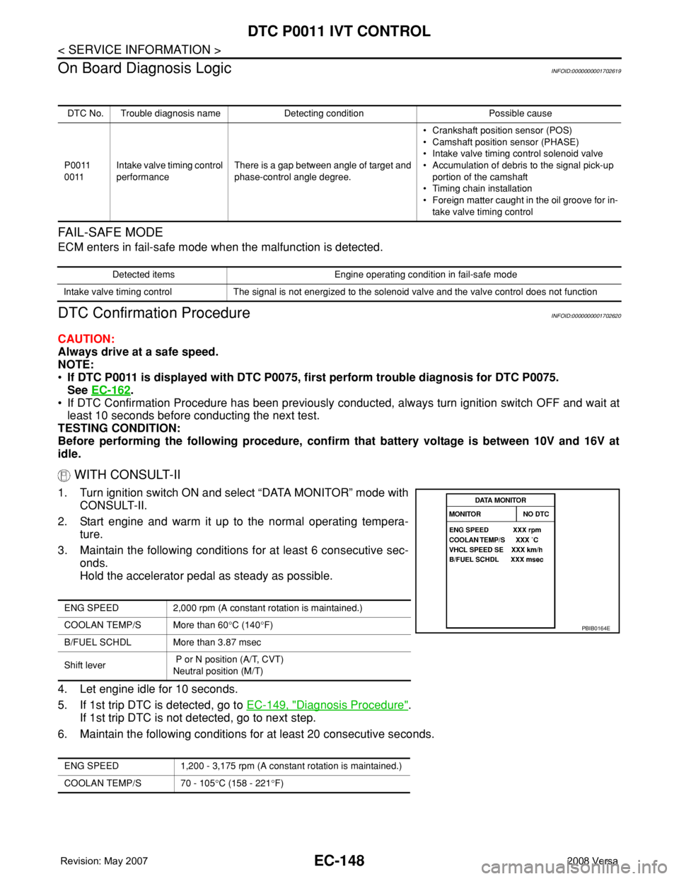
1. Turn ignition switch ON and select “DATA MONITOR” mode with
CONSULT-II.
2. Start engine and warm it up to the normal operating tempera-
ture.
3. Maintain the following conditions for at least 6 consecutive sec-
onds.
Hold the accelerator pedal as steady as possible.
4. Let engine idle for 10 seconds.
5. If 1st trip DTC is detected, go to EC-149, "
Diagnosis Procedure".
If 1st trip DTC is not detected, go to next step.
6. Maintain the following conditions for at least 20 consecutive seconds.
DTC No. Trouble diagnosis name Detecting condition Possible cause
P0011
0011Intake valve timing control
performanceThere is a gap between angle of target and
phase-control angle degree.• Crankshaft position sensor (POS)
• Camshaft position sensor (PHASE)
• Intake valve timing control solenoid valve
• Accumulation of debris to the signal pick-up
portion of the camshaft
• Timing chain installation
• Foreign matter caught in the oil groove for in-
take valve timing control
Detected items Engine operating condition in fail-safe mode
Intake valve timing control The signal is not energized to the solenoid valve and the valve control does not function
ENG SPEED 2,000 rpm (A constant rotation is maintained.)
COOLAN TEMP/S More than 60°C (140°F)
B/FUEL SCHDL More than 3.87 msec
Shift lever P or N position (A/T, CVT)
Neutral position (M/T)
ENG SPEED 1,200 - 3,175 rpm (A constant rotation is maintained.)
COOLAN TEMP/S 70 - 105°C (158 - 221°F)
PBIB0164E