NISSAN TIIDA 2008 Service Repair Manual
TIIDA 2008
NISSAN
NISSAN
https://www.carmanualsonline.info/img/5/57399/w960_57399-0.png
NISSAN TIIDA 2008 Service Repair Manual
Trending: battery terminal, key fob battery, Automatic transmission change, spare wheel, start stop button, Electric, wheel cylinders
Page 1661 of 2771
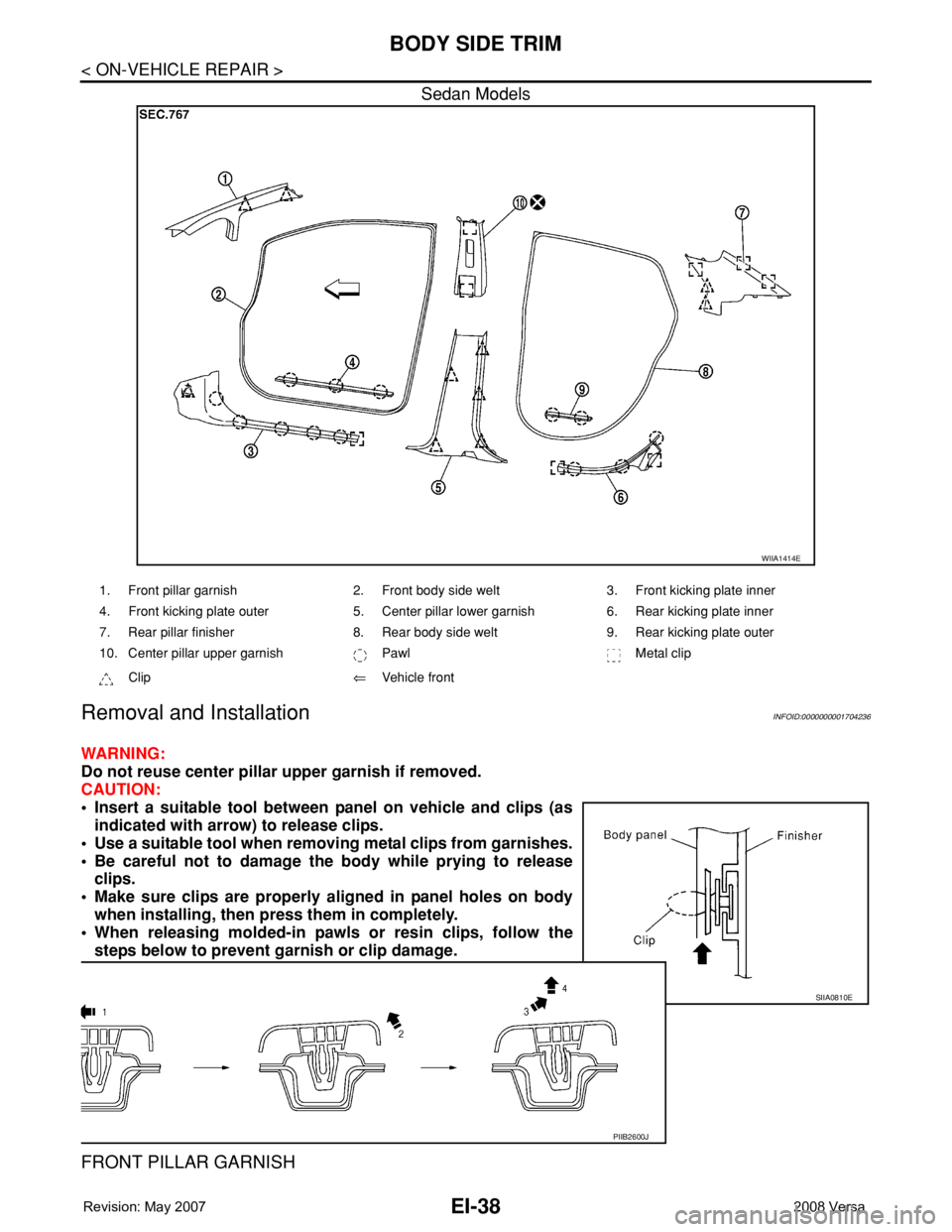
EI-38
< ON-VEHICLE REPAIR >
BODY SIDE TRIM
Sedan Models
Removal and InstallationINFOID:0000000001704236
WARNING:
Do not reuse center pillar upper garnish if removed.
CAUTION:
• Insert a suitable tool between panel on vehicle and clips (as
indicated with arrow) to release clips.
• Use a suitable tool when removing metal clips from garnishes.
• Be careful not to damage the body while prying to release
clips.
• Make sure clips are properly aligned in panel holes on body
when installing, then press them in completely.
• When releasing molded-in pawls or resin clips, follow the
steps below to prevent garnish or clip damage.
FRONT PILLAR GARNISH
WIIA1414E
1. Front pillar garnish 2. Front body side welt 3. Front kicking plate inner
4. Front kicking plate outer 5. Center pillar lower garnish 6. Rear kicking plate inner
7. Rear pillar finisher 8. Rear body side welt 9. Rear kicking plate outer
10. Center pillar upper garnish Pawl Metal clip
Clip⇐Vehicle front
SIIA0810E
PIIB2600J
Page 1662 of 2771
BODY SIDE TRIM
EI-39
< ON-VEHICLE REPAIR >
C
D
E
F
G
H
J
K
L
MA
B
EI
N
O
P Removal
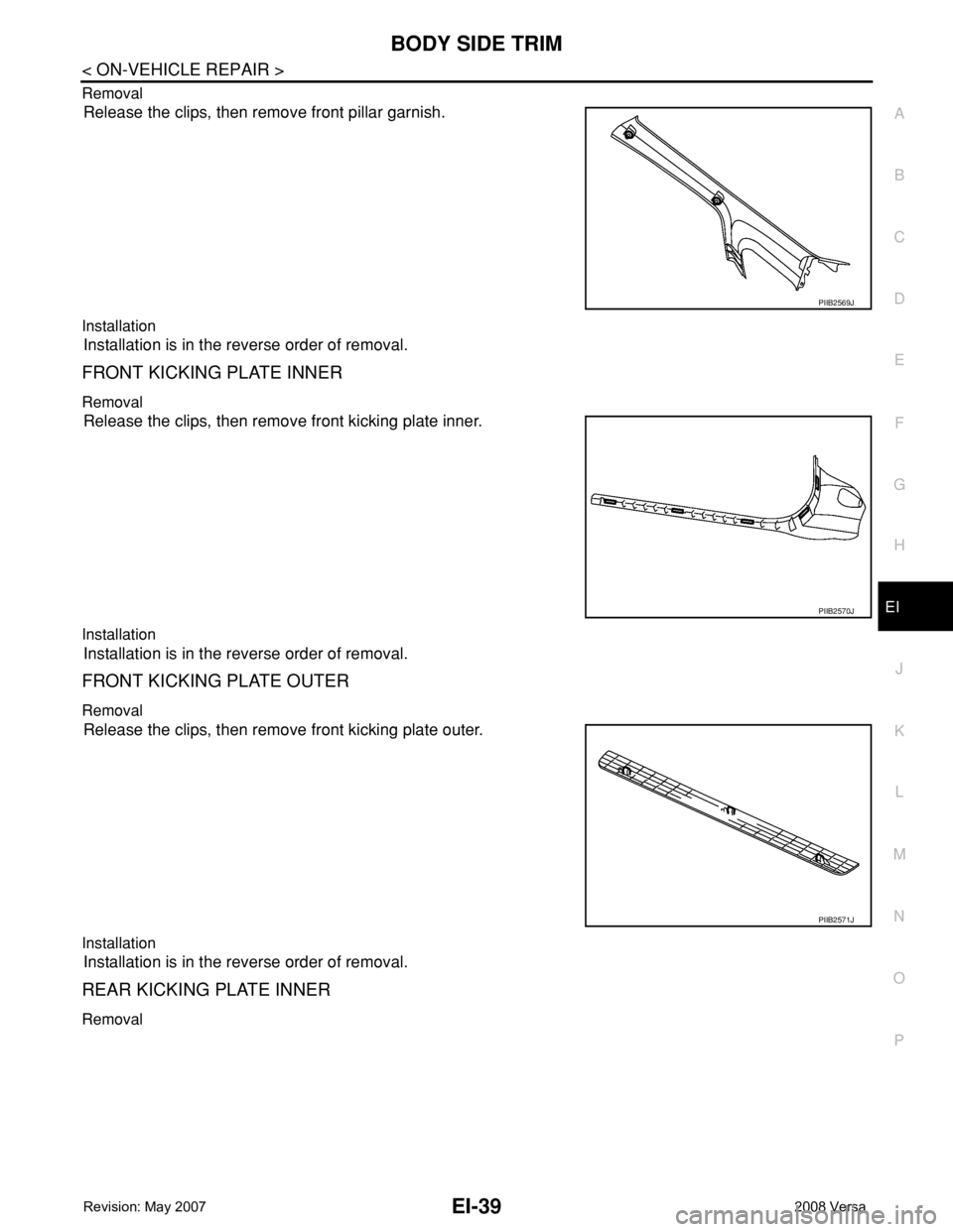
Release the clips, then remove front pillar garnish.
Installation
Installation is in the reverse order of removal.
FRONT KICKING PLATE INNER
Removal
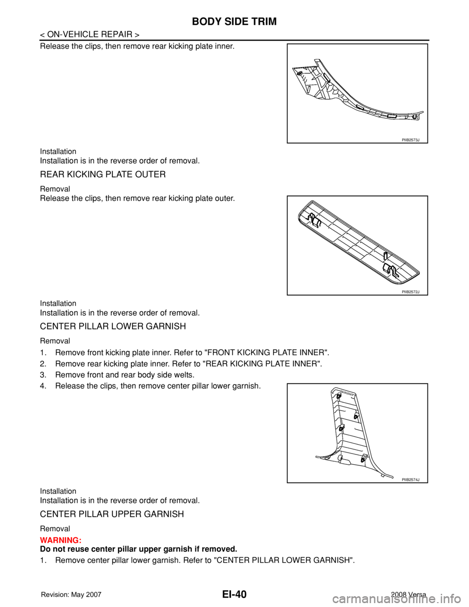
Release the clips, then remove front kicking plate inner.
Installation
Installation is in the reverse order of removal.
FRONT KICKING PLATE OUTER
Removal
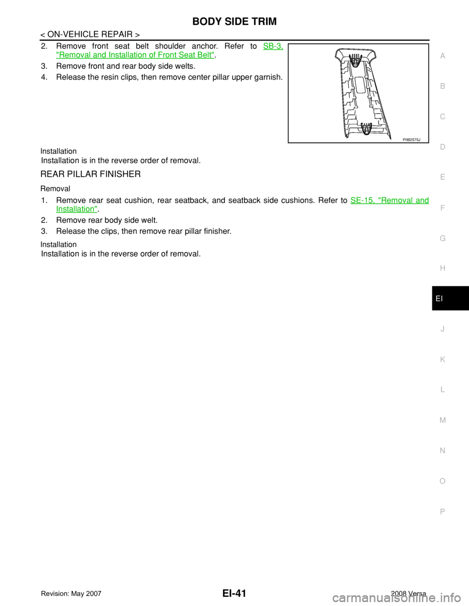
Release the clips, then remove front kicking plate outer.
Installation
Installation is in the reverse order of removal.
REAR KICKING PLATE INNER
Removal
PIIB2569J
PIIB2570J
PIIB2571J
Page 1663 of 2771
EI-40
< ON-VEHICLE REPAIR >
BODY SIDE TRIM
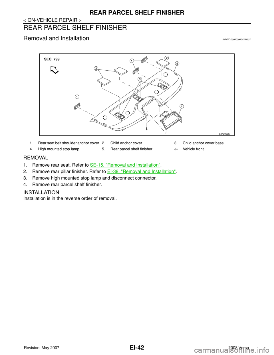
Release the clips, then remove rear kicking plate inner.
Installation
Installation is in the reverse order of removal.
REAR KICKING PLATE OUTER
Removal
Release the clips, then remove rear kicking plate outer.
Installation
Installation is in the reverse order of removal.
CENTER PILLAR LOWER GARNISH
Removal
1. Remove front kicking plate inner. Refer to "FRONT KICKING PLATE INNER".
2. Remove rear kicking plate inner. Refer to "REAR KICKING PLATE INNER".
3. Remove front and rear body side welts.
4. Release the clips, then remove center pillar lower garnish.
Installation
Installation is in the reverse order of removal.
CENTER PILLAR UPPER GARNISH
Removal
WARNING:
Do not reuse center pillar upper garnish if removed.
1. Remove center pillar lower garnish. Refer to "CENTER PILLAR LOWER GARNISH".
PIIB2573J
PIIB2572J
PIIB2574J
Page 1664 of 2771
BODY SIDE TRIM
EI-41
< ON-VEHICLE REPAIR >
C
D
E
F
G
H
J
K
L
MA
B
EI
N
O
P
2. Remove front seat belt shoulder anchor. Refer to SB-3,
"Removal and Installation of Front Seat Belt".
3. Remove front and rear body side welts.
4. Release the resin clips, then remove center pillar upper garnish.
Installation
Installation is in the reverse order of removal.
REAR PILLAR FINISHER
Removal
1. Remove rear seat cushion, rear seatback, and seatback side cushions. Refer to SE-15, "Removal and
Installation".
2. Remove rear body side welt.
3. Release the clips, then remove rear pillar finisher.
Installation
Installation is in the reverse order of removal.
PIIB2575J
Page 1665 of 2771
EI-42
< ON-VEHICLE REPAIR >
REAR PARCEL SHELF FINISHER
REAR PARCEL SHELF FINISHER
Removal and InstallationINFOID:0000000001704237
REMOVAL
1. Remove rear seat. Refer to SE-15, "Removal and Installation".
2. Remove rear pillar finisher. Refer to EI-38, "
Removal and Installation".
3. Remove high mounted stop lamp and disconnect connector.
4. Remove rear parcel shelf finisher.
INSTALLATION
Installation is in the reverse order of removal.
LIIA2923E
1. Rear seat belt shoulder anchor cover 2. Child anchor cover 3. Child anchor cover base
4. High mounted stop lamp 5. Rear parcel shelf finisher⇐Vehicle front
Page 1666 of 2771
FLOOR TRIM
EI-43
< ON-VEHICLE REPAIR >
C
D
E
F
G
H
J
K
L
MA
B
EI
N
O
P
FLOOR TRIM
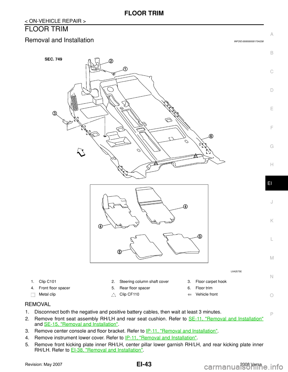
Removal and InstallationINFOID:0000000001704238
REMOVAL
1. Disconnect both the negative and positive battery cables, then wait at least 3 minutes.
2. Remove front seat assembly RH/LH and rear seat cushion. Refer to SE-11, "
Removal and Installation"
and SE-15, "Removal and Installation".
3. Remove center console and floor bracket. Refer to IP-11, "
Removal and Installation".
4. Remove instrument lower cover. Refer to IP-11, "
Removal and Installation".
5. Remove front kicking plate inner RH/LH, center pillar lower garnish RH/LH, and rear kicking plate inner
RH/LH. Refer to EI-38, "
Removal and Installation".
1. Clip C101 2. Steering column shaft cover 3. Floor carpet hook
4. Front floor spacer 5. Rear floor spacer 6. Floor trim
Metal clip Clip CF110⇐Vehicle front
LIIA2575E
Page 1667 of 2771
EI-44
< ON-VEHICLE REPAIR >
FLOOR TRIM
6. Disconnect floor harness connector.
7. Remove diagnosis sensor unit. Refer to SRS-44
.
8. Remove key interlock cable. Refer to AT-213
.
9. Remove floor carpet hook.
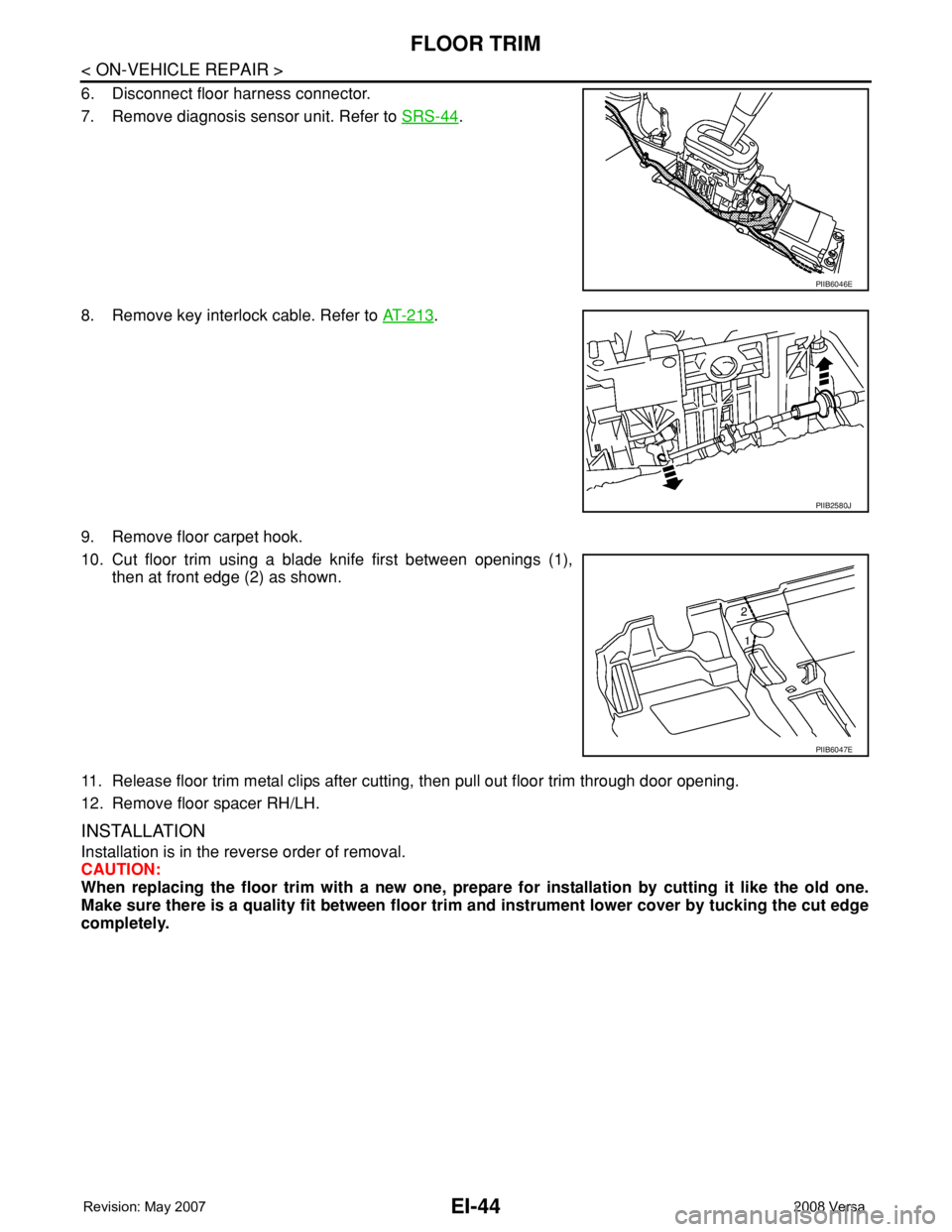
10. Cut floor trim using a blade knife first between openings (1),
then at front edge (2) as shown.
11. Release floor trim metal clips after cutting, then pull out floor trim through door opening.
12. Remove floor spacer RH/LH.
INSTALLATION
Installation is in the reverse order of removal.
CAUTION:
When replacing the floor trim with a new one, prepare for installation by cutting it like the old one.
Make sure there is a quality fit between floor trim and instrument lower cover by tucking the cut edge
completely.
PIIB6046E
PIIB2580J
PIIB6047E
Page 1668 of 2771
HEADLINING
EI-45
< ON-VEHICLE REPAIR >
C
D
E
F
G
H
J
K
L
MA
B
EI
N
O
P
HEADLINING
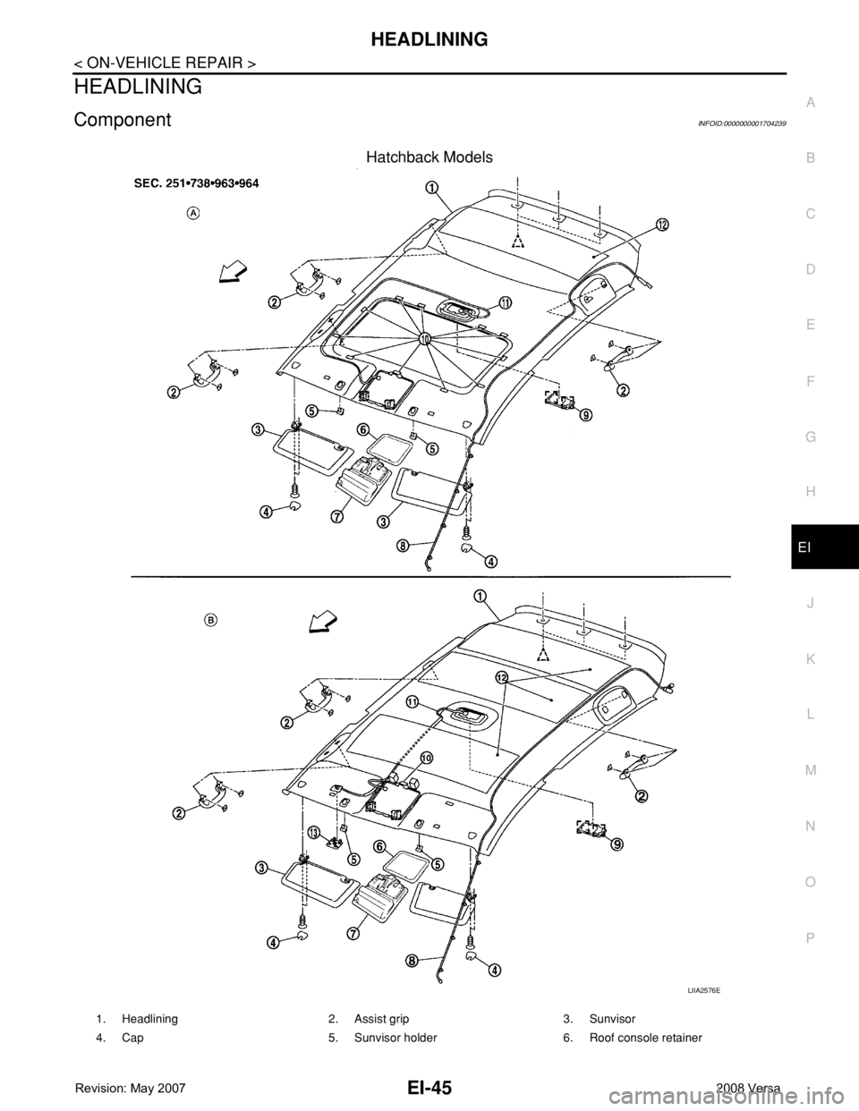
ComponentINFOID:0000000001704239
Hatchback Models
LIIA2576E
1. Headlining 2. Assist grip 3. Sunvisor
4. Cap 5. Sunvisor holder 6. Roof console retainer
Page 1669 of 2771
EI-46
< ON-VEHICLE REPAIR >
HEADLINING
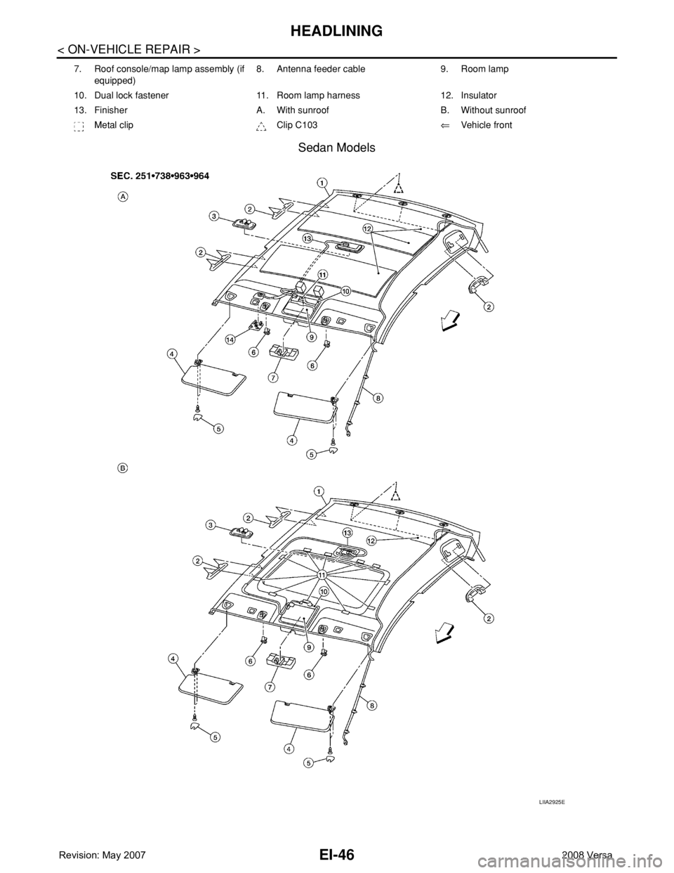
Sedan Models
7. Roof console/map lamp assembly (if
equipped)8. Antenna feeder cable 9. Room lamp
10. Dual lock fastener 11. Room lamp harness 12. Insulator
13. Finisher A. With sunroof B. Without sunroof
Metal clip Clip C103⇐Vehicle front
LIIA2925E
Page 1670 of 2771
HEADLINING
EI-47
< ON-VEHICLE REPAIR >
C
D
E
F
G
H
J
K
L
MA
B
EI
N
O
P
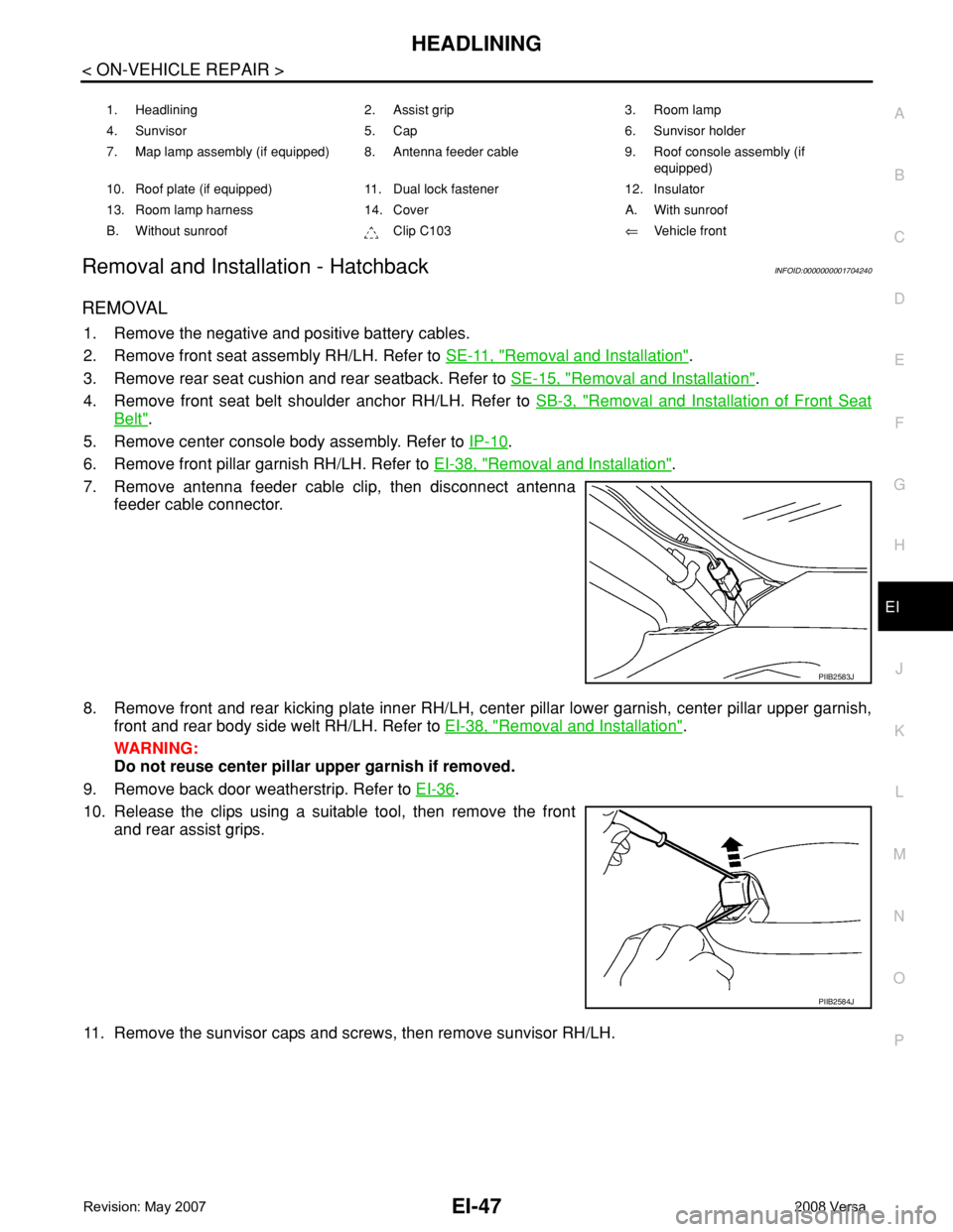
Removal and Installation - HatchbackINFOID:0000000001704240
REMOVAL
1. Remove the negative and positive battery cables.
2. Remove front seat assembly RH/LH. Refer to SE-11, "
Removal and Installation".
3. Remove rear seat cushion and rear seatback. Refer to SE-15, "
Removal and Installation".
4. Remove front seat belt shoulder anchor RH/LH. Refer to SB-3, "
Removal and Installation of Front Seat
Belt".
5. Remove center console body assembly. Refer to IP-10
.
6. Remove front pillar garnish RH/LH. Refer to EI-38, "
Removal and Installation".
7. Remove antenna feeder cable clip, then disconnect antenna
feeder cable connector.
8. Remove front and rear kicking plate inner RH/LH, center pillar lower garnish, center pillar upper garnish,
front and rear body side welt RH/LH. Refer to EI-38, "
Removal and Installation".
WARNING:
Do not reuse center pillar upper garnish if removed.
9. Remove back door weatherstrip. Refer to EI-36
.
10. Release the clips using a suitable tool, then remove the front
and rear assist grips.
11. Remove the sunvisor caps and screws, then remove sunvisor RH/LH.
1. Headlining 2. Assist grip 3. Room lamp
4. Sunvisor 5. Cap 6. Sunvisor holder
7. Map lamp assembly (if equipped) 8. Antenna feeder cable 9. Roof console assembly (if
equipped)
10. Roof plate (if equipped) 11. Dual lock fastener 12. Insulator
13. Room lamp harness 14. Cover A. With sunroof
B. Without sunroof Clip C103⇐Vehicle front
PIIB2583J
PIIB2584J
Trending: lan, airbag, maintenance, fuse, fuel tank removal, door switch, turn signal bulb

