NISSAN TIIDA 2008 Service Repair Manual
Manufacturer: NISSAN, Model Year: 2008, Model line: TIIDA, Model: NISSAN TIIDA 2008Pages: 2771, PDF Size: 60.61 MB
Page 1951 of 2771

GW-50
< SERVICE INFORMATION >
REAR WINDOW DEFOGGER
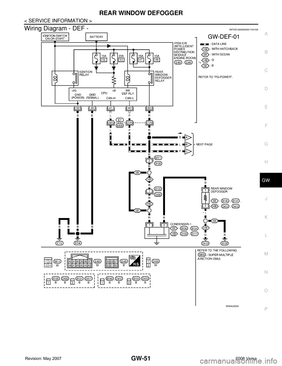
Power is supplied at all times
• through 15A fuses (No. 46 and 47, located in the IPDM E/R)
• to rear window defogger relay
• through 10A fuse [No. 5 (with heated mirrors), located in the fuse block (J/B)]
• to heated mirror relay terminal 3
• through 40A fusible link (letter g , located in the fuse and fusible link box)
• to BCM terminal 70.
With the ignition switch turned to ON or START position, power is supplied
• through ignition relay
• to rear window defogger relay (located in the IPDM E/R)
• through 10A fuse [No. 6, located in the fuse block (J/B)]
• to BCM terminal 38.
Ground is supplied
• to BCM terminal 67 and
• to front air control terminal 8
• through body grounds M57 and M61
• to IPDM E/R terminals 39 and 59
• through body grounds E15 and E24.
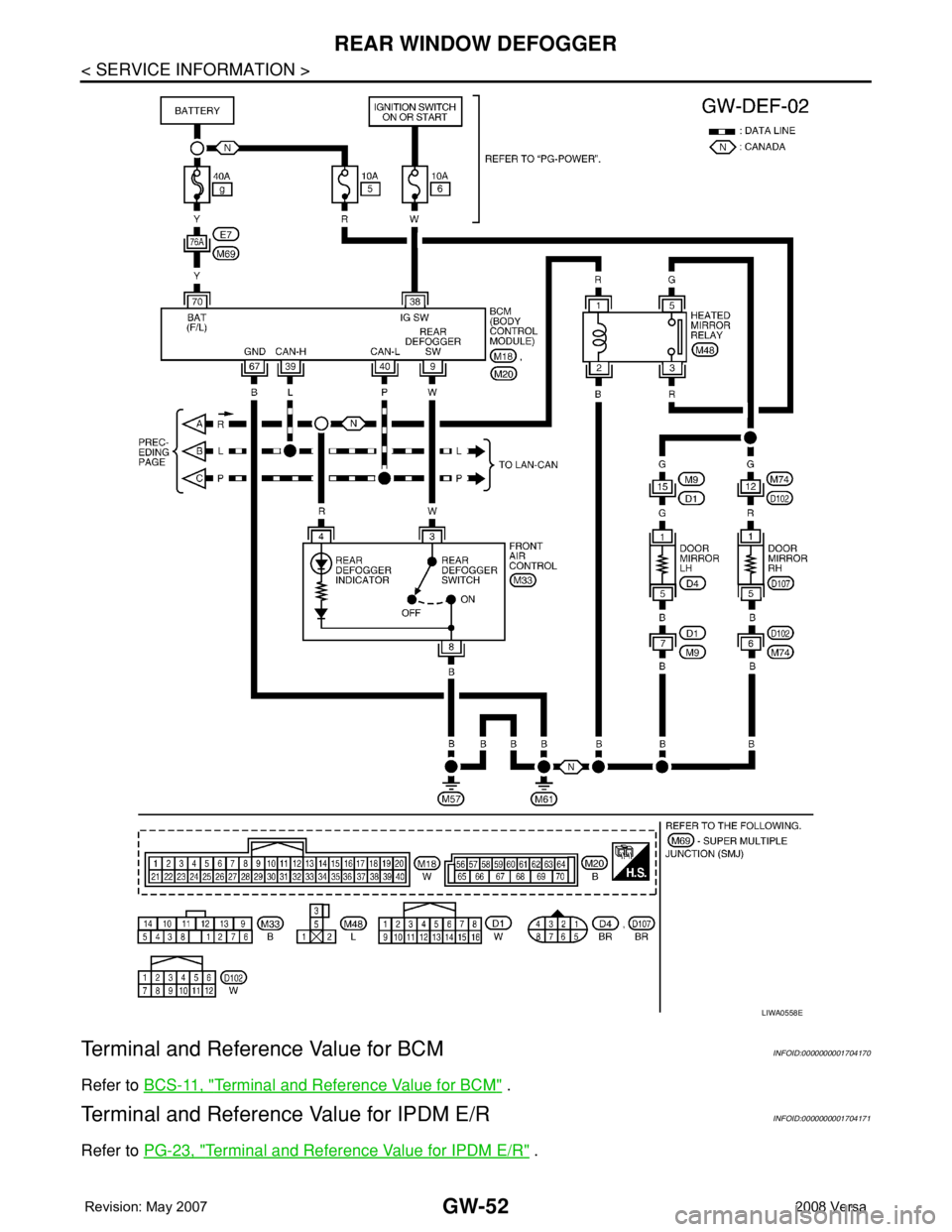
When front air control (rear window defogger switch) is turned to ON, ground is supplied
• to BCM terminal 9
• through front air control terminal 3
• through front air control terminal 8
• through body grounds M57 and M61.
Then rear window defogger switch is illuminated.
Then BCM recognizes that rear window defogger switch is turned to ON.
Then it sends rear window defogger switch signals to IPDM E/R via CAN communication (CAN-H, CAN-L).
When IPDM E/R receives rear window defogger switch signals, ground is supplied
• to rear window defogger relay (located in the IPDM E/R)
• through IPDM E/R terminals 39 and 59
• through body grounds E15 and E24
Then rear window defogger relay is energized.
With power and ground supplied, rear window defogger filaments heat and defog the rear window.
When rear window defogger relay is turned to ON (with heated mirrors), power is supplied
• through heated mirror relay terminal 5
• to door mirror (LH and RH) terminal 1.
Door mirror (LH and RH) is grounded through body grounds M57 and M61.
With power and ground supplied, rear window defogger filaments heat and defog the rear window and door
mirror filaments heat and defog the mirrors.
CAN Communication System DescriptionINFOID:0000000001704168
Refer to LAN-6, "System Description".
Page 1952 of 2771
REAR WINDOW DEFOGGER
GW-51
< SERVICE INFORMATION >
C
D
E
F
G
H
J
K
L
MA
B
GW
N
O
P
Wiring Diagram - DEF -INFOID:0000000001704169
WIWA2283E
Page 1953 of 2771
GW-52
< SERVICE INFORMATION >
REAR WINDOW DEFOGGER
Terminal and Reference Value for BCM
INFOID:0000000001704170
Refer to BCS-11, "Terminal and Reference Value for BCM" .
Terminal and Reference Value for IPDM E/RINFOID:0000000001704171
Refer to PG-23, "Terminal and Reference Value for IPDM E/R" .
LIWA0558E
Page 1954 of 2771
REAR WINDOW DEFOGGER
GW-53
< SERVICE INFORMATION >
C
D
E
F
G
H
J
K
L
MA
B
GW
N
O
P
Work FlowINFOID:0000000001704172
1. Check the symptom and customer's requests.
2. Understand the outline of system. Refer to GW-49, "
System Description" .
3. According to the trouble diagnosis chart, repair or replace the cause of the malfunction. Refer to GW-53,
"Trouble Diagnosis Symptom Chart" .
4. Does rear window defogger operate normally? YES: GO TO 5, NO: GO TO 3.
5. Inspection End.
CONSULT-III Function (BCM)INFOID:0000000001704173
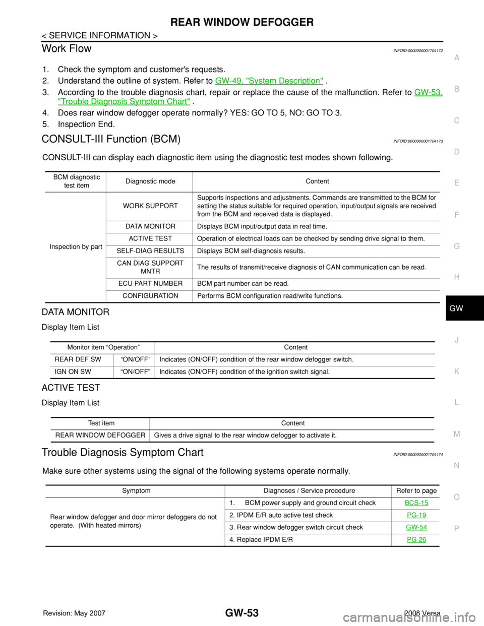
CONSULT-III can display each diagnostic item using the diagnostic test modes shown following.
DATA MONITOR
Display Item List
ACTIVE TEST
Display Item List
Trouble Diagnosis Symptom ChartINFOID:0000000001704174
Make sure other systems using the signal of the following systems operate normally.
BCM diagnostic
test itemDiagnostic mode Content
Inspection by partWORK SUPPORTSupports inspections and adjustments. Commands are transmitted to the BCM for
setting the status suitable for required operation, input/output signals are received
from the BCM and received data is displayed.
DATA MONITOR Displays BCM input/output data in real time.
ACTIVE TEST Operation of electrical loads can be checked by sending drive signal to them.
SELF-DIAG RESULTS Displays BCM self-diagnosis results.
CAN DIAG SUPPORT
MNTRThe results of transmit/receive diagnosis of CAN communication can be read.
ECU PART NUMBER BCM part number can be read.
CONFIGURATION Performs BCM configuration read/write functions.
Monitor item “Operation” Content
REAR DEF SW “ON/OFF” Indicates (ON/OFF) condition of the rear window defogger switch.
IGN ON SW “ON/OFF” Indicates (ON/OFF) condition of the ignition switch signal.
Test item Content
REAR WINDOW DEFOGGER Gives a drive signal to the rear window defogger to activate it.
Symptom Diagnoses / Service procedure Refer to page
Rear window defogger and door mirror defoggers do not
operate. (With heated mirrors)1. BCM power supply and ground circuit checkBCS-15
2. IPDM E/R auto active test checkPG-19
3. Rear window defogger switch circuit checkGW-54
4. Replace IPDM E/RPG-26
Page 1955 of 2771
GW-54
< SERVICE INFORMATION >
REAR WINDOW DEFOGGER
BCM Power Supply and Ground Circuit Inspection
INFOID:0000000001704175
Refer to BCS-15, "BCM Power Supply and Ground Circuit Inspection" .
Rear Window Defogger Switch Circuit InspectionINFOID:0000000001704176
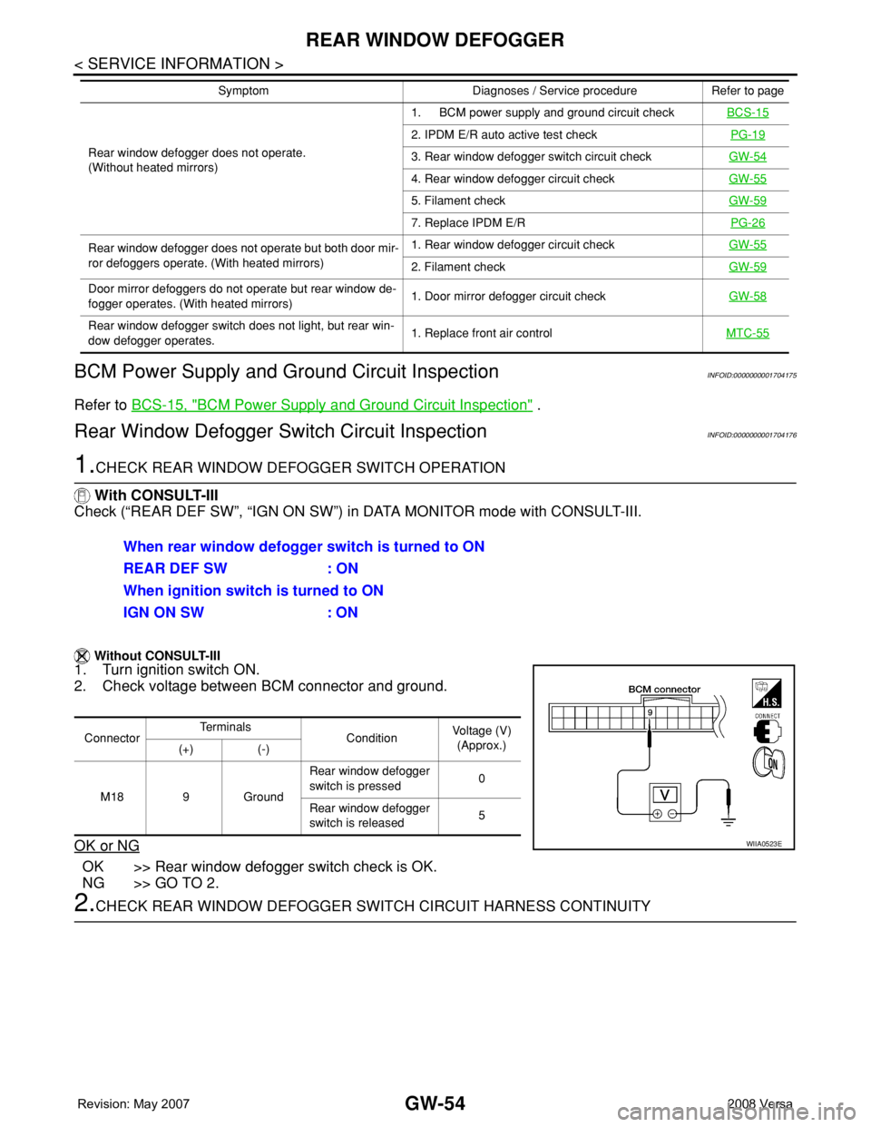
1.CHECK REAR WINDOW DEFOGGER SWITCH OPERATION
With CONSULT-III
Check (“REAR DEF SW”, “IGN ON SW”) in DATA MONITOR mode with CONSULT-III.
Without CONSULT-III
1. Turn ignition switch ON.
2. Check voltage between BCM connector and ground.
OK or NG
OK >> Rear window defogger switch check is OK.
NG >> GO TO 2.
2.CHECK REAR WINDOW DEFOGGER SWITCH CIRCUIT HARNESS CONTINUITY
Rear window defogger does not operate.
(Without heated mirrors)1. BCM power supply and ground circuit checkBCS-15
2. IPDM E/R auto active test checkPG-19
3. Rear window defogger switch circuit checkGW-54
4. Rear window defogger circuit checkGW-55
5. Filament checkGW-59
7. Replace IPDM E/RPG-26
Rear window defogger does not operate but both door mir-
ror defoggers operate. (With heated mirrors)1. Rear window defogger circuit checkGW-55
2. Filament checkGW-59
Door mirror defoggers do not operate but rear window de-
fogger operates. (With heated mirrors)1. Door mirror defogger circuit checkGW-58
Rear window defogger switch does not light, but rear win-
dow defogger operates.1. Replace front air controlMTC-55
Symptom Diagnoses / Service procedure Refer to page
When rear window defogger switch is turned to ON
REAR DEF SW : ON
When ignition switch is turned to ON
IGN ON SW : ON
ConnectorTe r m i n a l s
ConditionVoltage (V)
(Approx.)
(+) (-)
M18 9 GroundRear window defogger
switch is pressed0
Rear window defogger
switch is released5
WIIA0523E
Page 1956 of 2771
REAR WINDOW DEFOGGER
GW-55
< SERVICE INFORMATION >
C
D
E
F
G
H
J
K
L
MA
B
GW
N
O
P
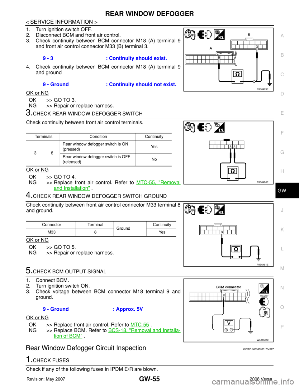
1. Turn ignition switch OFF.
2. Disconnect BCM and front air control.
3. Check continuity between BCM connector M18 (A) terminal 9
and front air control connector M33 (B) terminal 3.
4. Check continuity between BCM connector M18 (A) terminal 9
and ground
OK or NG
OK >> GO TO 3.
NG >> Repair or replace harness.
3.CHECK REAR WINDOW DEFOGGER SWITCH
Check continuity between front air control terminals.
OK or NG
OK >> GO TO 4.
NG >> Replace front air control. Refer to MTC-55, "
Removal
and Installation" .
4.CHECK REAR WINDOW DEFOGGER SWITCH GROUND
Check continuity between front air control connector M33 terminal 8
and ground.
OK or NG
OK >> GO TO 5.
NG >> Repair or replace harness.
5.CHECK BCM OUTPUT SIGNAL
1. Connect BCM.
2. Turn ignition switch ON.
3. Check voltage between BCM connector M18 terminal 9 and
ground.
OK or NG
OK >> Replace front air control. Refer to MTC-55 .
NG >> Replace BCM. Refer to BCS-18, "
Removal and Installa-
tion of BCM" .
Rear Window Defogger Circuit InspectionINFOID:0000000001704177
1.CHECK FUSES
Check if any of the following fuses in IPDM E/R are blown.9 - 3 : Continuity should exist.
9 - Ground : Continuity should not exist.
PIIB6479E
Terminals Condition Continuity
38Rear window defogger switch is ON
(pressed)Ye s
Rear window defogger switch is OFF
(released)No
PIIB6480E
Connector Terminal
GroundContinuity
8Yes M33
PIIB6481E
9 - Ground : Approx. 5V
WIIA0523E
Page 1957 of 2771
GW-56
< SERVICE INFORMATION >
REAR WINDOW DEFOGGER
OK or NG
OK >> GO TO 2.
NG >> If fuse is blown, be sure to eliminate cause of malfunction before installing new fuse.
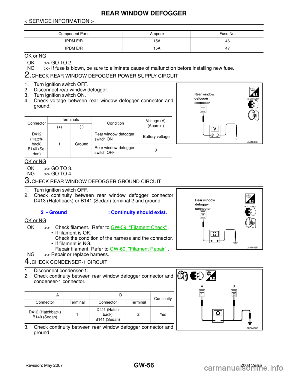
2.CHECK REAR WINDOW DEFOGGER POWER SUPPLY CIRCUIT
1. Turn ignition switch OFF.
2. Disconnect rear window defogger.
3. Turn ignition switch ON.
4. Check voltage between rear window defogger connector and
ground.
OK or NG
OK >> GO TO 3.
NG >> GO TO 4.
3.CHECK REAR WINDOW DEFOGGER GROUND CIRCUIT
1. Turn ignition switch OFF.
2. Check continuity between rear window defogger connector
D413 (Hatchback) or B141 (Sedan) terminal 2 and ground.
OK or NG
OK >> Check filament. Refer to GW-59, "Filament Check" .
• If filament is OK.
Check the condition of the harness and the connector.
• If filament is NG.
Repair filament. Refer to GW-60, "
Filament Repair" .
NG >> Repair or replace harness.
4.CHECK CONDENSER-1 CIRCUIT
1. Disconnect condenser-1.
2. Check continuity between rear window defogger connector and
condenser-1 connector.
3. Check continuity between rear window defogger connector and
ground.
Component Parts Ampere Fuse No.
IPDM E/R 15A 46
IPDM E/R 15A 47
ConnectorTe r m i n a l s
ConditionVoltage (V)
(Approx.)
(+) (-)
D412
(Hatch-
back)
B140 (Se-
dan)1GroundRear window defogger
switch ON Battery voltage
Rear window defogger
switch OFF0
LIIA1847E
2 - Ground : Continuity should exist.
LIIA1848E
AB
Continuity
Connector Terminal Connector Terminal
D412 (Hatchback)
B140 (Sedan)1 D411 (Hatch-
back)
B141 (Sedan)2Yes
PIIB6486E
Page 1958 of 2771
REAR WINDOW DEFOGGER
GW-57
< SERVICE INFORMATION >
C
D
E
F
G
H
J
K
L
MA
B
GW
N
O
P
OK or NG
OK >> GO TO 5.
NG >> Repair or replace harness.
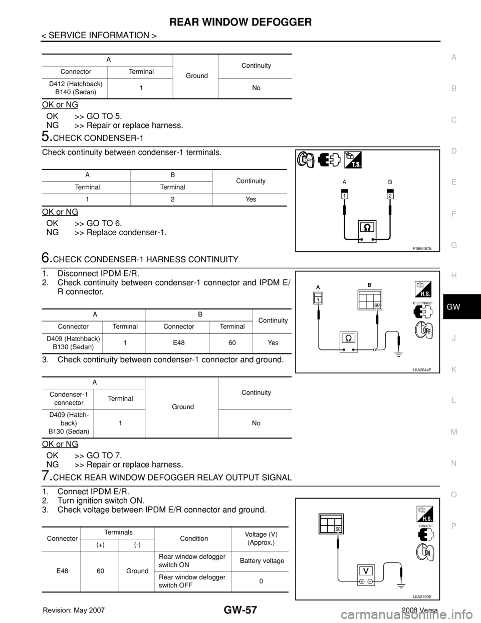
5.CHECK CONDENSER-1
Check continuity between condenser-1 terminals.
OK or NG
OK >> GO TO 6.
NG >> Replace condenser-1.
6.CHECK CONDENSER-1 HARNESS CONTINUITY
1. Disconnect IPDM E/R.
2. Check continuity between condenser-1 connector and IPDM E/
R connector.
3. Check continuity between condenser-1 connector and ground.
OK or NG
OK >> GO TO 7.
NG >> Repair or replace harness.
7.CHECK REAR WINDOW DEFOGGER RELAY OUTPUT SIGNAL
1. Connect IPDM E/R.
2. Turn ignition switch ON.
3. Check voltage between IPDM E/R connector and ground.
A
GroundContinuity
Connector Terminal
D412 (Hatchback)
B140 (Sedan)1No
AB
Continuity
Te r m i n a l Te r m i n a l
12Yes
PIIB6487E
AB
Continuity
Connector Terminal Connector Terminal
D409 (Hatchback)
B130 (Sedan)1 E48 60 Yes
A
GroundContinuity
Condenser-1
connectorTe r m i n a l
D409 (Hatch-
back)
B130 (Sedan)1No
LIIA2644E
ConnectorTe r m i n a l s
ConditionVoltage (V)
(Approx.)
(+) (-)
E48 60 GroundRear window defogger
switch ON Battery voltage
Rear window defogger
switch OFF0
LIIA2190E
Page 1959 of 2771
GW-58
< SERVICE INFORMATION >
REAR WINDOW DEFOGGER
OK or NG
OK >> Check condition of harness and connector.
NG >> Replace IPDM E/R. Refer to PG-26, "
Removal and Installation of IPDM E/R" .
Door Mirror Defogger Circuit InspectionINFOID:0000000001704178
1.CHECK FUSE
Check if the following fuse in the fuse block (J/B) is blown.
OK or NG
OK >> GO TO 2.
NG >> If fuse is blown, be sure to eliminate cause of malfunction before installing new fuse.
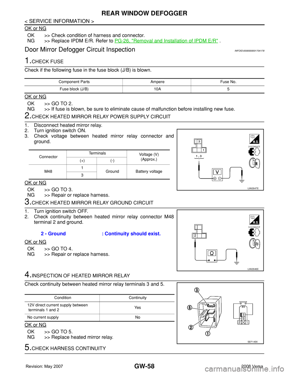
2.CHECK HEATED MIRROR RELAY POWER SUPPLY CIRCUIT
1. Disconnect heated mirror relay.
2. Turn ignition switch ON.
3. Check voltage between heated mirror relay connector and
ground.
OK or NG
OK >> GO TO 3.
NG >> Repair or replace harness.
3.CHECK HEATED MIRROR RELAY GROUND CIRCUIT
1. Turn ignition switch OFF.
2. Check continuity between heated mirror relay connector M48
terminal 2 and ground.
OK or NG
OK >> GO TO 4.
NG >> Repair or replace harness.
4.INSPECTION OF HEATED MIRROR RELAY
Check continuity between heated mirror relay terminals 3 and 5.
OK or NG
OK >> GO TO 5.
NG >> Replace heated mirror relay.
5.CHECK HARNESS CONTINUITY
Component Parts Ampere Fuse No.
Fuse block (J/B) 10A 5
ConnectorTe r m i n a l s
Voltage (V)
(Approx.)
(+) (-)
M481
Ground Battery voltage
3
LIIA2647E
2 - Ground : Continuity should exist.
LIIA2646E
Condition Continuity
12V direct current supply between
terminals 1 and 2Ye s
No current supply No
SEF145X
Page 1960 of 2771
REAR WINDOW DEFOGGER
GW-59
< SERVICE INFORMATION >
C
D
E
F
G
H
J
K
L
MA
B
GW
N
O
P
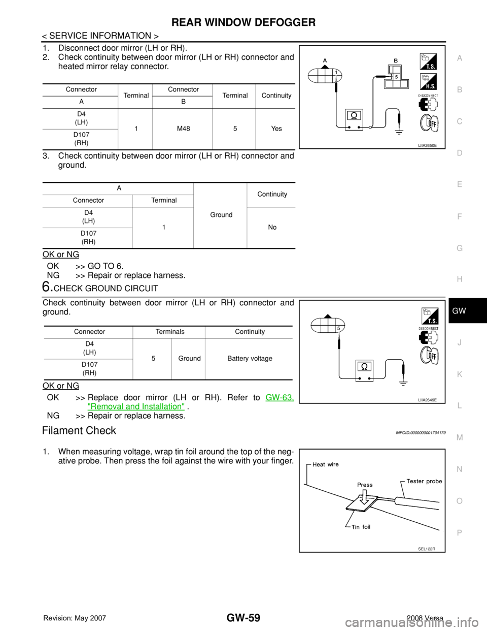
1. Disconnect door mirror (LH or RH).
2. Check continuity between door mirror (LH or RH) connector and
heated mirror relay connector.
3. Check continuity between door mirror (LH or RH) connector and
ground.
OK or NG
OK >> GO TO 6.
NG >> Repair or replace harness.
6.CHECK GROUND CIRCUIT
Check continuity between door mirror (LH or RH) connector and
ground.
OK or NG
OK >> Replace door mirror (LH or RH). Refer to GW-63,
"Removal and Installation" .
NG >> Repair or replace harness.
Filament CheckINFOID:0000000001704179
1. When measuring voltage, wrap tin foil around the top of the neg-
ative probe. Then press the foil against the wire with your finger.
Connector
Te r m i n a lConnector
Terminal Continuity
AB
D4
(LH)
1 M48 5 Yes
D107
(RH)
A
GroundContinuity
Connector Terminal
D4
(LH)
1No
D107
(RH)
LIIA2650E
Connector Terminals Continuity
D4
(LH)
5 Ground Battery voltage
D107
(RH)
LIIA2649E
SEL122R