Heater NISSAN TIIDA 2008 Service User Guide
[x] Cancel search | Manufacturer: NISSAN, Model Year: 2008, Model line: TIIDA, Model: NISSAN TIIDA 2008Pages: 2771, PDF Size: 60.61 MB
Page 1188 of 2771
![NISSAN TIIDA 2008 Service User Guide EC-114
< SERVICE INFORMATION >
TROUBLE DIAGNOSIS
FUEL T/TMP SE [°C]
or [°F]ו The fuel temperature (determined by the signal
voltage of the fuel tank temperature sensor) is
displayed.
INT/A TE](/img/5/57399/w960_57399-1187.png "NISSAN TIIDA 2008 Service User Guide EC-114
< SERVICE INFORMATION >
TROUBLE DIAGNOSIS
FUEL T/TMP SE [°C]
or [°F]ו The fuel temperature (determined by the signal
voltage of the fuel tank temperature sensor) is
displayed.
INT/A TE")
EC-114
< SERVICE INFORMATION >
TROUBLE DIAGNOSIS
FUEL T/TMP SE [°C]
or [°F]ו The fuel temperature (determined by the signal
voltage of the fuel tank temperature sensor) is
displayed.
INT/A TEMP SE
[°C] or [°F]×ו The intake air temperature (determined by the
signal voltage of the intake air temperature
sensor) is indicated.
EVAP SYS PRES [V]ו The signal voltage of EVAP control system
pressure sensor is displayed.
FUEL LEVEL SE [V]ו The signal voltage of the fuel level sensor is
displayed.
START SIGNAL
[ON/OFF]×ו Indicates start signal status [ON/OFF] comput-
ed by the ECM according to the signals of en-
gine speed and battery voltage.• After starting the engine, [OFF] is
displayed regardless of the starter
signal.
CLSD THL POS
[ON/OFF]×ו Indicates idle position [ON/OFF] computed by
the ECM according to the accelerator pedal po-
sition sensor signal.
AIR COND SIG
[ON/OFF]×ו Indicates [ON/OFF] condition of the air condi-
tioner switch as determined by the air condi-
tioner signal.
P/N POSI SW
[ON/OFF]×ו Indicates [ON/OFF] condition from the park/
neutral position (PNP) switch signal.
PW/ST SIGNAL [ON/
OFF]×ו [ON/OFF] condition of the power steering sys-
tem (determined by the signal sent from EPS
control unit) is indicated.
LOAD SIGNAL
[ON/OFF]×ו Indicates [ON/OFF] condition from the electri-
cal load signal.
ON: Rear window defogger switch is ON and/
or lighting switch is in 2nd position.
OFF: Both rear window defogger switch and
lighting switch are OFF.
IGNITION SW
[ON/OFF]ו Indicates [ON/OFF] condition from ignition
switch.
HEATER FAN SW
[ON/OFF]ו Indicates [ON/OFF] condition from the heater
fan switch signal.
BRAKE SW
[ON/OFF]ו Indicates [ON/OFF] condition from the stop
lamp switch signal.
INJ PULSE-B1
[msec]ו Indicates the actual fuel injection pulse width
compensated by ECM according to the input
signals.• When the engine is stopped, a
certain computed value is indicat-
ed.
IGN TIMING [BTDC]• Indicates the ignition timing computed by ECM
according to the input signals.• When the engine is stopped, a
certain value is indicated.
CAL/LD VALUE [%]• “Calculated load value” indicates the value of
the current airflow divided by peak airflow.
MASS AIRFLOW
[g·m/s]• Indicates the mass airflow computed by ECM
according to the signal voltage of the mass air
flow sensor.
PURG VOL C/V [%]• Indicates the EVAP canister purge volume con-
trol solenoid valve control value computed by
the ECM according to the input signals.
• The opening becomes larger as the value in-
creases.
INT/V TIM (B1) [°CA]• Indicates [°CA] of intake camshaft advanced
angle. Monitored item [Unit]ECM IN-
PUT SIG-
NALSMAIN
SIG-
NALSDescription Remarks
Page 1189 of 2771
![NISSAN TIIDA 2008 Service User Guide TROUBLE DIAGNOSIS
EC-115
< SERVICE INFORMATION >
C
D
E
F
G
H
I
J
K
L
MA
EC
N
P OINT/V SOL (B1) [%]• The control value of the intake valve timing
control solenoid valve (determined by ECM ac-
cordin](/img/5/57399/w960_57399-1188.png "NISSAN TIIDA 2008 Service User Guide TROUBLE DIAGNOSIS
EC-115
< SERVICE INFORMATION >
C
D
E
F
G
H
I
J
K
L
MA
EC
N
P OINT/V SOL (B1) [%]• The control value of the intake valve timing
control solenoid valve (determined by ECM ac-
cordin")
TROUBLE DIAGNOSIS
EC-115
< SERVICE INFORMATION >
C
D
E
F
G
H
I
J
K
L
MA
EC
N
P OINT/V SOL (B1) [%]• The control value of the intake valve timing
control solenoid valve (determined by ECM ac-
cording to the input signal) is indicated.
• The advance angle becomes larger as the val-
ue increases
AIR COND RLY
[ON/OFF]ו The air conditioner relay control condition (de-
termined by ECM according to the input sig-
nals) is indicated.
FUEL PUMP RLY
[ON/OFF]ו Indicates the fuel pump relay control condition
determined by ECM according to the input sig-
nals.
VENT CONT/V [ON/
OFF]• The control condition of the EVAP canister vent
control valve (determined by ECM according to
the input signals) is indicated.
ON: Closed
OFF: Open
THRTL RELAY
[ON/OFF]ו Indicates the throttle control motor relay control
condition determined by the ECM according to
the input signals.
COOLING FAN
[HI/LOW/OFF]ו Indicates the condition of the cooling fan (de-
termined by ECM according to the input sig-
nals).
HI: High speed operation
LOW: Low speed operation
OFF: Stop
HO2S2 HTR (B1)
[ON/OFF]• Indicates [ON/OFF] condition of heated oxygen
sensor 2 heater determined by ECM according
to the input signals.
I/P PULLY SPD
[rpm]• Indicates the engine speed computed from the
turbine revolution sensor signal.
VEHICLE SPEED
[km/h] or [MPH]ו The vehicle speed computed from the vehicle
speed signal sent from TCM is displayed.
IDL A/V LEARN
[YET/CMPLT]• Display the condition of idle air volume learning
YET: Idle Air Volume Learning has not been
performed yet.
CMPLT: Idle Air Volume Learning has already
been performed successfully.
TRVL AFTER MIL
[km] or [mile]• Distance traveled while MIL is activated.
A/F S1 HTR (B1) [%]• Indicates A/F sensor 1 heater control value
computed by ECM according to the input sig-
nals.
• The current flow to the heater becomes larger
as the value increases.
AC PRESS SEN [V]ו The signal voltage from the refrigerant pres-
sure sensor is displayed.
VHCL SPEED SE
[km/h] or [MPH]• The vehicle speed computed from the vehicle
speed signal sent from TCM is displayed.
SET VHCL SPD
[km/h] or [MPH]• The preset vehicle speed is displayed.
MAIN SW
[ON/OFF]• Indicates [ON/OFF] condition from MAIN
switch signal.
CANCEL SW
[ON/OFF]• Indicates [ON/OFF] condition from CANCEL
switch signal. Monitored item [Unit]ECM IN-
PUT SIG-
NALSMAIN
SIG-
NALSDescription Remarks
Page 1196 of 2771

EC-122
< SERVICE INFORMATION >
TROUBLE DIAGNOSIS
THRTL SEN 1
THRTL SEN 2*• Ignition switch: ON
(Engine stopped)Accelerator pedal: Fully released More than 0.36V
• Shift lever: D (A/T, CVT),
1st (M/T)Accelerator pedal: Fully depressed Less than 4.75V
START SIGNAL • Ignition switch: ON → START → ON OFF → ON → OFF
CLSD THL POS • Ignition switch: ONAccelerator pedal: Fully released ON
Accelerator pedal: Slightly depressed OFF
AIR COND SIG• Engine: After warming up, idle the
engineAir conditioner switch: OFF OFF
Air conditioner switch: ON
(Compressor operates.)ON
P/N POSI SW • Ignition switch: ONShift lever: P or N (A/T, CVT),
Neutral (M/T)ON
Shift lever: Except above OFF
PW/ST SIGNAL• Engine: After warming up, idle the
engineSteering wheel: Not being turned OFF
Steering wheel: Being turned ON
LOAD SIGNAL • Ignition switch: ONRear window defogger switch: ON
and/or Lighting switch: 2ndON
Rear window defogger switch and light-
ing switch: OFFOFF
IGNITION SW • Ignition switch: ON → OFF → ON ON → OFF → ON
HEATER FAN SW • Ignition switch: ONHeater fan: Operating ON
Heater fan: Not operating OFF
BRAKE SW • Ignition switch: ONBrake pedal: Fully released OFF
Brake pedal: Slightly depressed ON
INJ PULSE-B1• Engine: After warming up
• Air conditioner switch: OFF
• Shift lever: P or N (A/T, CVT),
Neutral (M/T)
•No loadIdle 2.0 - 3.0 msec
2,000 rpm 1.9 - 2.9 msec
IGN TIMING• Engine: After warming up
• Air conditioner switch: OFF
• Shift lever: P or N (A/T, CVT),
Neutral (M/T)
•No loadIdle 8° - 18° BTDC
2,000 rpm 25° - 45° BTDC
CAL/LD VALUE• Engine: After warming up
• Air conditioner switch: OFF
• Shift lever: P or N (A/T, CVT),
Neutral (M/T)
•No loadIdle 10% - 35%
2,500 rpm 10% - 35%
MASS AIRFLOW• Engine: After warming up
• Air conditioner switch: OFF
• Shift lever: P or N (A/T, CVT),
Neutral (M/T)
•No loadIdle 1.0 - 4.0 g·m/s
2,500 rpm 2.0 - 10.0 g·m/s
PURG VOL C/V• Engine: After warming up
• Air conditioner switch: OFF
• Shift lever: P or N (A/T, CVT),
Neutral (M/T)
•No loadIdle
(Accelerator pedal is not depressed
even slightly, after engine starting)0%
2,000 rpm 0 - 50%
INT/V TIM (B1)• Engine: After warming up
• Air conditioner switch: OFF
• Shift lever: P or N (A/T, CVT),
Neutral (M/T)
•No loadIdle−5° - 5°CA
When revving engine up to 2,000 rpm
quicklyApprox. 0° - 40°CA MONITOR ITEM CONDITION SPECIFICATION
Page 1225 of 2771

DTC P0031, P0032 A/F SENSOR 1 HEATER
EC-151
< SERVICE INFORMATION >
C
D
E
F
G
H
I
J
K
L
MA
EC
N
P O
DTC P0031, P0032 A/F SENSOR 1 HEATER
DescriptionINFOID:0000000001702624
SYSTEM DESCRIPTION
The ECM performs ON/OFF duty control of the A/F sensor 1 heater corresponding to the engine operating
condition to keep the temperature of A/F sensor 1 element at the specified range.
CONSULT-II Reference Value in Data Monitor ModeINFOID:0000000001702625
Specification data are reference values.
On Board Diagnosis LogicINFOID:0000000001702626
DTC Confirmation ProcedureINFOID:0000000001702627
NOTE:
If DTC Confirmation Procedure has been previously conducted, always turn ignition switch OFF and wait at
least 10 seconds before conducting the next test.
TESTING CONDITION:
Before performing the following procedure, confirm that battery voltage is between 10.5V and 16V at
idle.
With CONSULT-II
WITH CONSULT-II
1. Turn ignition switch ON and select “DATA MONITOR” mode with
CONSULT-II.
2. Start engine and run it for at least 10 seconds at idle speed.
3. If 1st trip DTC is detected, go to EC-153, "
Diagnosis Procedure".
Sensor Input Signal to ECMECM
functionActuator
Camshaft position sensor (PHASE)
Crankshaft position sensor (POS)Engine speed
Air fuel ratio (A/F) sensor 1
heater controlAir fuel ratio (A/F) sensor 1 heat-
er
Mass air flow sensor Amount of intake air
MONITOR ITEM CONDITION SPECIFICATION
A/F S1 HTR (B1)• Engine: After warming up, idle the engine
(More than 140 seconds after starting engine.)4 - 100%
DTC No.Trouble diagnosis
nameDTC detecting condition Possible cause
P0031
0031Air fuel ratio (A/F)
sensor 1 heater
control circuit lowThe current amperage in the air fuel ratio (A/F)
sensor 1 heater circuit is out of the normal range.
[An excessively low voltage signal is sent to ECM
through the air fuel ratio (A/F) sensor 1 heater.]• Harness or connectors
[Air fuel ratio (A/F) sensor 1 heater circuit is
open or shorted.]
• Air fuel ratio (A/F) sensor 1 heater
P0032
0032Air fuel ratio (A/F)
sensor 1 heater
control circuit highThe current amperage in the air fuel ratio (A/F)
sensor 1 heater circuit is out of the normal range.
[An excessively high voltage signal is sent to ECM
through the air fuel ratio (A/F) sensor 1 heater.]• Harness or connectors
[Air fuel ratio (A/F) sensor 1 heater circuit is
shorted.]
• Air fuel ratio (A/F) sensor 1 heater
SEF058Y
Page 1226 of 2771
EC-152
< SERVICE INFORMATION >
DTC P0031, P0032 A/F SENSOR 1 HEATER
WITH GST
Follow the procedure “WITH CONSULT-II” above.
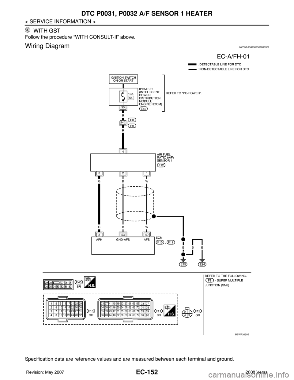
Wiring DiagramINFOID:0000000001702628
Specification data are reference values and are measured between each terminal and ground.
BBWA2630E
Page 1227 of 2771
DTC P0031, P0032 A/F SENSOR 1 HEATER
EC-153
< SERVICE INFORMATION >
C
D
E
F
G
H
I
J
K
L
MA
EC
N
P O
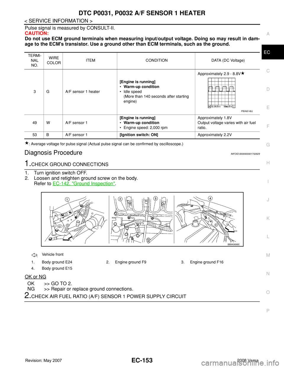
Pulse signal is measured by CONSULT-II.
CAUTION:
Do not use ECM ground terminals when measuring input/output voltage. Doing so may result in dam-
age to the ECM's transistor. Use a ground other than ECM terminals, such as the ground.
: Average voltage for pulse signal (Actual pulse signal can be confirmed by oscilloscope.)
Diagnosis ProcedureINFOID:0000000001702629
1.CHECK GROUND CONNECTIONS
1. Turn ignition switch OFF.
2. Loosen and retighten ground screw on the body.
Refer to EC-142, "
Ground Inspection".
OK or NG
OK >> GO TO 2.
NG >> Repair or replace ground connections.
2.CHECK AIR FUEL RATIO (A/F) SENSOR 1 POWER SUPPLY CIRCUIT
TERMI-
NAL
NO.WIRE
COLORITEM CONDITION DATA (DC Voltage)
3 G A/F sensor 1 heater[Engine is running]
•Warm-up condition
• Idle speed
(More than 140 seconds after starting
engine)Approximately 2.9 - 8.8V
49 W A/F sensor 1[Engine is running]
•Warm-up condition
• Engine speed: 2,000 rpmApproximately 1.8V
Output voltage varies with air fuel
ratio.
53 B A/F sensor 1[Ignition switch: ON]Approximately 2.2V
PBIA8148J
:Vehicle front
1. Body ground E24 2. Engine ground F9 3. Engine ground F16
4. Body ground E15
BBIA0698E
Page 1228 of 2771
EC-154
< SERVICE INFORMATION >
DTC P0031, P0032 A/F SENSOR 1 HEATER
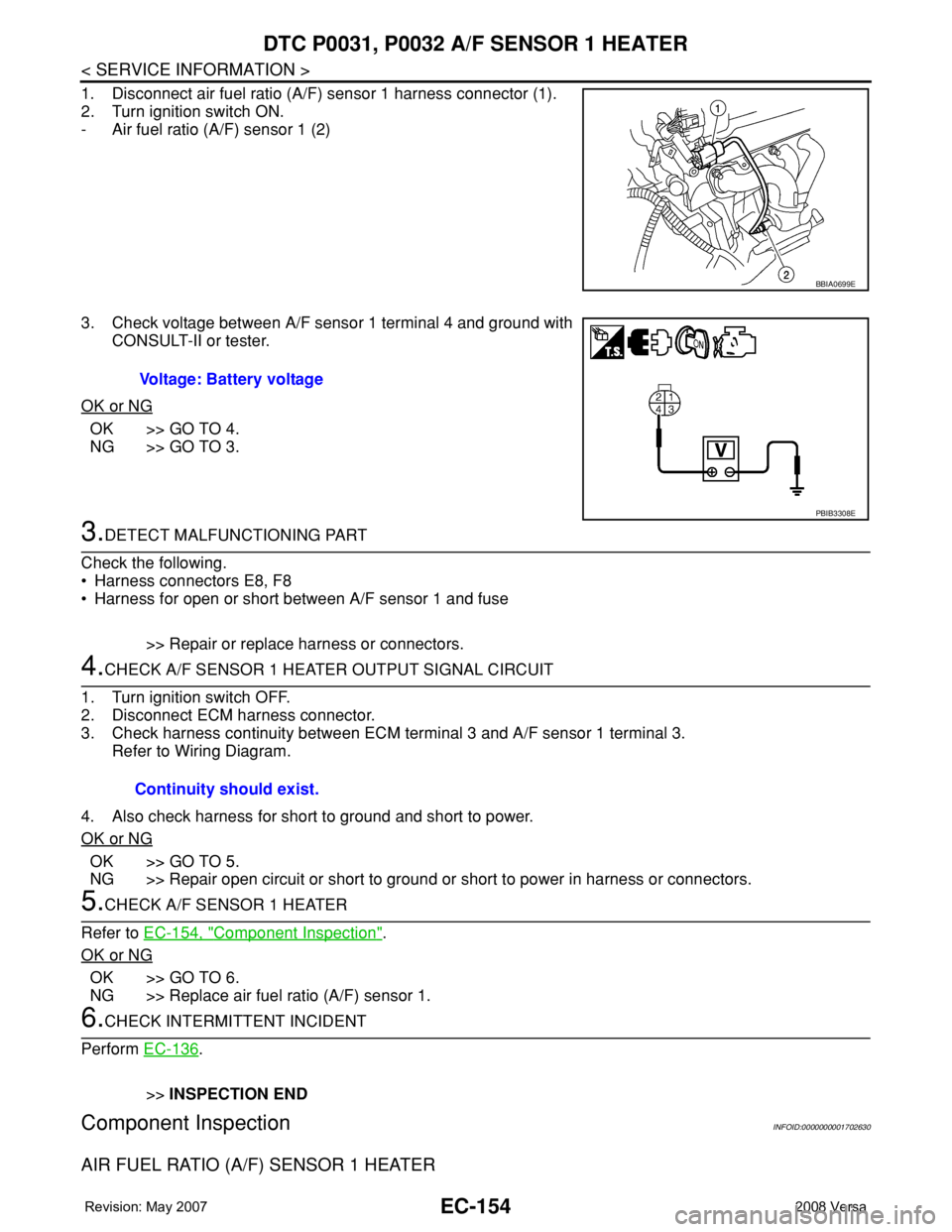
1. Disconnect air fuel ratio (A/F) sensor 1 harness connector (1).
2. Turn ignition switch ON.
- Air fuel ratio (A/F) sensor 1 (2)
3. Check voltage between A/F sensor 1 terminal 4 and ground with
CONSULT-II or tester.
OK or NG
OK >> GO TO 4.
NG >> GO TO 3.
3.DETECT MALFUNCTIONING PART
Check the following.
• Harness connectors E8, F8
• Harness for open or short between A/F sensor 1 and fuse
>> Repair or replace harness or connectors.
4.CHECK A/F SENSOR 1 HEATER OUTPUT SIGNAL CIRCUIT
1. Turn ignition switch OFF.
2. Disconnect ECM harness connector.
3. Check harness continuity between ECM terminal 3 and A/F sensor 1 terminal 3.
Refer to Wiring Diagram.
4. Also check harness for short to ground and short to power.
OK or NG
OK >> GO TO 5.
NG >> Repair open circuit or short to ground or short to power in harness or connectors.
5.CHECK A/F SENSOR 1 HEATER
Refer to EC-154, "
Component Inspection".
OK or NG
OK >> GO TO 6.
NG >> Replace air fuel ratio (A/F) sensor 1.
6.CHECK INTERMITTENT INCIDENT
Perform EC-136
.
>>INSPECTION END
Component InspectionINFOID:0000000001702630
AIR FUEL RATIO (A/F) SENSOR 1 HEATER
BBIA0699E
Voltage: Battery voltage
PBIB3308E
Continuity should exist.
Page 1229 of 2771
DTC P0031, P0032 A/F SENSOR 1 HEATER
EC-155
< SERVICE INFORMATION >
C
D
E
F
G
H
I
J
K
L
MA
EC
N
P O
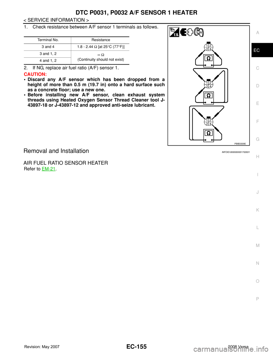
1. Check resistance between A/F sensor 1 terminals as follows.
2. If NG, replace air fuel ratio (A/F) sensor 1.
CAUTION:
• Discard any A/F sensor which has been dropped from a
height of more than 0.5 m (19.7 in) onto a hard surface such
as a concrete floor; use a new one.
• Before installing new A/F sensor, clean exhaust system
threads using Heated Oxygen Sensor Thread Cleaner tool J-
43897-18 or J-43897-12 and approved anti-seize lubricant.
Removal and InstallationINFOID:0000000001702631
AIR FUEL RATIO SENSOR HEATER
Refer to EM-21.
Terminal No. Resistance
3 and 4 1.8 - 2.44 Ω [at 25°C (77°F)]
3 and 1, 2
∞ Ω
(Continuity should not exist)
4 and 1, 2
PBIB3309E
Page 1230 of 2771

EC-156
< SERVICE INFORMATION >
DTC P0037, P0038 HO2S2 HEATER
DTC P0037, P0038 HO2S2 HEATER
DescriptionINFOID:0000000001702632
SYSTEM DESCRIPTION
The ECM performs ON/OFF control of the heated oxygen sensor 2 heater corresponding to the engine speed,
amount of intake air and engine coolant temperature.
OPERATION
CONSULT-II Reference Value in Data Monitor ModeINFOID:0000000001702633
Specification data are reference values.
On Board Diagnosis LogicINFOID:0000000001702634
DTC Confirmation ProcedureINFOID:0000000001702635
NOTE:
If DTC Confirmation Procedure has been previously conducted, always turn ignition switch OFF and wait at
least 10 seconds before conducting the next test.
TESTING CONDITION:
Before performing the following procedure, confirm that battery voltage is between 10.5V and 16V at
idle.
WITH CONSULT-II
Sensor Input Signal to ECM ECM Function Actuator
Camshaft position sensor (PHASE)
Engine speed
Heated oxygen sensor 2
heater controlHeated oxygen sensor 2 heater Crankshaft position sensor (POS)
Engine coolant temperature sensorEngine coolant tempera-
ture
Mass air flow sensor Amount of intake air
Engine speed rpm Heated oxygen sensor 2 heater
Above 3,600OFF
• Below 3,600 rpm after the following conditions are met.
- Engine: After warming up
- Keeping the engine speed between 3,500 and 4,000 rpm for 1
minute and at idle for 1 minute under no loadON
MONITOR ITEM CONDITION SPECIFICATION
HO2S2 HTR (B1)• Engine speed: Below 3,600 rpm after the following conditions are met
- Engine: After warming up
- Keeping the engine speed between 3,500 and 4,000 rpm for 1 minute and
at idle for 1 minute under no load.ON
• Engine speed: Above 3,600 rpm OFF
DTC No.Trouble diagnosis
nameDTC detecting condition Possible cause
P0037
0037Heated oxygen
sensor 2 heater
control circuit lowThe current amperage in the heated oxygen sensor
2 heater circuit is out of the normal range.
(An excessively low voltage signal is sent to ECM
through the heated oxygen sensor 2 heater.)• Harness or connectors
(Heated oxygen sensor 2 heater circuit is
open or shorted.)
• Heated oxygen sensor 2 heater
P0038
0038Heated oxygen
sensor 2 heater
control circuit highThe current amperage in the heated oxygen sensor
2 heater circuit is out of the normal range.
(An excessively high voltage signal is sent to ECM
through the heated oxygen sensor 2 heater.)• Harness or connectors
(Heated oxygen sensor 2 heater circuit is
shorted.)
• Heated oxygen sensor 2 heater
Page 1231 of 2771
DTC P0037, P0038 HO2S2 HEATER
EC-157
< SERVICE INFORMATION >
C
D
E
F
G
H
I
J
K
L
MA
EC
N
P O
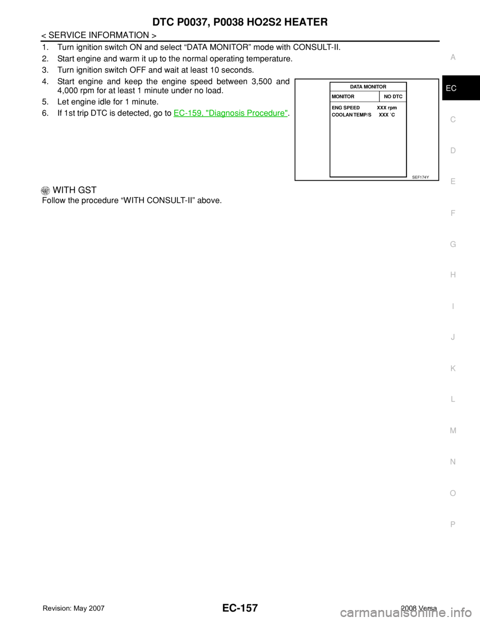
1. Turn ignition switch ON and select “DATA MONITOR” mode with CONSULT-II.
2. Start engine and warm it up to the normal operating temperature.
3. Turn ignition switch OFF and wait at least 10 seconds.
4. Start engine and keep the engine speed between 3,500 and
4,000 rpm for at least 1 minute under no load.
5. Let engine idle for 1 minute.
6. If 1st trip DTC is detected, go to EC-159, "
Diagnosis Procedure".
WITH GST
Follow the procedure “WITH CONSULT-II” above.
SEF174Y