fuel NISSAN TIIDA 2008 Service User Guide
[x] Cancel search | Manufacturer: NISSAN, Model Year: 2008, Model line: TIIDA, Model: NISSAN TIIDA 2008Pages: 2771, PDF Size: 60.61 MB
Page 866 of 2771
ON BOARD DIAGNOSTIC (OBD) SYSTEM
CVT-27
< SERVICE INFORMATION >
D
E
F
G
H
I
J
K
L
MA
B
CVT
N
O
P
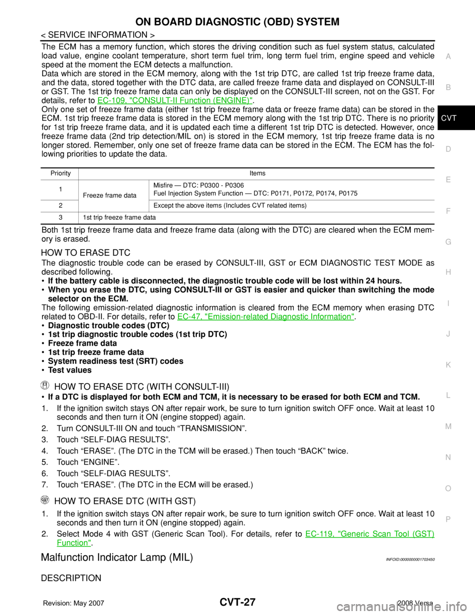
The ECM has a memory function, which stores the driving condition such as fuel system status, calculated
load value, engine coolant temperature, short term fuel trim, long term fuel trim, engine speed and vehicle
speed at the moment the ECM detects a malfunction.
Data which are stored in the ECM memory, along with the 1st trip DTC, are called 1st trip freeze frame data,
and the data, stored together with the DTC data, are called freeze frame data and displayed on CONSULT-III
or GST. The 1st trip freeze frame data can only be displayed on the CONSULT-III screen, not on the GST. For
details, refer to EC-109, "
CONSULT-II Function (ENGINE)".
Only one set of freeze frame data (either 1st trip freeze frame data or freeze frame data) can be stored in the
ECM. 1st trip freeze frame data is stored in the ECM memory along with the 1st trip DTC. There is no priority
for 1st trip freeze frame data, and it is updated each time a different 1st trip DTC is detected. However, once
freeze frame data (2nd trip detection/MIL on) is stored in the ECM memory, 1st trip freeze frame data is no
longer stored. Remember, only one set of freeze frame data can be stored in the ECM. The ECM has the fol-
lowing priorities to update the data.
Both 1st trip freeze frame data and freeze frame data (along with the DTC) are cleared when the ECM mem-
ory is erased.
HOW TO ERASE DTC
The diagnostic trouble code can be erased by CONSULT-III, GST or ECM DIAGNOSTIC TEST MODE as
described following.
•If the battery cable is disconnected, the diagnostic trouble code will be lost within 24 hours.
•When you erase the DTC, using CONSULT-III or GST is easier and quicker than switching the mode
selector on the ECM.
The following emission-related diagnostic information is cleared from the ECM memory when erasing DTC
related to OBD-II. For details, refer to EC-47, "
Emission-related Diagnostic Information".
•Diagnostic trouble codes (DTC)
•1st trip diagnostic trouble codes (1st trip DTC)
•Freeze frame data
•1st trip freeze frame data
•System readiness test (SRT) codes
•Test values
HOW TO ERASE DTC (WITH CONSULT-III)
•If a DTC is displayed for both ECM and TCM, it is necessary to be erased for both ECM and TCM.
1. If the ignition switch stays ON after repair work, be sure to turn ignition switch OFF once. Wait at least 10
seconds and then turn it ON (engine stopped) again.
2. Turn CONSULT-III ON and touch “TRANSMISSION”.
3. Touch “SELF-DIAG RESULTS”.
4. Touch “ERASE”. (The DTC in the TCM will be erased.) Then touch “BACK” twice.
5. Touch “ENGINE”.
6. Touch “SELF-DIAG RESULTS”.
7. Touch “ERASE”. (The DTC in the ECM will be erased.)
HOW TO ERASE DTC (WITH GST)
1. If the ignition switch stays ON after repair work, be sure to turn ignition switch OFF once. Wait at least 10
seconds and then turn it ON (engine stopped) again.
2. Select Mode 4 with GST (Generic Scan Tool). For details, refer to EC-119, "
Generic Scan Tool (GST)
Function".
Malfunction Indicator Lamp (MIL)INFOID:0000000001703450
DESCRIPTION
Priority Items
1
Freeze frame dataMisfire — DTC: P0300 - P0306
Fuel Injection System Function — DTC: P0171, P0172, P0174, P0175
2 Except the above items (Includes CVT related items)
3 1st trip freeze frame data
Page 874 of 2771
TROUBLE DIAGNOSIS
CVT-35
< SERVICE INFORMATION >
D
E
F
G
H
I
J
K
L
MA
B
CVT
N
O
P
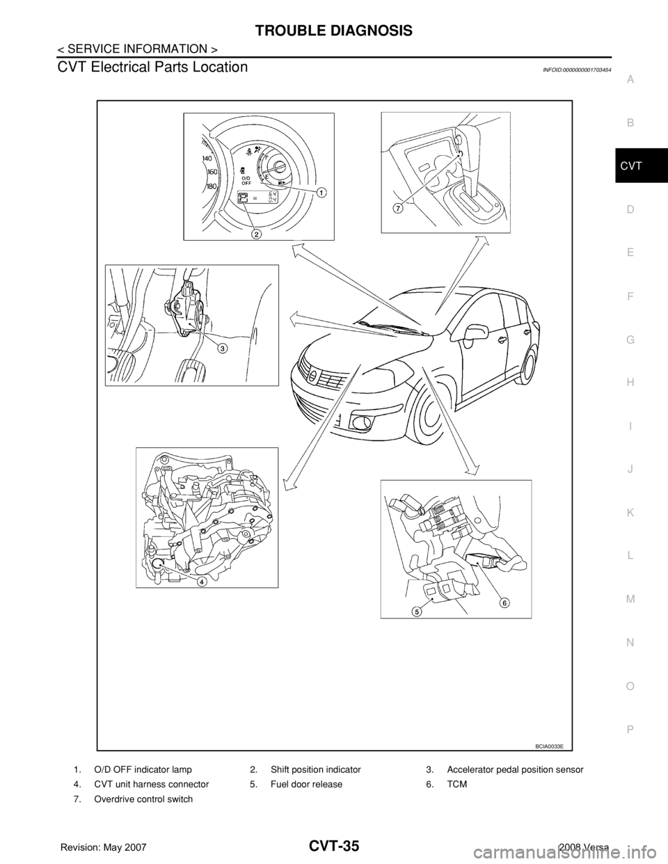
CVT Electrical Parts LocationINFOID:0000000001703454
1. O/D OFF indicator lamp 2. Shift position indicator 3. Accelerator pedal position sensor
4. CVT unit harness connector 5. Fuel door release 6. TCM
7. Overdrive control switch
BCIA0033E
Page 1022 of 2771

DI-1
ELECTRICAL
C
D
E
F
G
H
I
J
L
M
SECTION DI
A
B
DI
N
O
P
CONTENTS
DRIVER INFORMATION SYSTEM
SERVICE INFORMATION ............................2
PRECAUTION .....................................................2
Precaution for Supplemental Restraint System
(SRS) "AIR BAG" and "SEAT BELT PRE-TEN-
SIONER" ...................................................................
2
PREPARATION ...................................................3
Commercial Service Tool ..........................................3
COMBINATION METERS ...................................4
Component Parts and Harness Connector Loca-
tion ............................................................................
4
System Description ...................................................4
Arrangement of Combination Meter ..........................6
Internal Circuit ...........................................................7
Wiring Diagram - METER - .......................................8
Combination Meter Harness Connector Terminal
Layout .....................................................................
10
Terminal and Reference Value for Combination
Meter .......................................................................
10
Self-Diagnosis Mode of Combination Meter ............11
CONSULT-III Function (METER/M&A) ...................13
Trouble Diagnosis ...................................................14
Symptom Chart .......................................................15
Power Supply and Ground Circuit Inspection .........15
Vehicle Speed Signal Inspection .............................16
Engine Speed Signal Inspection .............................17
Fuel Level Sensor Signal Inspection .......................17
Fuel Gauge Fluctuates, Indicates Wrong Value, or
Varies ......................................................................
19
Fuel Gauge Does Not Move to Full-position ...........19
DTC [U1000] CAN Communication Circuit .............19
Electrical Component Inspection .............................19
Removal and Installation .........................................20
WARNING LAMPS .............................................21
Schematic ................................................................21
Wiring Diagram - WARN - .......................................22
Oil Pressure Warning Lamp Stays Off (Ignition
Switch ON) ..............................................................
30
Oil Pressure Warning Lamp Does Not Turn Off
(Oil Pressure Is Normal) ..........................................
32
Component Inspection .............................................32
A/T INDICATOR ................................................34
System Description ..................................................34
Wiring Diagram - AT/IND - .......................................35
A/T Indicator Does Not Illuminate ............................36
CVT INDICATOR ...............................................38
System Description ..................................................38
Wiring Diagram - CVTIND - .....................................38
CVT Indicator Does Not Illuminate ..........................39
WARNING CHIME .............................................41
Component Parts and Harness Connector Loca-
tion ...........................................................................
41
System Description ..................................................41
Wiring Diagram - CHIME - .......................................44
Terminal and Reference Value for BCM ..................45
CONSULT-III Function (BCM) .................................45
Trouble Diagnosis ....................................................46
Combination Meter Buzzer Circuit Inspection .........47
Front Door Switch LH Signal Inspection ..................48
Key Switch Signal Inspection (Without Intelligent
Key) .........................................................................
49
Key Switch and Ignition Knob Switch Signal In-
spection (With Intelligent Key, When Mechanical
Key Is Used) ............................................................
50
Lighting Switch Signal Inspection ............................52
Parking Brake Switch Signal Inspection ..................52
Electrical Component Inspection .............................53
Page 1025 of 2771
DI-4
< SERVICE INFORMATION >
COMBINATION METERS
COMBINATION METERS
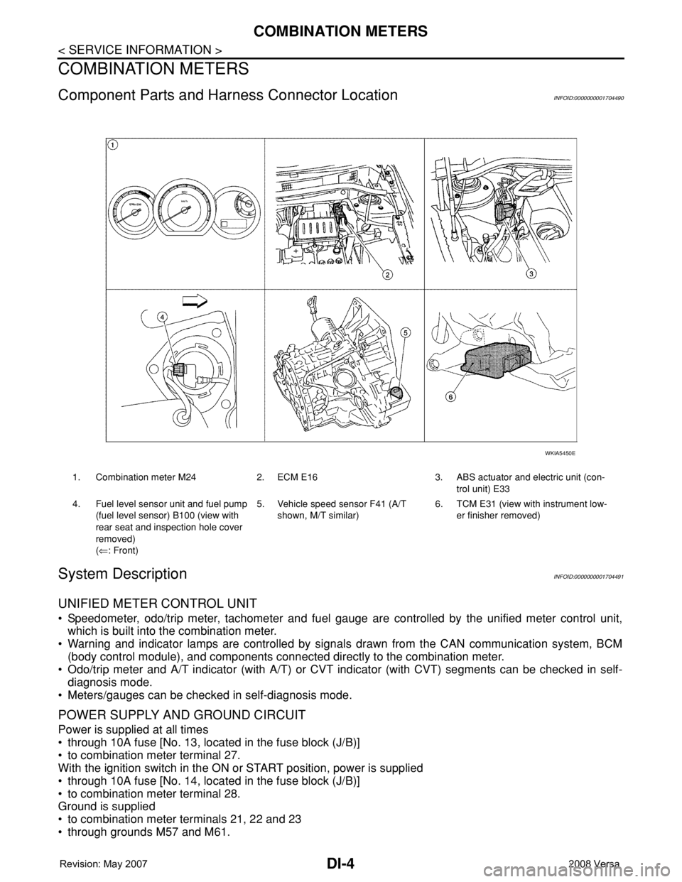
Component Parts and Harness Connector LocationINFOID:0000000001704490
System DescriptionINFOID:0000000001704491
UNIFIED METER CONTROL UNIT
• Speedometer, odo/trip meter, tachometer and fuel gauge are controlled by the unified meter control unit,
which is built into the combination meter.
• Warning and indicator lamps are controlled by signals drawn from the CAN communication system, BCM
(body control module), and components connected directly to the combination meter.
• Odo/trip meter and A/T indicator (with A/T) or CVT indicator (with CVT) segments can be checked in self-
diagnosis mode.
• Meters/gauges can be checked in self-diagnosis mode.
POWER SUPPLY AND GROUND CIRCUIT
Power is supplied at all times
• through 10A fuse [No. 13, located in the fuse block (J/B)]
• to combination meter terminal 27.
With the ignition switch in the ON or START position, power is supplied
• through 10A fuse [No. 14, located in the fuse block (J/B)]
• to combination meter terminal 28.
Ground is supplied
• to combination meter terminals 21, 22 and 23
• through grounds M57 and M61.
1. Combination meter M24 2. ECM E16 3. ABS actuator and electric unit (con-
trol unit) E33
4. Fuel level sensor unit and fuel pump
(fuel level sensor) B100 (view with
rear seat and inspection hole cover
removed)
(⇐: Front)5. Vehicle speed sensor F41 (A/T
shown, M/T similar)6. TCM E31 (view with instrument low-
er finisher removed)
WKIA5450E
Page 1026 of 2771
COMBINATION METERS
DI-5
< SERVICE INFORMATION >
C
D
E
F
G
H
I
J
L
MA
B
DI
N
O
P
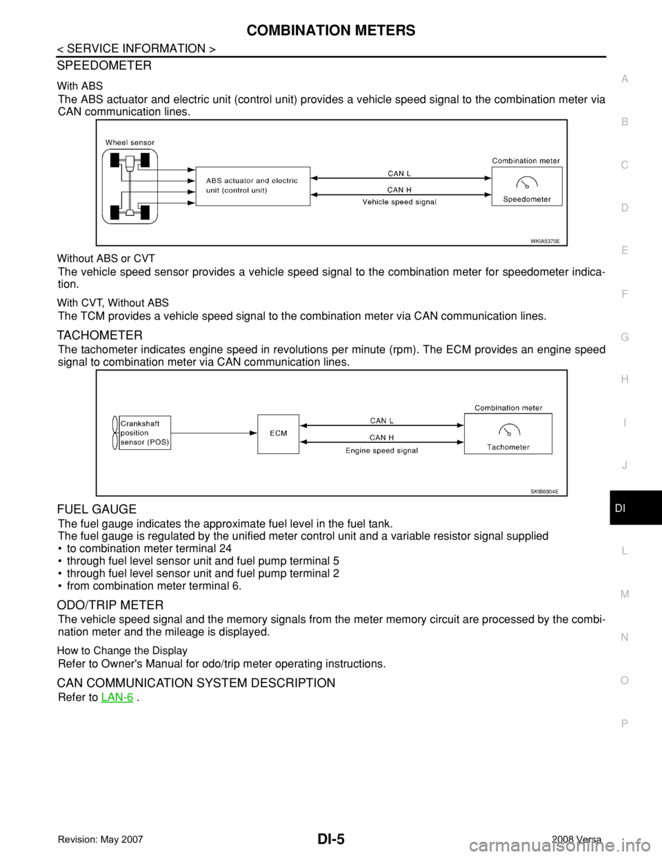
SPEEDOMETER
With ABS
The ABS actuator and electric unit (control unit) provides a vehicle speed signal to the combination meter via
CAN communication lines.
Without ABS or CVT
The vehicle speed sensor provides a vehicle speed signal to the combination meter for speedometer indica-
tion.
With CVT, Without ABS
The TCM provides a vehicle speed signal to the combination meter via CAN communication lines.
TACHOMETER
The tachometer indicates engine speed in revolutions per minute (rpm). The ECM provides an engine speed
signal to combination meter via CAN communication lines.
FUEL GAUGE
The fuel gauge indicates the approximate fuel level in the fuel tank.
The fuel gauge is regulated by the unified meter control unit and a variable resistor signal supplied
• to combination meter terminal 24
• through fuel level sensor unit and fuel pump terminal 5
• through fuel level sensor unit and fuel pump terminal 2
• from combination meter terminal 6.
ODO/TRIP METER
The vehicle speed signal and the memory signals from the meter memory circuit are processed by the combi-
nation meter and the mileage is displayed.
How to Change the Display
Refer to Owner's Manual for odo/trip meter operating instructions.
CAN COMMUNICATION SYSTEM DESCRIPTION
Refer to LAN-6 .
WKIA5370E
SKIB6904E
Page 1031 of 2771
DI-10
< SERVICE INFORMATION >
COMBINATION METERS
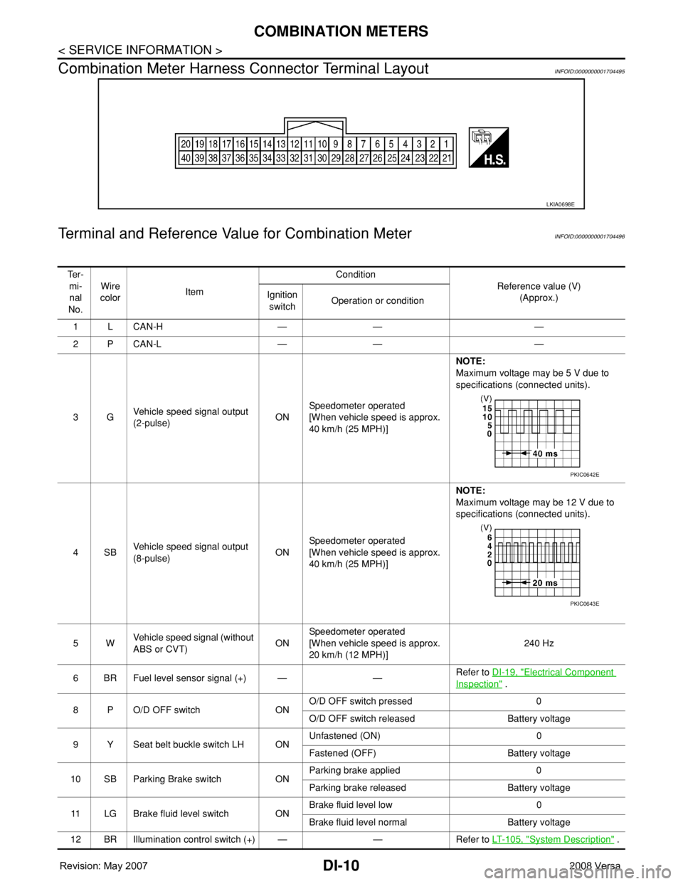
Combination Meter Harness Connector Terminal Layout
INFOID:0000000001704495
Terminal and Reference Value for Combination MeterINFOID:0000000001704496
LKIA0698E
Te r -
mi-
nal
No.Wire
colorItemCondition
Reference value (V)
(Approx.) Ignition
switchOperation or condition
1LCAN-H — — —
2PCAN-L — — —
3GVehicle speed signal output
(2-pulse)ONSpeedometer operated
[When vehicle speed is approx.
40 km/h (25 MPH)] NOTE:
Maximum voltage may be 5 V due to
specifications (connected units).
4SBVehicle speed signal output
(8-pulse)ONSpeedometer operated
[When vehicle speed is approx.
40 km/h (25 MPH)]NOTE:
Maximum voltage may be 12 V due to
specifications (connected units).
5WVehicle speed signal (without
ABS or CVT)ONSpeedometer operated
[When vehicle speed is approx.
20 km/h (12 MPH)]240 Hz
6 BR Fuel level sensor signal (+) — —Refer to DI-19, "
Electrical Component
Inspection" .
8 P O/D OFF switch ONO/D OFF switch pressed 0
O/D OFF switch released Battery voltage
9 Y Seat belt buckle switch LH ONUnfastened (ON) 0
Fastened (OFF) Battery voltage
10 SB Parking Brake switch ONParking brake applied 0
Parking brake released Battery voltage
11 LG Brake fluid level switch ONBrake fluid level low 0
Brake fluid level normal Battery voltage
12 BR Illumination control switch (+) — — Refer to LT- 1 0 5 , "
System Description" .
PKIC0642E
PKIC0643E
Page 1032 of 2771
COMBINATION METERS
DI-11
< SERVICE INFORMATION >
C
D
E
F
G
H
I
J
L
MA
B
DI
N
O
P
Self-Diagnosis Mode of Combination MeterINFOID:0000000001704497
SELF-DIAGNOSIS MODE FUNCTION
• Self-diagnosis can check for continuity between meter control circuit and each meter (speedometer, tachom-
eter and fuel gauge).
• Self-diagnosis can check for odo/trip meter and A/T indicator (with A/T) or CVT indicator (with CVT) seg-
ment, low-fuel level warning lamp, low water temperature indicator lamp, and high water temperature warn-
ing lamp.
OPERATION PROCEDURE
1. Turn the ignition switch ON, and switch the odo/trip meter to “trip A” or “trip B”.
NOTE:
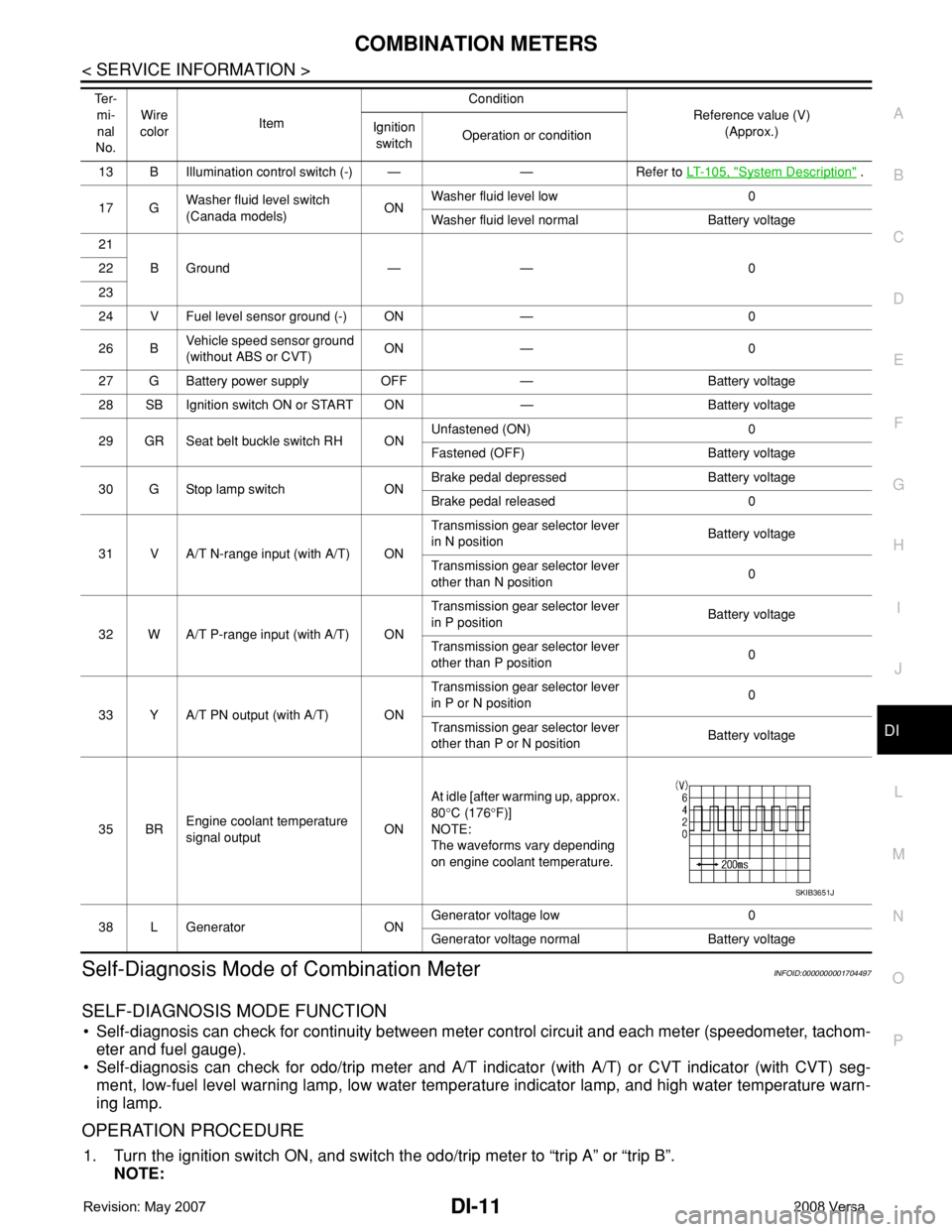
13 B Illumination control switch (-) — — Refer to LT- 1 0 5 , "System Description" .
17 GWasher fluid level switch
(Canada models)ONWasher fluid level low 0
Washer fluid level normal Battery voltage
21
BGround — — 0 22
23
24 V Fuel level sensor ground (-) ON — 0
26 BVehicle speed sensor ground
(without ABS or CVT)ON — 0
27 G Battery power supply OFF — Battery voltage
28 SB Ignition switch ON or START ON — Battery voltage
29 GR Seat belt buckle switch RH ONUnfastened (ON) 0
Fastened (OFF) Battery voltage
30 G Stop lamp switch ONBrake pedal depressed Battery voltage
Brake pedal released 0
31 V A/T N-range input (with A/T) ONTransmission gear selector lever
in N positionBattery voltage
Transmission gear selector lever
other than N position0
32 W A/T P-range input (with A/T) ONTransmission gear selector lever
in P positionBattery voltage
Transmission gear selector lever
other than P position0
33 Y A/T PN output (with A/T) ONTransmission gear selector lever
in P or N position0
Transmission gear selector lever
other than P or N positionBattery voltage
35 BREngine coolant temperature
signal outputONAt idle [after warming up, approx.
80°C (176°F)]
NOTE:
The waveforms vary depending
on engine coolant temperature.
38 L Generator ONGenerator voltage low 0
Generator voltage normal Battery voltage Te r -
mi-
nal
No.Wire
colorItemCondition
Reference value (V)
(Approx.) Ignition
switchOperation or condition
SKIB3651J
Page 1033 of 2771
DI-12
< SERVICE INFORMATION >
COMBINATION METERS
If the diagnosis function is activated with “trip A” displayed, the mileage on “trip A” will indicate “0000.0”,
but the actual trip mileage will be retained. (The same applies for “trip B”.)
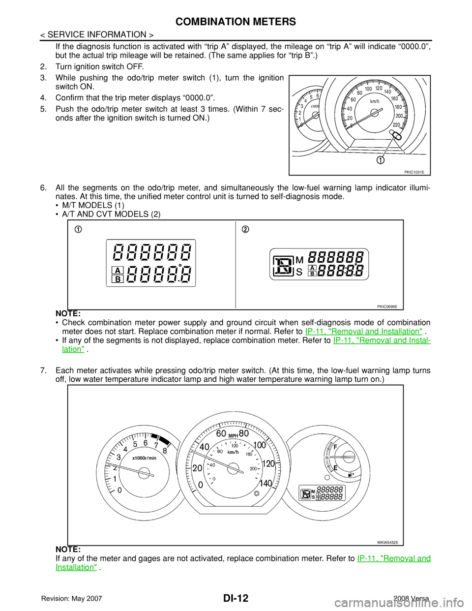
2. Turn ignition switch OFF.
3. While pushing the odo/trip meter switch (1), turn the ignition
switch ON.
4. Confirm that the trip meter displays “0000.0”.
5. Push the odo/trip meter switch at least 3 times. (Within 7 sec-
onds after the ignition switch is turned ON.)
6. All the segments on the odo/trip meter, and simultaneously the low-fuel warning lamp indicator illumi-
nates. At this time, the unified meter control unit is turned to self-diagnosis mode.
• M/T MODELS (1)
• A/T AND CVT MODELS (2)
NOTE:
• Check combination meter power supply and ground circuit when self-diagnosis mode of combination
meter does not start. Replace combination meter if normal. Refer to IP-11, "
Removal and Installation" .
• If any of the segments is not displayed, replace combination meter. Refer to IP-11, "
Removal and Instal-
lation" .
7. Each meter activates while pressing odo/trip meter switch. (At this time, the low-fuel warning lamp turns
off, low water temperature indicator lamp and high water temperature warning lamp turn on.)
NOTE:
If any of the meter and gages are not activated, replace combination meter. Refer to IP-11, "
Removal and
Installation" .
PKIC1031E
PKIC0699E
WKIA5452E
Page 1034 of 2771
COMBINATION METERS
DI-13
< SERVICE INFORMATION >
C
D
E
F
G
H
I
J
L
MA
B
DI
N
O
P
CONSULT-III Function (METER/M&A)INFOID:0000000001704498
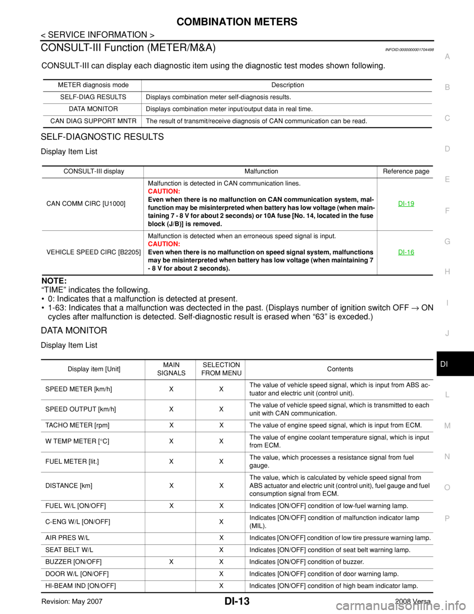
CONSULT-III can display each diagnostic item using the diagnostic test modes shown following.
SELF-DIAGNOSTIC RESULTS
Display Item List
NOTE:
“TIME” indicates the following.
• 0: Indicates that a malfunction is detected at present.
• 1-63: Indicates that a malfunction was dectected in the past. (Displays number of ignition switch OFF → ON
cycles after malfunction is detected. Self-diagnostic result is erased when “63” is exceded.)
DATA MONITOR
Display Item List
METER diagnosis mode Description
SELF-DIAG RESULTS Displays combination meter self-diagnosis results.
DATA MONITOR Displays combination meter input/output data in real time.
CAN DIAG SUPPORT MNTR The result of transmit/receive diagnosis of CAN communication can be read.
CONSULT-III display Malfunction Reference page
CAN COMM CIRC [U1000]Malfunction is detected in CAN communication lines.
CAUTION:
Even when there is no malfunction on CAN communication system, mal-
function may be misinterpreted when battery has low voltage (when main-
taining 7 - 8 V for about 2 seconds) or 10A fuse [No. 14, located in the fuse
block (J/B)] is removed.DI-19
VEHICLE SPEED CIRC [B2205]Malfunction is detected when an erroneous speed signal is input.
CAUTION:
Even when there is no malfunction on speed signal system, malfunctions
may be misinterpreted when battery has low voltage (when maintaining 7
- 8 V for about 2 seconds).DI-16
Display item [Unit]MAIN
SIGNALSSELECTION
FROM MENUContents
SPEED METER [km/h] X XThe value of vehicle speed signal, which is input from ABS ac-
tuator and electric unit (control unit).
SPEED OUTPUT [km/h] X XThe value of vehicle speed signal, which is transmitted to each
unit with CAN communication.
TACHO METER [rpm] X X The value of engine speed signal, which is input from ECM.
W TEMP METER [°C] X XThe value of engine coolant temperature signal, which is input
from ECM.
FUEL METER [lit.] X XThe value, which processes a resistance signal from fuel
gauge.
DISTANCE [km] X XThe value, which is calculated by vehicle speed signal from
ABS actuator and electric unit (control unit), fuel gauge and fuel
consumption signal from ECM.
FUEL W/L [ON/OFF] X X Indicates [ON/OFF] condition of low-fuel warning lamp.
C-ENG W/L [ON/OFF] XIndicates [ON/OFF] condition of malfunction indicator lamp
(MIL).
AIR PRES W/L X Indicates [ON/OFF] condition of low tire pressure warning lamp.
SEAT BELT W/L X Indicates [ON/OFF] condition of seat belt warning lamp.
BUZZER [ON/OFF] X X Indicates [ON/OFF] condition of buzzer.
DOOR W/L [ON/OFF] X Indicates [ON/OFF] condition of door warning lamp.
HI-BEAM IND [ON/OFF] X Indicates [ON/OFF] condition of high beam indicator lamp.
Page 1036 of 2771
COMBINATION METERS
DI-15
< SERVICE INFORMATION >
C
D
E
F
G
H
I
J
L
MA
B
DI
N
O
P
NO >> Check power supply and ground circuit of combination meter. Refer to DI-15, "Power Supply and
Ground Circuit Inspection" .
2.CHECK COMBINATION METER (CONSULT-III)
Select “METER/M&A” on CONSULT-III and perform self-diagnosis of combination meter. Refer to DI-13,
"CONSULT-III Function (METER/M&A)" .
Self
-diagnostic results content
No malfunction detected>> Refer to DI-15, "Symptom Chart" .
Malfunction detected>> Refer to DI-13, "
CONSULT-III Function (METER/M&A)" .
Symptom ChartINFOID:0000000001704500
Power Supply and Ground Circuit InspectionINFOID:0000000001704501
1.CHECK FUSE
Check for blown combination meter fuses.
OK or NG
OK >> GO TO 2.
NG >> Be sure to eliminate cause of malfunction before installing new fuse. Refer to PG-3
.
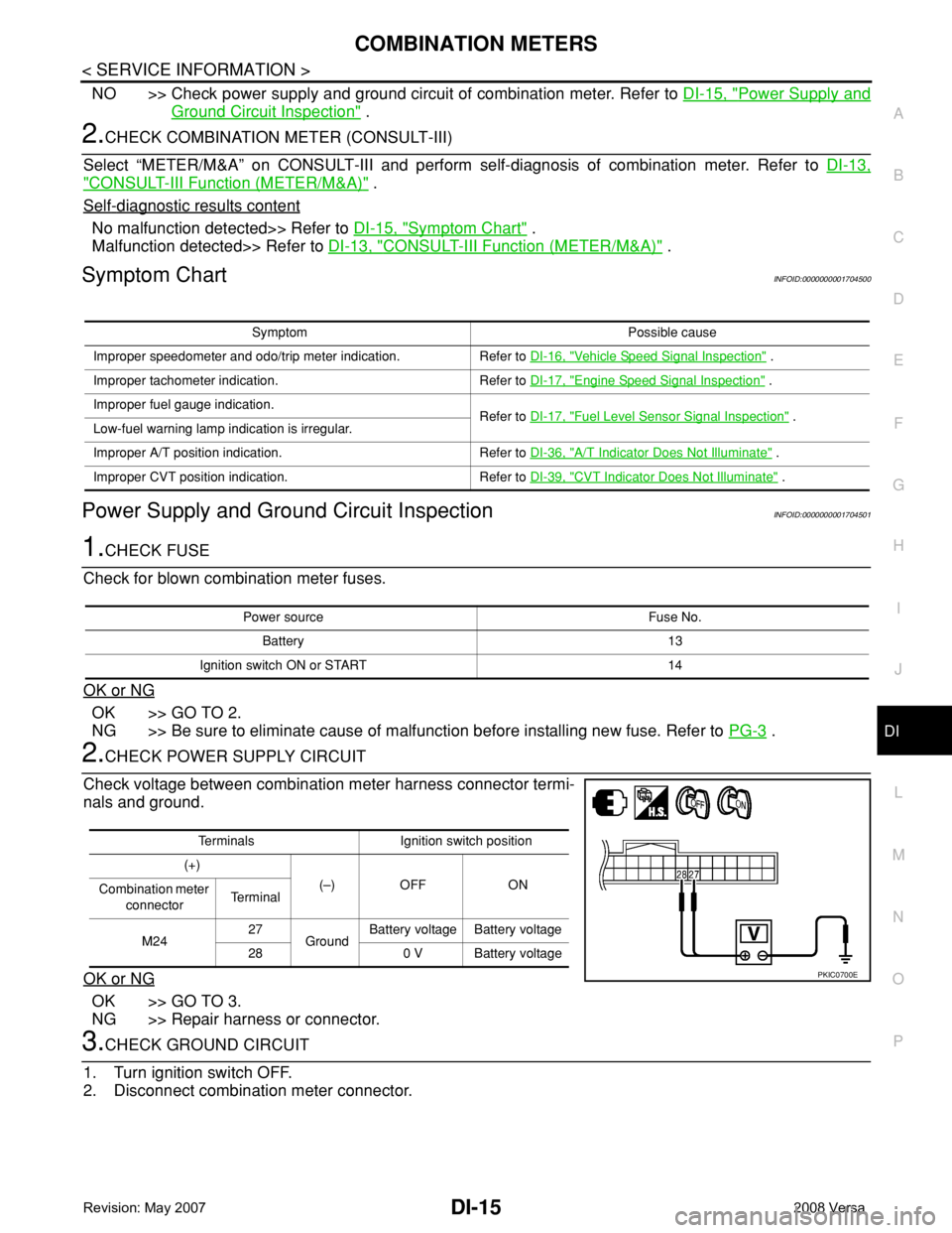
2.CHECK POWER SUPPLY CIRCUIT
Check voltage between combination meter harness connector termi-
nals and ground.
OK or NG
OK >> GO TO 3.
NG >> Repair harness or connector.
3.CHECK GROUND CIRCUIT
1. Turn ignition switch OFF.
2. Disconnect combination meter connector.
Symptom Possible cause
Improper speedometer and odo/trip meter indication. Refer to DI-16, "
Vehicle Speed Signal Inspection" .
Improper tachometer indication. Refer to DI-17, "
Engine Speed Signal Inspection" .
Improper fuel gauge indication.
Refer to DI-17, "
Fuel Level Sensor Signal Inspection" .
Low-fuel warning lamp indication is irregular.
Improper A/T position indication. Refer to DI-36, "
A/T Indicator Does Not Illuminate" .
Improper CVT position indication. Refer to DI-39, "
CVT Indicator Does Not Illuminate" .
Power source Fuse No.
Battery 13
Ignition switch ON or START 14
Terminals Ignition switch position
(+)
(–) OFF ON
Combination meter
connectorTe r m i n a l
M2427
GroundBattery voltage Battery voltage
28 0 V Battery voltage
PKIC0700E