fuel NISSAN TIIDA 2008 Service Workshop Manual
[x] Cancel search | Manufacturer: NISSAN, Model Year: 2008, Model line: TIIDA, Model: NISSAN TIIDA 2008Pages: 2771, PDF Size: 60.61 MB
Page 1121 of 2771
ON BOARD DIAGNOSTIC (OBD) SYSTEM
EC-47
< SERVICE INFORMATION >
C
D
E
F
G
H
I
J
K
L
MA
EC
N
P O
Therefore, when electrical controlled throttle and part of ECM related diagnoses are continuously detected as
NG for 5 trips, ECM warns the driver that engine control system malfunctions and MIL circuit is open by means
of operating fail-safe function.
The fail-safe function also operates when above diagnoses except MIL circuit are detected, and demands the
driver to repair the malfunction.
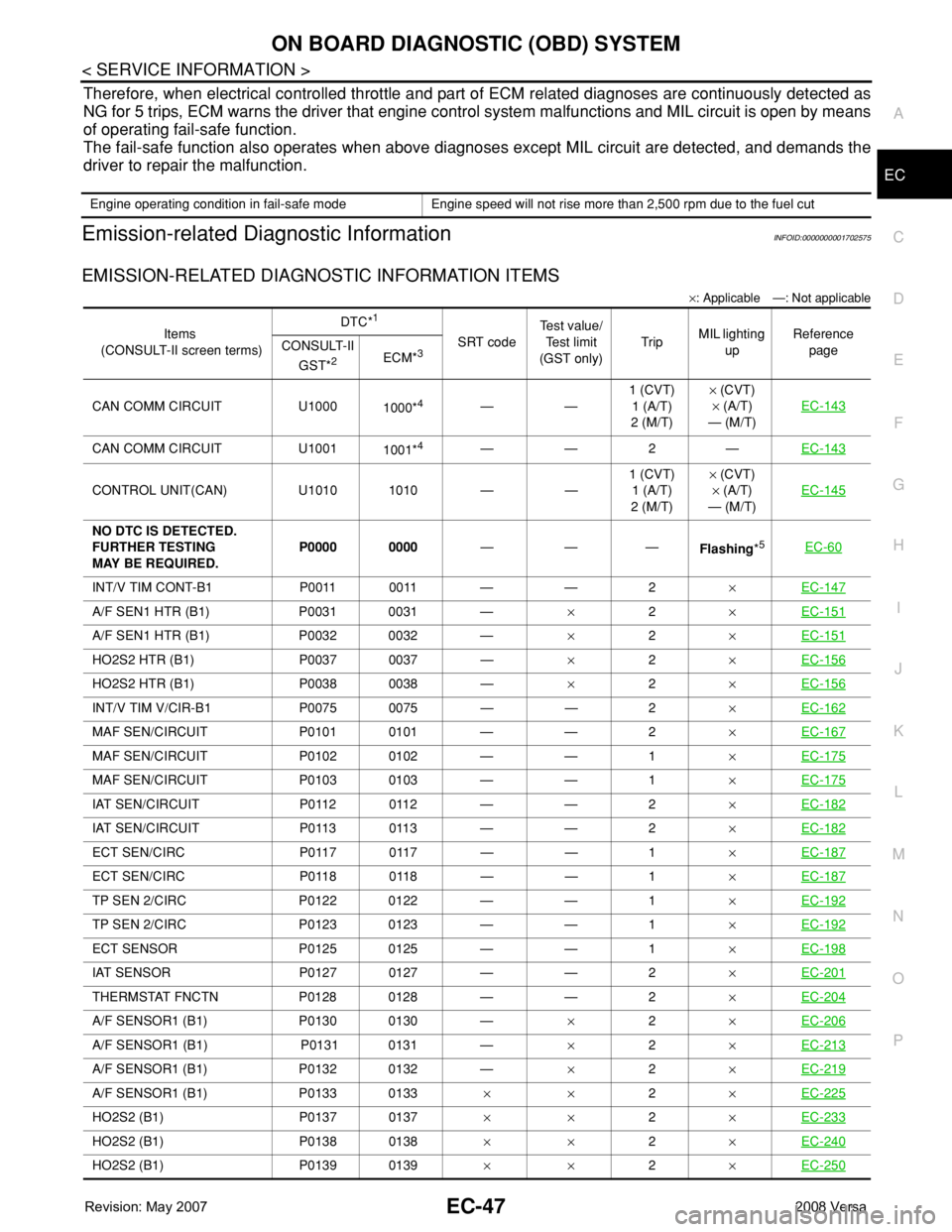
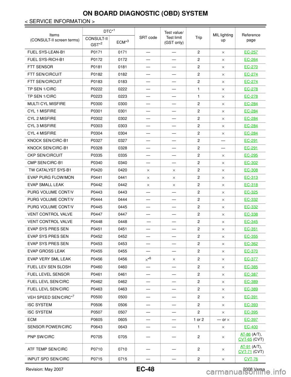
Emission-related Diagnostic InformationINFOID:0000000001702575
EMISSION-RELATED DIAGNOSTIC INFORMATION ITEMS
×: Applicable —: Not applicable
Engine operating condition in fail-safe mode Engine speed will not rise more than 2,500 rpm due to the fuel cut
Items
(CONSULT-II screen terms)DTC*
1
SRT codeTest value/
Test limit
(GST only)TripMIL lighting
upReference
page CONSULT-II
GST*
2ECM*3
CAN COMM CIRCUIT U1000
1000*4——1 (CVT)
1 (A/T)
2 (M/T)× (CVT)
× (A/T)
— (M/T)EC-143
CAN COMM CIRCUIT U1001
1001*4——2—EC-143
CONTROL UNIT(CAN) U1010 1010 — —1 (CVT)
1 (A/T)
2 (M/T)× (CVT)
× (A/T)
— (M/T)EC-145
NO DTC IS DETECTED.
FURTHER TESTING
MAY BE REQUIRED.P0000 0000———
Flashing*5EC-60
INT/V TIM CONT-B1 P0011 0011 — — 2×EC-147
A/F SEN1 HTR (B1) P0031 0031 —×2×EC-151
A/F SEN1 HTR (B1) P0032 0032 —×2×EC-151
HO2S2 HTR (B1) P0037 0037 —×2×EC-156
HO2S2 HTR (B1) P0038 0038 —×2×EC-156
INT/V TIM V/CIR-B1 P0075 0075 — — 2×EC-162
MAF SEN/CIRCUIT P0101 0101 — — 2×EC-167
MAF SEN/CIRCUIT P0102 0102 — — 1×EC-175
MAF SEN/CIRCUIT P0103 0103 — — 1×EC-175
IAT SEN/CIRCUIT P0112 0112 — — 2×EC-182
IAT SEN/CIRCUIT P0113 0113 — — 2×EC-182
ECT SEN/CIRC P0117 0117 — — 1×EC-187
ECT SEN/CIRC P0118 0118 — — 1×EC-187
TP SEN 2/CIRC P0122 0122 — — 1×EC-192
TP SEN 2/CIRC P0123 0123 — — 1×EC-192
ECT SENSOR P0125 0125 — — 1×EC-198
IAT SENSOR P0127 0127 — — 2×EC-201
THERMSTAT FNCTN P0128 0128 — — 2×EC-204
A/F SENSOR1 (B1) P0130 0130 —×2×EC-206
A/F SENSOR1 (B1) P0131 0131 —×2×EC-213
A/F SENSOR1 (B1) P0132 0132 —×2×EC-219
A/F SENSOR1 (B1) P0133 0133××2×EC-225
HO2S2 (B1) P0137 0137××2×EC-233
HO2S2 (B1) P0138 0138××2×EC-240
HO2S2 (B1) P0139 0139××2×EC-250
Page 1122 of 2771
EC-48
< SERVICE INFORMATION >
ON BOARD DIAGNOSTIC (OBD) SYSTEM
FUEL SYS-LEAN-B1 P0171 0171 — — 2×EC-257
FUEL SYS-RICH-B1 P0172 0172 — — 2×EC-264
FTT SENSOR P0181 0181 — — 2×EC-270
FTT SEN/CIRCUIT P0182 0182 — — 2×EC-274
FTT SEN/CIRCUIT P0183 0183 — — 2×EC-274
TP SEN 1/CIRC P0222 0222 — — 1×EC-278
TP SEN 1/CIRC P0223 0223 — — 1×EC-278
MULTI CYL MISFIRE P0300 0300 — — 2×EC-284
CYL 1 MISFIRE P0301 0301 — — 2×EC-284
CYL 2 MISFIRE P0302 0302 — — 2×EC-284
CYL 3 MISFIRE P0303 0303 — — 2×EC-284
CYL 4 MISFIRE P0304 0304 — — 2×EC-284
KNOCK SEN/CIRC-B1 P0327 0327 — — 2 —EC-291
KNOCK SEN/CIRC-B1 P0328 0328 — — 2 —EC-291
CKP SEN/CIRCUIT P0335 0335 — — 2×EC-295
CMP SEN/CIRC-B1 P0340 0340 — — 2×EC-302
TW CATALYST SYS-B1 P0420 0420× ×2×EC-308
EVAP PURG FLOW/MON P0441 0441××2×EC-313
EVAP SMALL LEAK P0442 0442××2×EC-318
PURG VOLUME CONT/V P0443 0443 — — 2×EC-325
PURG VOLUME CONT/V P0444 0444 — — 2×EC-332
PURG VOLUME CONT/V P0445 0445 — — 2×EC-332
VENT CONTROL VALVE P0447 0447 — — 2×EC-338
VENT CONTROL VALVE P0448 0448 — — 2×EC-345
EVAP SYS PRES SEN P0451 0451 — — 2×EC-351
EVAP SYS PRES SEN P0452 0452 — — 2×EC-355
EVAP SYS PRES SEN P0453 0453 — — 2×EC-362
EVAP GROSS LEAK P0455 0455 — — 2×EC-370
EVAP VERY SML LEAK P0456 0456
×*6×2×EC-377
FUEL LEV SEN SLOSH P0460 0460 — — 2×EC-385
FUEL LEVEL SENSOR P0461 0461 — — 2×EC-387
FUEL LEVL SEN/CIRC P0462 0462 — — 2×EC-389
FUEL LEVL SEN/CIRC P0463 0463 — — 2×EC-389
VEH SPEED SEN/CIRC*7P0500 0500 — — 2×EC-391
ISC SYSTEM P0506 0506 — — 2×EC-393
ISC SYSTEM P0507 0507 — — 2×EC-395
ECM P0605 0605 — — 1 or 2 — or ×EC-397
SENSOR POWER/CIRC P0643 0643 — — 1×EC-400
PNP SW/CIRC P0705 0705 — — 2×AT- 8 6 (A/T),
CVT-65
(CVT)
ATF TEMP SEN/CIRC P0710 0710 — — 2×AT- 9 1
(A/T),
CVT-71
(CVT)
INPUT SPD SEN/CIRC P0715 0715 — — 2×CVT-76
Items
(CONSULT-II screen terms)DTC*
1
SRT codeTest value/
Test limit
(GST only)TripMIL lighting
upReference
page CONSULT-II
GST*
2ECM*3
Page 1125 of 2771
ON BOARD DIAGNOSTIC (OBD) SYSTEM
EC-51
< SERVICE INFORMATION >
C
D
E
F
G
H
I
J
K
L
MA
EC
N
P O
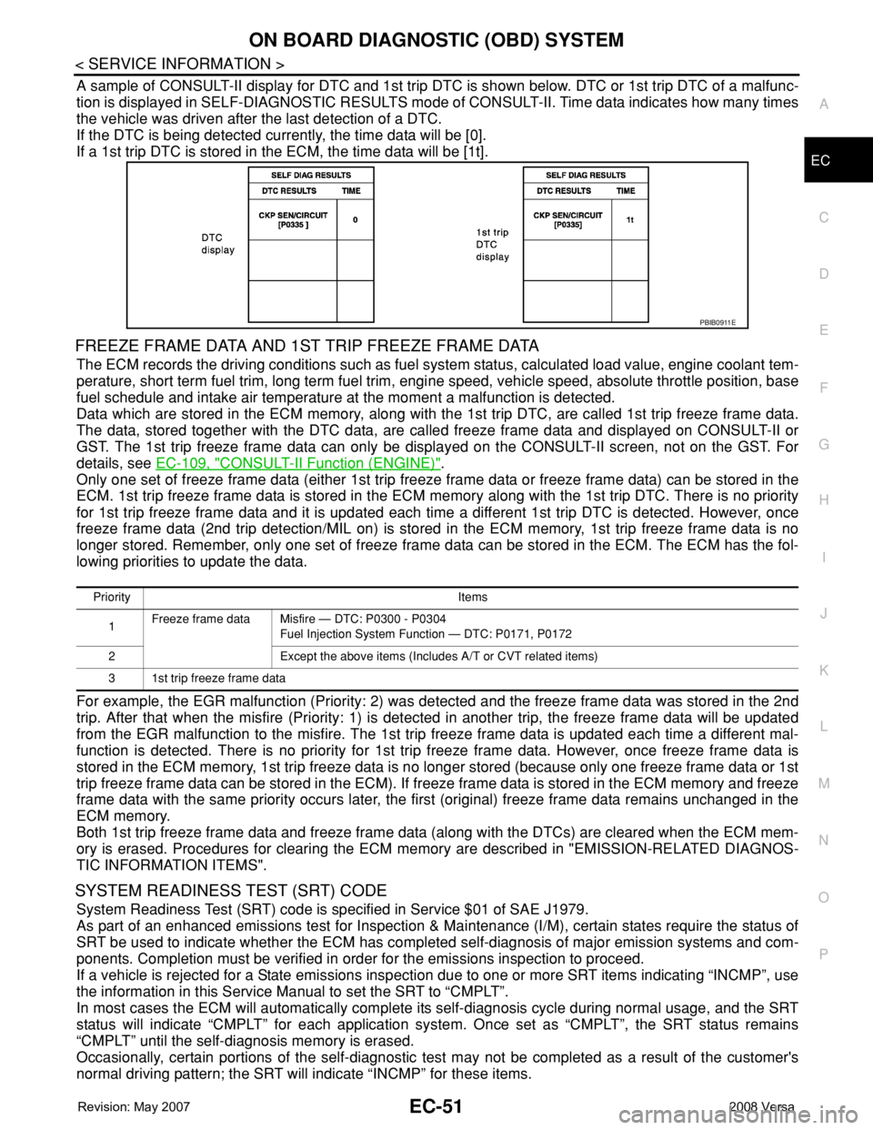
A sample of CONSULT-II display for DTC and 1st trip DTC is shown below. DTC or 1st trip DTC of a malfunc-
tion is displayed in SELF-DIAGNOSTIC RESULTS mode of CONSULT-II. Time data indicates how many times
the vehicle was driven after the last detection of a DTC.
If the DTC is being detected currently, the time data will be [0].
If a 1st trip DTC is stored in the ECM, the time data will be [1t].
FREEZE FRAME DATA AND 1ST TRIP FREEZE FRAME DATA
The ECM records the driving conditions such as fuel system status, calculated load value, engine coolant tem-
perature, short term fuel trim, long term fuel trim, engine speed, vehicle speed, absolute throttle position, base
fuel schedule and intake air temperature at the moment a malfunction is detected.
Data which are stored in the ECM memory, along with the 1st trip DTC, are called 1st trip freeze frame data.
The data, stored together with the DTC data, are called freeze frame data and displayed on CONSULT-II or
GST. The 1st trip freeze frame data can only be displayed on the CONSULT-II screen, not on the GST. For
details, see EC-109, "
CONSULT-II Function (ENGINE)".
Only one set of freeze frame data (either 1st trip freeze frame data or freeze frame data) can be stored in the
ECM. 1st trip freeze frame data is stored in the ECM memory along with the 1st trip DTC. There is no priority
for 1st trip freeze frame data and it is updated each time a different 1st trip DTC is detected. However, once
freeze frame data (2nd trip detection/MIL on) is stored in the ECM memory, 1st trip freeze frame data is no
longer stored. Remember, only one set of freeze frame data can be stored in the ECM. The ECM has the fol-
lowing priorities to update the data.
For example, the EGR malfunction (Priority: 2) was detected and the freeze frame data was stored in the 2nd
trip. After that when the misfire (Priority: 1) is detected in another trip, the freeze frame data will be updated
from the EGR malfunction to the misfire. The 1st trip freeze frame data is updated each time a different mal-
function is detected. There is no priority for 1st trip freeze frame data. However, once freeze frame data is
stored in the ECM memory, 1st trip freeze data is no longer stored (because only one freeze frame data or 1st
trip freeze frame data can be stored in the ECM). If freeze frame data is stored in the ECM memory and freeze
frame data with the same priority occurs later, the first (original) freeze frame data remains unchanged in the
ECM memory.
Both 1st trip freeze frame data and freeze frame data (along with the DTCs) are cleared when the ECM mem-
ory is erased. Procedures for clearing the ECM memory are described in "EMISSION-RELATED DIAGNOS-
TIC INFORMATION ITEMS".
SYSTEM READINESS TEST (SRT) CODE
System Readiness Test (SRT) code is specified in Service $01 of SAE J1979.
As part of an enhanced emissions test for Inspection & Maintenance (I/M), certain states require the status of
SRT be used to indicate whether the ECM has completed self-diagnosis of major emission systems and com-
ponents. Completion must be verified in order for the emissions inspection to proceed.
If a vehicle is rejected for a State emissions inspection due to one or more SRT items indicating “INCMP”, use
the information in this Service Manual to set the SRT to “CMPLT”.
In most cases the ECM will automatically complete its self-diagnosis cycle during normal usage, and the SRT
status will indicate “CMPLT” for each application system. Once set as “CMPLT”, the SRT status remains
“CMPLT” until the self-diagnosis memory is erased.
Occasionally, certain portions of the self-diagnostic test may not be completed as a result of the customer's
normal driving pattern; the SRT will indicate “INCMP” for these items.
PBIB0911E
Priority Items
1Freeze frame data Misfire — DTC: P0300 - P0304
Fuel Injection System Function — DTC: P0171, P0172
2 Except the above items (Includes A/T or CVT related items)
3 1st trip freeze frame data
Page 1126 of 2771

EC-52
< SERVICE INFORMATION >
ON BOARD DIAGNOSTIC (OBD) SYSTEM
NOTE:
The SRT will also indicate “INCMP” if the self-diagnosis memory is erased for any reason or if the ECM mem-
ory power supply is interrupted for several hours.
If, during the state emissions inspection, the SRT indicates “CMPLT” for all test items, the inspector will con-
tinue with the emissions test. However, if the SRT indicates “INCMP” for one or more of the SRT items the
vehicle is returned to the customer untested.
NOTE:
If MIL is ON during the state emissions inspection, the vehicle is also returned to the customer untested even
though the SRT indicates “CMPLT” for all test items. Therefore, it is important to check SRT (“CMPLT”) and
DTC (No DTCs) before the inspection.
SRT Item
The table below shows required self-diagnostic items to set the SRT to “CMPLT”.
*: If completion of several SRTs is required, perform driving patterns (DTC confirmation procedure), one by one based on the priority for
models with CONSULT-II.
SRT Set Timing
SRT is set as “CMPLT” after self-diagnosis has been performed one or more times. Completion of SRT is
done regardless of whether the result is OK or NG. The set timing is different between OK and NG results and
is shown in the table below.
OK: Self-diagnosis is carried out and the result is OK.
NG: Self-diagnosis is carried out and the result is NG.SRT item
(CONSULT-II indication)Perfor-
mance
Priority*Required self-diagnostic items to set the SRT to “CMPLT” Corresponding DTC No.
CATALYST 2 Three way catalyst function P0420
EVAP SYSTEM 2 EVAP control system purge flow monitoring P0441
1 EVAP control system P0442
2 EVAP control system P0456
HO2S 2 Air fuel ratio (A/F) sensor 1 P0133
Heated oxygen sensor 2 P0137
Heated oxygen sensor 2 P0138
Heated oxygen sensor 2 P0139
Self-diagnosis resultExample
DiagnosisIgnition cycle
← ON → OFF ← ON → OFF ← ON → OFF ← ON →
All OK Case 1 P0400 OK (1) — (1) OK (2) — (2)
P0402 OK (1) — (1) — (1) OK (2)
P1402 OK (1) OK (2) — (2) — (2)
SRT of EGR “CMPLT” “CMPLT” “CMPLT” “CMPLT”
Case 2 P0400 OK (1) — (1) — (1) — (1)
P0402 — (0) — (0) OK (1) — (1)
P1402 OK (1) OK (2) — (2) — (2)
SRT of EGR “INCMP” “INCMP” “CMPLT” “CMPLT”
NG exists Case 3 P0400 OK OK — —
P0402 — — — —
P1402 NG — NGNG
(Consecutive
NG)
(1st trip)
DTC1st trip DTC — 1st trip DTCDTC
(= MIL “ON”)
SRT of EGR “INCMP” “INCMP” “INCMP” “CMPLT”
Page 1131 of 2771
ON BOARD DIAGNOSTIC (OBD) SYSTEM
EC-57
< SERVICE INFORMATION >
C
D
E
F
G
H
I
J
K
L
MA
EC
N
P O
• Sea level
• Flat road
• Ambient air temperature: 20 - 30°C (68 - 86°F)
• Diagnosis is performed as quickly as possible under normal conditions.
Under different conditions [For example: ambient air temperature other than 20 - 30°C (68 - 86°F)], diagno-
sis may also be performed.
Pattern 1:
•The engine is started at the engine coolant temperature of −10 to 35°C (14 to 95°F)
(where the voltage between the ECM terminal 38 and ground is 3.0 - 4.3V).
•The engine must be operated at idle speed until the engine coolant temperature is greater than 70°C
(158°F) (where the voltage between the ECM terminal 38 and ground is lower than 1.4V).
•The engine is started at the fuel tank temperature of warmer than 0°C (32°F) (where the voltage
between the ECM terminal 43 and ground is less than 4.1V).
Pattern 2:
• When steady-state driving is performed again even after it is interrupted, each diagnosis can be conducted.
In this case, the time required for diagnosis may be extended.
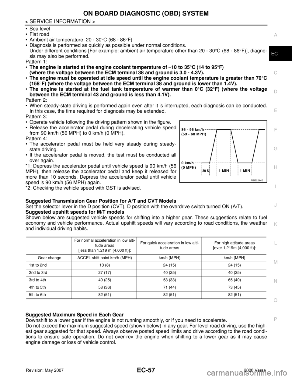
Pattern 3:
• Operate vehicle following the driving pattern shown in the figure.
• Release the accelerator pedal during decelerating vehicle speed
from 90 km/h (56 MPH) to 0 km/h (0 MPH).
Pattern 4:
• The accelerator pedal must be held very steady during steady-
state driving.
• If the accelerator pedal is moved, the test must be conducted all
over again.
*1: Depress the accelerator pedal until vehicle speed is 90 km/h (56
MPH), then release the accelerator pedal and keep it released for
more than 10 seconds. Depress the accelerator pedal until vehicle
speed is 90 km/h (56 MPH) again.
*2: Checking the vehicle speed with GST is advised.
Suggested Transmission Gear Position for A/T and CVT Models
Set the selector lever in the D position (CVT), D position with the overdrive switch turned ON (A/T).
Suggested upshift speeds for M/T models
Shown below are suggested vehicle speeds for shifting into a higher gear. These suggestions relate to fuel
economy and vehicle performance. Actual upshift speeds will vary according to road conditions, the weather
and individual driving habits.
Suggested Maximum Speed in Each Gear
Downshift to a lower gear if the engine is not running smoothly, or if you need to accelerate.
Do not exceed the maximum suggested speed (shown below) in any gear. For level road driving, use the high-
est gear suggested for that speed. Always observe posted speed limits and drive according to the road condi-
tions to ensure safe operation. Do not over-rev the engine when shifting to a lower gear as it may cause
engine damage or loss of vehicle control.
PBIB2244E
For normal acceleration in low alti-
tude areas
[less than 1,219 m (4,000 ft)]:For quick acceleration in low alti-
tude areasFor high attitude areas
[over 1,219m (4,000 ft)]:
Gear change ACCEL shift point km/h (MPH) km/h (MPH) km/h (MPH)
1st to 2nd 13 (8) 24 (15) 24 (15)
2nd to 3rd 27 (17) 40 (25) 40 (25)
3rd to 4th 40 (25) 53 (33) 65 (40)
4th to 5th 58 (36) 71 (44) 73 (45)
5th to 6th 82 (51) 82 (51) 82 (51)
Page 1132 of 2771

EC-58
< SERVICE INFORMATION >
ON BOARD DIAGNOSTIC (OBD) SYSTEM
TEST VALUE AND TEST LIMIT (GST ONLY — NOT APPLICABLE TO CONSULT-II)
The following is the information specified in Service $06 of SAE J1979.
The test value is a parameter used to determine whether a system/circuit diagnostic test is OK or NG while
being monitored by the ECM during self-diagnosis. The test limit is a reference value which is specified as the
maximum or minimum value and is compared with the test value being monitored.
These data (test value and test limit) are specified by Test ID (TID) and Component ID (CID) and can be dis-
played on the GST screen.
HOW TO ERASE EMISSION-RELATED DIAGNOSTIC INFORMATION
How to Erase DTC
With CONSULT-II
The emission related diagnostic information in the ECM can be erased by selecting “ERASE” in the “SELF-
DIAG RESULTS” mode with CONSULT-II.
If DTCs are displayed for both ECM and TCM (Transmission control module), they need to be erased individu-
ally from the ECM and TCM (Transmission control module).
NOTE:
If the DTC is not for A/T or CVT related items (see EC-9
), skip steps 2 through 4.
Gear km/h (MPH)
1st 50 (30)
2nd 90 (55)
3rd —
4th —
5th —
6th —
Item Self-diagnostic test item DTCTest value (GST display)
Test limit Conversion
TID CID
CATALYST Three way catalyst functionP0420 01H 81H Min. 1/128
P0420 02H 81H Min. 1
EVAP
SYSTEMEVAP control system (Small leak) P0442 05H 03H Max.
1/128 mm
2
EVAP control system purge flow monitoring P0441 06H 83H Min. 20 mV
EVAP control system (Very small leak) P0456 07H 03H Max.
1/128 mm
2
HO2SAir fuel ratio (A/F) sensor 1P0131 41H 8EH Min. 5 mV
P0132 42H 0EH Max. 5 mV
P2A00 43H 0EH Max. 0.002
P2A00 44H 8EH Min. 0.002
P0130 46H 0EH Max. 5 mV
P0130 47H 8EH Min. 5 mV
P0133 45H 8EH Min. 0.004
P0133 48H 8EH Min. 0.004
Heated oxygen sensor 2P0139 19H 86H Min. 10mV/500 ms
P0137 1AH 86H Min. 10 mV
P0138 1BH 06H Max. 10 mV
P0138 1CH 06H Max. 10 mV
HO2S HTRAir fuel ratio (A/F) sensor 1 heaterP0032 57H 10H Max. 5 mV
P0031 58H 90H Min. 5 mV
Heated oxygen sensor 2 heaterP0038 2DH 0AH Max. 20 mV
P0037 2EH 8AH Min. 20 mV
Page 1135 of 2771
ON BOARD DIAGNOSTIC (OBD) SYSTEM
EC-61
< SERVICE INFORMATION >
C
D
E
F
G
H
I
J
K
L
MA
EC
N
P O
When there is an open circuit on MIL circuit, the ECM cannot warn the driver by MIL lighting up when there is
malfunction on engine control system.
Therefore, when electrical controlled throttle and part of ECM related diagnoses are continuously detected as
NG for 5 trips, ECM warns the driver that engine control system malfunctions and MIL circuit is open by means
of operating fail-safe function.
The fail-safe function also operates when above diagnoses except MIL circuit are detected, and demands the
driver to repair the malfunction.
MIL Flashing Without DTC
When any SRT codes are not set, MIL may flash without DTC. For the details, refer to EC-47, "Emission-
related Diagnostic Information".
HOW TO SWITCH DIAGNOSTIC TEST MODE
NOTE:
•It is better to count the time accurately with a clock.
•It is impossible to switch the diagnostic mode when an accelerator pedal position sensor circuit has
a malfunction.
•Always ECM returns to Diagnostic Test Mode I after ignition switch is turned OFF.
How to Set Diagnostic Test Mode II (Self-diagnostic Results)
1. Confirm that accelerator pedal is fully released, turn ignition switch ON and wait 3 seconds.
2. Repeat the following procedure quickly five times within 5 seconds.
a. Fully depress the accelerator pedal.
b. Fully release the accelerator pedal.
3. Wait 7 seconds, fully depress the accelerator pedal and keep it for approx. 10 seconds until the MIL starts
blinking.
4. Fully release the accelerator pedal.
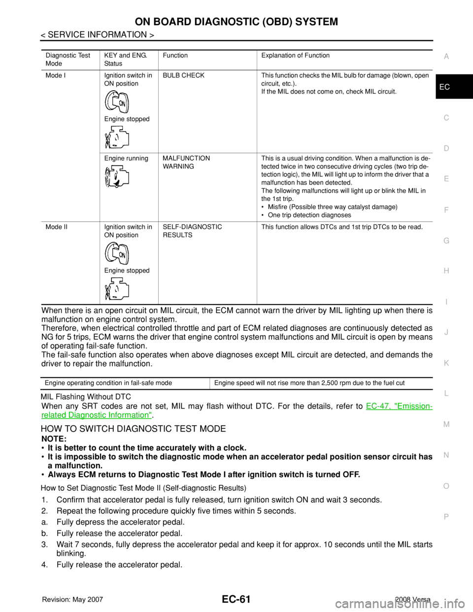
Diagnostic Test
ModeKEY and ENG.
Sta tusFunction Explanation of Function
Mode I Ignition switch in
ON position
Engine stoppedBULB CHECK This function checks the MIL bulb for damage (blown, open
circuit, etc.).
If the MIL does not come on, check MIL circuit.
Engine running MALFUNCTION
WARNINGThis is a usual driving condition. When a malfunction is de-
tected twice in two consecutive driving cycles (two trip de-
tection logic), the MIL will light up to inform the driver that a
malfunction has been detected.
The following malfunctions will light up or blink the MIL in
the 1st trip.
• Misfire (Possible three way catalyst damage)
• One trip detection diagnoses
Mode II Ignition switch in
ON position
Engine stoppedSELF-DIAGNOSTIC
RESULTSThis function allows DTCs and 1st trip DTCs to be read.
Engine operating condition in fail-safe mode Engine speed will not rise more than 2,500 rpm due to the fuel cut
Page 1137 of 2771
ON BOARD DIAGNOSTIC (OBD) SYSTEM
EC-63
< SERVICE INFORMATION >
C
D
E
F
G
H
I
J
K
L
MA
EC
N
P O
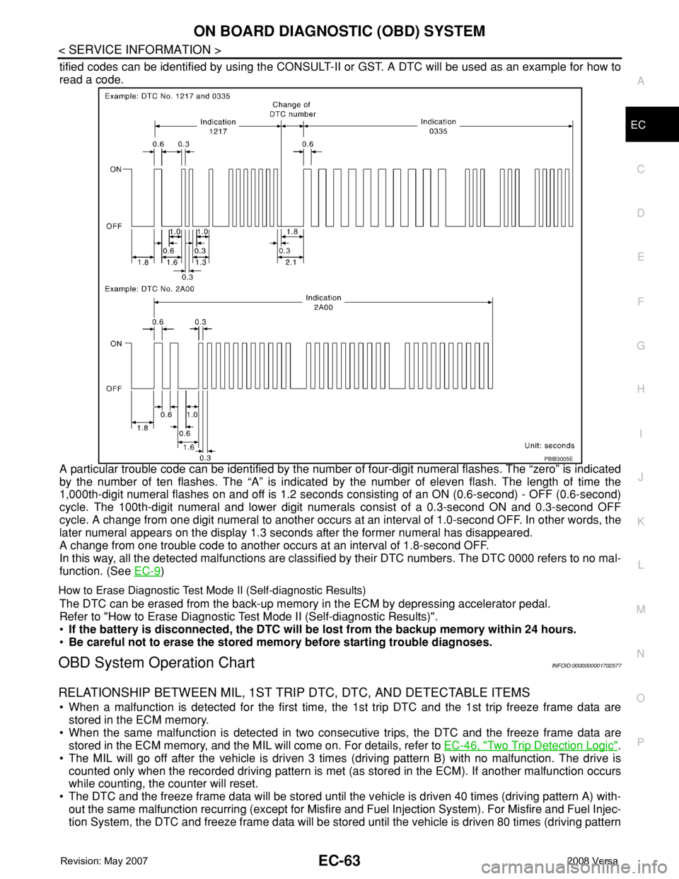
tified codes can be identified by using the CONSULT-II or GST. A DTC will be used as an example for how to
read a code.
A particular trouble code can be identified by the number of four-digit numeral flashes. The “zero” is indicated
by the number of ten flashes. The “A” is indicated by the number of eleven flash. The length of time the
1,000th-digit numeral flashes on and off is 1.2 seconds consisting of an ON (0.6-second) - OFF (0.6-second)
cycle. The 100th-digit numeral and lower digit numerals consist of a 0.3-second ON and 0.3-second OFF
cycle. A change from one digit numeral to another occurs at an interval of 1.0-second OFF. In other words, the
later numeral appears on the display 1.3 seconds after the former numeral has disappeared.
A change from one trouble code to another occurs at an interval of 1.8-second OFF.
In this way, all the detected malfunctions are classified by their DTC numbers. The DTC 0000 refers to no mal-
function. (See EC-9
)
How to Erase Diagnostic Test Mode II (Self-diagnostic Results)
The DTC can be erased from the back-up memory in the ECM by depressing accelerator pedal.
Refer to "How to Erase Diagnostic Test Mode II (Self-diagnostic Results)".
•If the battery is disconnected, the DTC will be lost from the backup memory within 24 hours.
•Be careful not to erase the stored memory before starting trouble diagnoses.
OBD System Operation ChartINFOID:0000000001702577
RELATIONSHIP BETWEEN MIL, 1ST TRIP DTC, DTC, AND DETECTABLE ITEMS
• When a malfunction is detected for the first time, the 1st trip DTC and the 1st trip freeze frame data are
stored in the ECM memory.
• When the same malfunction is detected in two consecutive trips, the DTC and the freeze frame data are
stored in the ECM memory, and the MIL will come on. For details, refer to EC-46, "
Two Trip Detection Logic".
• The MIL will go off after the vehicle is driven 3 times (driving pattern B) with no malfunction. The drive is
counted only when the recorded driving pattern is met (as stored in the ECM). If another malfunction occurs
while counting, the counter will reset.
• The DTC and the freeze frame data will be stored until the vehicle is driven 40 times (driving pattern A) with-
out the same malfunction recurring (except for Misfire and Fuel Injection System). For Misfire and Fuel Injec-
tion System, the DTC and freeze frame data will be stored until the vehicle is driven 80 times (driving pattern
PBIB3005E
Page 1138 of 2771

EC-64
< SERVICE INFORMATION >
ON BOARD DIAGNOSTIC (OBD) SYSTEM
C) without the same malfunction recurring. The “TIME” in “SELF-DIAGNOSTIC RESULTS” mode of CON-
SULT-II will count the number of times the vehicle is driven.
• The 1st trip DTC is not displayed when the self-diagnosis results in OK for the 2nd trip.
SUMMARY CHART
For details about patterns B and C under “Fuel Injection System” and “Misfire”, see "EXPLANATION FOR DRIVING PATTERNS FOR
“MISFIRE
For details about patterns A and B under “Other”, see "EXPLANATION FOR DRIVING PATTERNS FOR “MISFIRE
*1: Clear timing is at the moment OK is detected.
*2: Clear timing is when the same malfunction is detected in the 2nd trip.
RELATIONSHIP BETWEEN MIL, DTC, 1ST TRIP DTC AND DRIVING PATTERNS FOR “MISFIRE
Items Fuel Injection System Misfire Other
MIL (goes off) 3 (pattern B) 3 (pattern B) 3 (pattern B)
DTC, Freeze Frame Data (no
display)80 (pattern C) 80 (pattern C) 40 (pattern A)
1st Trip DTC (clear) 1 (pattern C), *1 1 (pattern C), *1 1 (pattern B)
1st Trip Freeze Frame Data
(clear)*1, *2 *1, *2 1 (pattern B)
Page 1139 of 2771
ON BOARD DIAGNOSTIC (OBD) SYSTEM
EC-65
< SERVICE INFORMATION >
C
D
E
F
G
H
I
J
K
L
MA
EC
N
P O
EXPLANATION FOR DRIVING PATTERNS FOR “MISFIRE
Driving pattern B means the vehicle operation as follows:
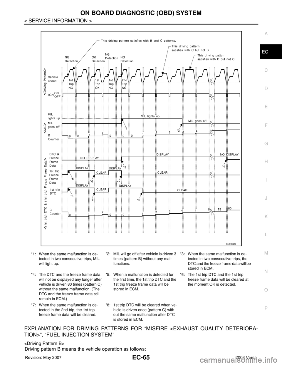
*1: When the same malfunction is de-
tected in two consecutive trips, MIL
will light up.*2: MIL will go off after vehicle is driven 3
times (pattern B) without any mal-
functions.*3: When the same malfunction is de-
tected in two consecutive trips, the
DTC and the freeze frame data will be
stored in ECM.
*4: The DTC and the freeze frame data
will not be displayed any longer after
vehicle is driven 80 times (pattern C)
without the same malfunction. (The
DTC and the freeze frame data still
remain in ECM.)*5: When a malfunction is detected for
the first time, the 1st trip DTC and the
1st trip freeze frame data will be
stored in ECM.*6: The 1st trip DTC and the 1st trip
freeze frame data will be cleared at
the moment OK is detected.
*7: When the same malfunction is de-
tected in the 2nd trip, the 1st trip
freeze frame data will be cleared.*8: 1st trip DTC will be cleared when ve-
hicle is driven once (pattern C) with-
out the same malfunction after DTC
is stored in ECM.
SEF392S