fuel NISSAN TIIDA 2008 Service Owner's Manual
[x] Cancel search | Manufacturer: NISSAN, Model Year: 2008, Model line: TIIDA, Model: NISSAN TIIDA 2008Pages: 2771, PDF Size: 60.61 MB
Page 1038 of 2771
COMBINATION METERS
DI-17
< SERVICE INFORMATION >
C
D
E
F
G
H
I
J
L
MA
B
DI
N
O
P
OK or NG
OK >> Check harness or connector between combination meter and vehicle speed sensor.
NG >> Replace vehicle speed sensor.
WITH CVT, WITHOUT ABS
1.CHECK COMBINATION METER INPUT SIGNAL
1. Start engine and select “METER/M&A” on CONSULT-III.
2. Using “SPEED METER” on “DATA MONITOR”, compare the value of “DATA MONITOR” with speedome-
ter pointer of combination meter.
OK or NG
OK >> Perform TCM self-diagnosis. Refer to CVT-47, "CONSULT-III Function (TRANSMISSION)" .
NG >> Replace combination meter. Refer to IP-11, "
Removal and Installation" .
Engine Speed Signal InspectionINFOID:0000000001704503
Symptom: Improper tachometer indication.
1.CHECK COMBINATION METER INPUT SIGNAL
1. Start engine and select “METER/M&A” on CONSULT-III.
2. Using “TACHO METER” on “DATA MONITOR”, compare the value of “DATA MONITOR” with tachometer
pointer of combination meter.
OK or NG
OK >> Perform ECM self-diagnosis. Refer to EC-109, "CONSULT-II Function (ENGINE)" .
NG >> Replace combination meter. Refer to IP-11, "
Removal and Installation" .
Fuel Level Sensor Signal InspectionINFOID:0000000001704504
Symptom:
• Improper fuel gauge indication.
• Low-fuel warning lamp indication is irregular.
NOTE:
The following symptoms do not indicate a malfunction.
• Depending on vehicle position or driving circumstance, the fuel level in the tank shifts and the indication may
fluctuate.
• If the vehicle is fueled with the ignition switch ON, the indication will update slowly.
• If the vehicle is tilted when the ignition switch is turned ON, fuel in the tank may flow to one direction result-
ing in a change of reading.
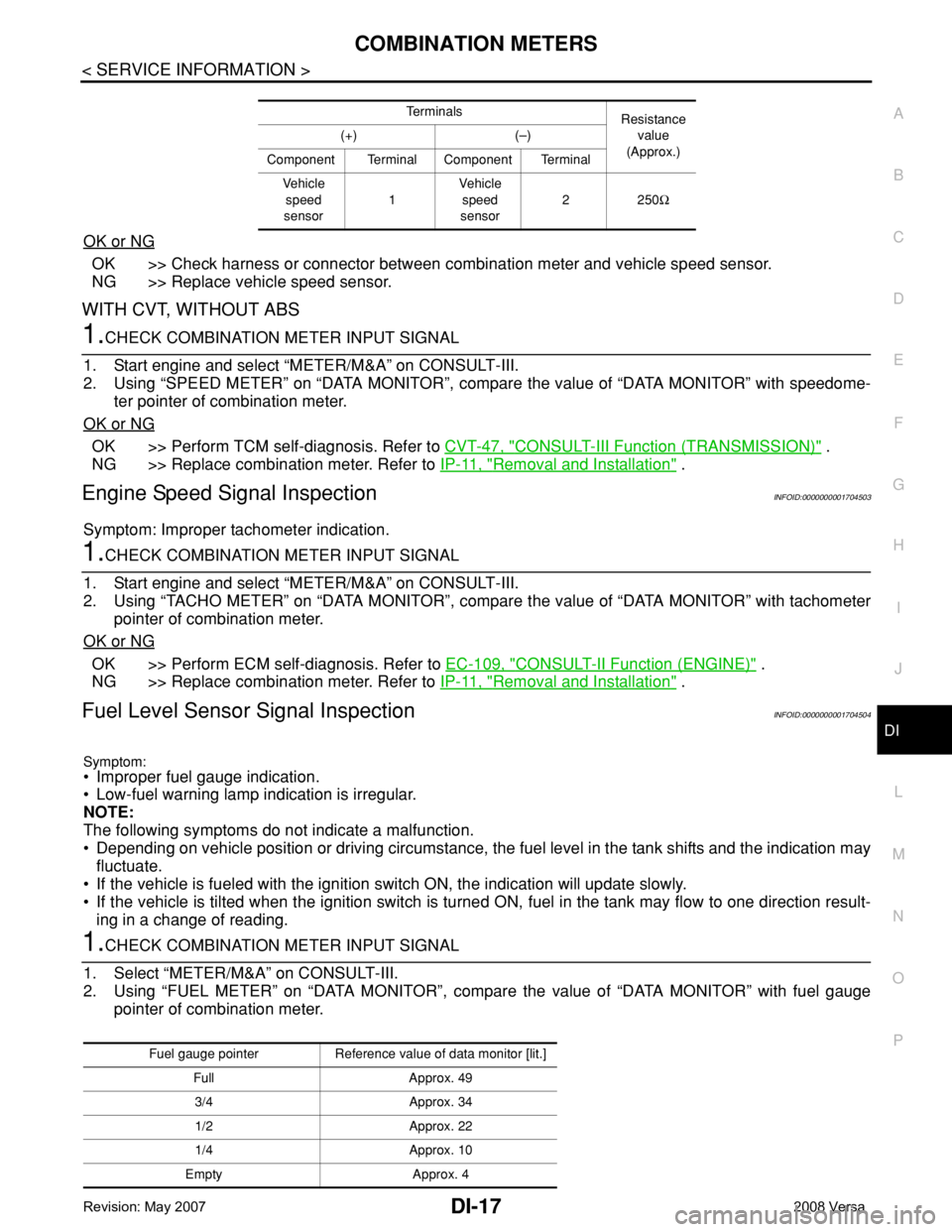
1.CHECK COMBINATION METER INPUT SIGNAL
1. Select “METER/M&A” on CONSULT-III.
2. Using “FUEL METER” on “DATA MONITOR”, compare the value of “DATA MONITOR” with fuel gauge
pointer of combination meter.
Te r m i n a l s
Resistance
value
(Approx.) (+) (–)
Component Terminal Component Terminal
Ve h i c l e
speed
sensor1Vehicle
speed
sensor2250Ω
Fuel gauge pointer Reference value of data monitor [lit.]
Full Approx. 49
3/4 Approx. 34
1/2 Approx. 22
1/4 Approx. 10
Empty Approx. 4
Page 1039 of 2771
DI-18
< SERVICE INFORMATION >
COMBINATION METERS
OK or NG
OK >> GO TO 2.
NG >> Replace combination meter. Refer to IP-11, "
Removal and Installation" .
2.CHECK HARNESS CONNECTOR
1. Turn ignition switch OFF.
2. Check combination meter and fuel level sensor unit terminals (meter-side and harness-side) for poor con-
nection.
OK or NG
OK >> GO TO 3.
NG >> Repair or replace terminals or connectors.
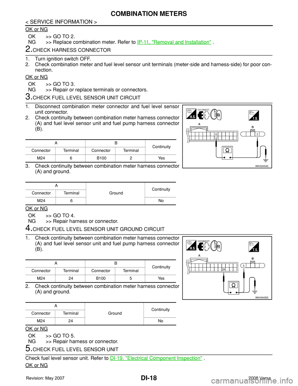
3.CHECK FUEL LEVEL SENSOR UNIT CIRCUIT
1. Disconnect combination meter connector and fuel level sensor
unit connector.
2. Check continuity between combination meter harness connector
(A) and fuel level sensor unit and fuel pump harness connector
(B).
3. Check continuity between combination meter harness connector
(A) and ground.
OK or NG
OK >> GO TO 4.
NG >> Repair harness or connector.
4.CHECK FUEL LEVEL SENSOR UNIT GROUND CIRCUIT
1. Check continuity between combination meter harness connector
(A) and fuel level sensor unit and fuel pump harness connector
(B).
2. Check continuity between combination meter harness connector
(A) and ground.
OK or NG
OK >> GO TO 5.
NG >> Repair harness or connector.
5.CHECK FUEL LEVEL SENSOR UNIT
Check fuel level sensor unit. Refer to DI-19, "
Electrical Component Inspection" .
OK or NG
AB
Continuity
Connector Terminal Connector Terminal
M24 6 B100 2 Yes
A
GroundContinuity
Connector Terminal
M24 6 No
WKIA5454E
AB
Continuity
Connector Terminal Connector Terminal
M24 24 B100 5 Yes
A
GroundContinuity
Connector Terminal
M24 24 No
WKIA5455E
Page 1040 of 2771
COMBINATION METERS
DI-19
< SERVICE INFORMATION >
C
D
E
F
G
H
I
J
L
MA
B
DI
N
O
P
OK >> Check fuel level sensor unit installation, and check whether the float arm interferes or binds with
any of the internal components in the fuel tank. Repair or replace malfunctioning part, if neces-
sary.
NG >> Replace fuel level sensor unit.
Fuel Gauge Fluctuates, Indicates Wrong Value, or VariesINFOID:0000000001704505
1.CHECK FUEL GAUGE FLUCTUATION
Test drive vehicle to see if gauge fluctuates only during driving or at the instant of stopping.
Does the indication value vary only during driving or at the at the instant of stopping?
YES >> The pointer fluctuation may be caused by fuel level change in the fuel tank. Condition is normal.
NO >> Ask the customer about the situation when the symptom occurs in detail, and perform the trouble
diagnosis.
Fuel Gauge Does Not Move to Full-positionINFOID:0000000001704506
1.OBSERVE FUEL GAUGE
Does it take a long time for the pointer to move to FULL position?
YES or NO
YES >> GO TO 2.
NO >> GO TO 3.
2.IDENTIFY FUELING CONDITION
Was the vehicle fueled with the ignition switch ON?
YES or NO
YES >> Be sure to fuel the vehicle with the ignition switch OFF. Otherwise, it will take a long time to move
to FULL position because of the characteristic of the fuel gauge.
NO >> GO TO 3.
3.OBSERVE VEHICLE POSITION
Is the vehicle parked on an incline?
YES or NO
YES >> Check the fuel level indication with vehicle on a level surface.
NO >> GO TO 4.
4.OBSERVE FUEL GAUGE POINTER
During driving, does the fuel gauge pointer move gradually toward EMPTY position?
YES or NO
YES >> Check the components. Refer to DI-19, "Electrical Component Inspection" .
NO >> The float arm may interfere or bind with any of the components in the fuel tank.
DTC [U1000] CAN Communication CircuitINFOID:0000000001704507
Symptom: Display CAN COMM CIRC [U1000] at the result of self-diagnosis for combination meter.
1.CHECK CAN COMMUNICATION
1. Select "SELF-DIAG RESULTS" mode for "METER/M&A" with CONSULT-III.
2. Print out CONSULT-III screen.
>> Go to "CAN SYSTEM". Refer to LAN-15, "
Trouble Diagnosis Flow Chart".
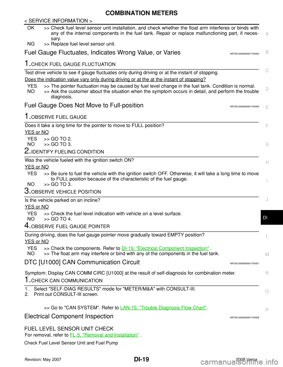
Electrical Component InspectionINFOID:0000000001704508
FUEL LEVEL SENSOR UNIT CHECK
For removal, refer to FL-5, "Removal and Installation" .
Check Fuel Level Sensor Unit and Fuel Pump
Page 1041 of 2771
DI-20
< SERVICE INFORMATION >
COMBINATION METERS
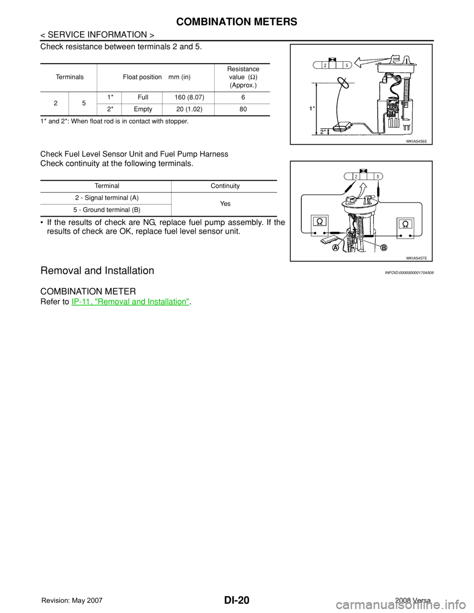
Check resistance between terminals 2 and 5.
1* and 2*: When float rod is in contact with stopper.
Check Fuel Level Sensor Unit and Fuel Pump Harness
Check continuity at the following terminals.
• If the results of check are NG, replace fuel pump assembly. If the
results of check are OK, replace fuel level sensor unit.
Removal and InstallationINFOID:0000000001704509
COMBINATION METER
Refer to IP-11, "Removal and Installation".
Terminals Float position mm (in)Resistance
value (Ω)
(Approx.)
251* Full 160 (8.07) 6
2* Empty 20 (1.02) 80
WKIA5456E
Terminal Continuity
2 - Signal terminal (A)
Ye s
5 - Ground terminal (B)
WKIA5457E
Page 1075 of 2771

EC-1
ENGINE
C
D
E
F
G
H
I
J
K
L
M
SECTION EC
A
EC
N
O
P
CONTENTS
ENGINE CONTROL SYSTEM
SERVICE INFORMATION ............................9
INDEX FOR DTC .................................................9
DTC No. Index ..........................................................9
Alphabetical Index ...................................................12
PRECAUTIONS ..................................................16
Precaution for Supplemental Restraint System
(SRS) "AIR BAG" and "SEAT BELT PRE-TEN-
SIONER" .................................................................
16
Precaution for Procedure without Cowl Top Cover ....16
On Board Diagnosis (OBD) System of Engine and
A/T, CVT .................................................................
16
Precaution ...............................................................17
PREPARATION ..................................................20
Special Service Tool ...............................................20
Commercial Service Tool ........................................21
ENGINE CONTROL SYSTEM ............................22
Schematic ...............................................................22
Multiport Fuel Injection (MFI) System .....................22
Electronic Ignition (EI) System ................................25
Fuel Cut Control (at No Load and High Engine
Speed) .....................................................................
25
AIR CONDITIONING CUT CONTROL ...............27
Input/Output Signal Chart ........................................27
System Description .................................................27
AUTOMATIC SPEED CONTROL DEVICE
(ASCD) ...............................................................
28
System Description .................................................28
Component Description ...........................................29
CAN COMMUNICATION ....................................30
System Description .................................................30
EVAPORATIVE EMISSION SYSTEM ................31
Description ..............................................................31
Component Inspection ............................................33
Removal and Installation .........................................35
How to Detect Fuel Vapor Leakage .........................35
ON BOARD REFUELING VAPOR RECOV-
ERY (ORVR) ......................................................
38
System Description ..................................................38
Diagnosis Procedure ...............................................38
Component Inspection .............................................40
POSITIVE CRANKCASE VENTILATION .........43
Description ...............................................................43
Component Inspection .............................................43
NVIS (NISSAN VEHICLE IMMOBILIZER SYS-
TEM-NATS) .......................................................
45
Description ...............................................................45
ON BOARD DIAGNOSTIC (OBD) SYSTEM ....46
Introduction ..............................................................46
Two Trip Detection Logic .........................................46
Emission-related Diagnostic Information .................47
Malfunction Indicator Lamp (MIL) ............................60
OBD System Operation Chart .................................63
BASIC SERVICE PROCEDURE .......................69
Basic Inspection ......................................................69
Idle Speed and Ignition Timing Check .....................73
Procedure After Replacing ECM .............................75
VIN Registration ......................................................75
Accelerator Pedal Released Position Learning .......76
Throttle Valve Closed Position Learning .................76
Idle Air Volume Learning .........................................76
Fuel Pressure Check ...............................................78
TROUBLE DIAGNOSIS ....................................81
Trouble Diagnosis Introduction ................................81
DTC Inspection Priority Chart ..................................86
Fail-Safe Chart ........................................................87
Symptom Matrix Chart .............................................88
Engine Control Component Parts Location .............93
Vacuum Hose Drawing ............................................99
Circuit Diagram ......................................................100
ECM Harness Connector Terminal Layout ............102
Page 1077 of 2771

EC-3
C
D
E
F
G
H
I
J
K
L
M
ECA
N
O
P Diagnosis Procedure .............................................
189
Component Inspection ..........................................191
Removal and Installation .......................................191
DTC P0122, P0123 TP SENSOR .....................192
Component Description .........................................192
CONSULT-II Reference Value in Data Monitor
Mode .....................................................................
192
On Board Diagnosis Logic ....................................192
DTC Confirmation Procedure ................................192
Wiring Diagram .....................................................194
Diagnosis Procedure .............................................195
Component Inspection ..........................................197
Removal and Installation .......................................197
DTC P0125 ECT SENSOR ...............................198
Description ............................................................198
On Board Diagnosis Logic ....................................198
DTC Confirmation Procedure ................................198
Diagnosis Procedure .............................................199
Component Inspection ..........................................200
Removal and Installation .......................................200
DTC P0127 IAT SENSOR ................................201
Component Description .........................................201
On Board Diagnosis Logic ....................................201
DTC Confirmation Procedure ................................201
Diagnosis Procedure .............................................202
Component Inspection ..........................................202
Removal and Installation .......................................203
DTC P0128 THERMOSTAT FUNCTION ..........204
On Board Diagnosis Logic ....................................204
DTC Confirmation Procedure ................................204
Diagnosis Procedure .............................................204
Component Inspection ..........................................204
Removal and Installation .......................................205
DTC P0130 A/F SENSOR 1 .............................206
Component Description .........................................206
CONSULT-II Reference Value in Data Monitor
Mode .....................................................................
206
On Board Diagnosis Logic ....................................206
DTC Confirmation Procedure ................................206
Overall Function Check .........................................208
Wiring Diagram .....................................................209
Diagnosis Procedure .............................................210
Removal and Installation .......................................212
DTC P0131 A/F SENSOR 1 .............................213
Component Description .........................................213
CONSULT-II Reference Value in Data Monitor
Mode .....................................................................
213
On Board Diagnosis Logic ....................................213
DTC Confirmation Procedure ................................213
Wiring Diagram .....................................................215
Diagnosis Procedure .............................................216
Removal and Installation .......................................218
DTC P0132 A/F SENSOR 1 .............................219
Component Description .........................................219
CONSULT-II Reference Value in Data Monitor
Mode ......................................................................
219
On Board Diagnosis Logic .....................................219
DTC Confirmation Procedure ................................219
Wiring Diagram ......................................................221
Diagnosis Procedure .............................................222
Removal and Installation .......................................224
DTC P0133 A/F SENSOR 1 ............................225
Component Description .........................................225
CONSULT-II Reference Value in Data Monitor
Mode ......................................................................
225
On Board Diagnosis Logic .....................................225
DTC Confirmation Procedure ................................225
Wiring Diagram ......................................................228
Diagnosis Procedure .............................................229
Removal and Installation .......................................232
DTC P0137 HO2S2 .........................................233
Component Description .........................................233
CONSULT-II Reference Value in Data Monitor
Mode ......................................................................
233
On Board Diagnosis Logic .....................................233
DTC Confirmation Procedure ................................233
Overall Function Check .........................................234
Wiring Diagram ......................................................235
Diagnosis Procedure .............................................236
Component Inspection ...........................................238
Removal and Installation .......................................239
DTC P0138 HO2S2 .........................................240
Component Description .........................................240
CONSULT-II Reference Value in Data Monitor
Mode ......................................................................
240
On Board Diagnosis Logic .....................................240
DTC Confirmation Procedure ................................241
Overall Function Check .........................................242
Wiring Diagram ......................................................243
Diagnosis Procedure .............................................244
Component Inspection ...........................................247
Removal and Installation .......................................248
DTC P0139 HO2S2 .........................................250
Component Description .........................................250
CONSULT-II Reference Value in Data Monitor
Mode ......................................................................
250
On Board Diagnosis Logic .....................................250
DTC Confirmation Procedure ................................250
Overall Function Check .........................................251
Wiring Diagram ......................................................252
Diagnosis Procedure .............................................253
Component Inspection ...........................................255
Removal and Installation .......................................256
DTC P0171 FUEL INJECTION SYSTEM
FUNCTION ......................................................
257
On Board Diagnosis Logic .....................................257
DTC Confirmation Procedure ................................257
Wiring Diagram ......................................................259
Page 1078 of 2771

EC-4
Diagnosis Procedure .............................................260
DTC P0172 FUEL INJECTION SYSTEM
FUNCTION .......................................................
264
On Board Diagnosis Logic .....................................264
DTC Confirmation Procedure ................................264
Wiring Diagram ......................................................266
Diagnosis Procedure .............................................267
DTC P0181 FTT SENSOR ...............................270
Component Description .........................................270
On Board Diagnosis Logic .....................................270
DTC Confirmation Procedure ................................270
Wiring Diagram ......................................................271
Diagnosis Procedure .............................................271
Component Inspection ...........................................273
Removal and Installation .......................................273
DTC P0182, P0183 FTT SENSOR ..................274
Component Description .........................................274
On Board Diagnosis Logic .....................................274
DTC Confirmation Procedure ................................274
Wiring Diagram ......................................................275
Diagnosis Procedure .............................................275
Component Inspection ...........................................277
Removal and Installation .......................................277
DTC P0222, P0223 TP SENSOR ....................278
Component Description .........................................278
CONSULT-II Reference Value in Data Monitor
Mode ......................................................................
278
On Board Diagnosis Logic .....................................278
DTC Confirmation Procedure ................................278
Wiring Diagram ......................................................280
Diagnosis Procedure .............................................281
Component Inspection ...........................................283
Removal and Installation .......................................283
DTC P0300 - P0304 MULTIPLE CYLINDER
MISFIRE, NO. 1 - 4 CYLINDER MISFIRE .......
284
On Board Diagnosis Logic .....................................284
DTC Confirmation Procedure ................................284
Diagnosis Procedure .............................................285
DTC P0327, P0328 KS ....................................291
Component Description .........................................291
On Board Diagnosis Logic .....................................291
DTC Confirmation Procedure ................................291
Wiring Diagram ......................................................292
Diagnosis Procedure .............................................293
Component Inspection ...........................................294
Removal and Installation .......................................294
DTC P0335 CKP SENSOR (POS) ...................295
Component Description .........................................295
CONSULT-II Reference Value in Data Monitor
Mode ......................................................................
295
On Board Diagnosis Logic .....................................295
DTC Confirmation Procedure ................................295
Wiring Diagram ......................................................297
Diagnosis Procedure .............................................298
Component Inspection ..........................................301
Removal and Installation .......................................301
DTC P0340 CMP SENSOR (PHASE) ..............302
Component Description ........................................302
CONSULT-II Reference Value in Data Monitor
Mode .....................................................................
302
On Board Diagnosis Logic ....................................302
DTC Confirmation Procedure ................................302
Wiring Diagram .....................................................304
Diagnosis Procedure .............................................305
Component Inspection ..........................................307
Removal and Installation .......................................307
DTC P0420 THREE WAY CATALYST FUNC-
TION ..................................................................
308
On Board Diagnosis Logic ....................................308
DTC Confirmation Procedure ................................308
Overall Function Check .........................................309
Diagnosis Procedure .............................................310
DTC P0441 EVAP CONTROL SYSTEM ..........313
System Description ...............................................313
On Board Diagnosis Logic ....................................313
DTC Confirmation Procedure ................................313
Overall Function Check .........................................314
Diagnosis Procedure .............................................315
DTC P0442 EVAP CONTROL SYSTEM ..........318
On Board Diagnosis Logic ....................................318
DTC Confirmation Procedure ................................318
Diagnosis Procedure .............................................320
DTC P0443 EVAP CANISTER PURGE VOL-
UME CONTROL SOLENOID VALVE ...............
325
Description ............................................................325
CONSULT-II Reference Value in Data Monitor
Mode .....................................................................
325
On Board Diagnosis Logic ....................................326
DTC Confirmation Procedure ................................326
Wiring Diagram .....................................................327
Diagnosis Procedure .............................................328
Component Inspection ..........................................331
Removal and Installation .......................................331
DTC P0444, P0445 EVAP CANISTER PURGE
VOLUME CONTROL SOLENOID VALVE .......
332
Description ............................................................332
CONSULT-II Reference Value in Data Monitor
Mode .....................................................................
332
On Board Diagnosis Logic ....................................333
DTC Confirmation Procedure ................................333
Wiring Diagram .....................................................334
Diagnosis Procedure .............................................335
Component Inspection ..........................................337
Removal and Installation .......................................337
DTC P0447 EVAP CANISTER VENT CON-
TROL VALVE ...................................................
338
Page 1079 of 2771

EC-5
C
D
E
F
G
H
I
J
K
L
M
ECA
N
O
P Component Description .........................................
338
CONSULT-II Reference Value in Data Monitor
Mode .....................................................................
338
On Board Diagnosis Logic ....................................338
DTC Confirmation Procedure ................................338
Wiring Diagram .....................................................340
Diagnosis Procedure .............................................341
Component Inspection ..........................................343
DTC P0448 EVAP CANISTER VENT CON-
TROL VALVE ...................................................
345
Component Description .........................................345
CONSULT-II Reference Value in Data Monitor
Mode .....................................................................
345
On Board Diagnosis Logic ....................................345
DTC Confirmation Procedure ................................345
Wiring Diagram .....................................................347
Diagnosis Procedure .............................................348
Component Inspection ..........................................349
DTC P0451 EVAP CONTROL SYSTEM
PRESSURE SENSOR ......................................
351
Component Description .........................................351
CONSULT-II Reference Value in Data Monitor
Mode .....................................................................
351
On Board Diagnosis Logic ....................................351
DTC Confirmation Procedure ................................351
Diagnosis Procedure .............................................352
Component Inspection ..........................................353
DTC P0452 EVAP CONTROL SYSTEM
PRESSURE SENSOR ......................................
355
Component Description .........................................355
CONSULT-II Reference Value in Data Monitor
Mode .....................................................................
355
On Board Diagnosis Logic ....................................355
DTC Confirmation Procedure ................................355
Wiring Diagram .....................................................357
Diagnosis Procedure .............................................358
Component Inspection ..........................................361
DTC P0453 EVAP CONTROL SYSTEM
PRESSURE SENSOR ......................................
362
Component Description .........................................362
CONSULT-II Reference Value in Data Monitor
Mode .....................................................................
362
On Board Diagnosis Logic ....................................362
DTC Confirmation Procedure ................................362
Wiring Diagram .....................................................364
Diagnosis Procedure .............................................365
Component Inspection ..........................................369
DTC P0455 EVAP CONTROL SYSTEM ..........370
On Board Diagnosis Logic ....................................370
DTC Confirmation Procedure ................................370
Diagnosis Procedure .............................................372
DTC P0456 EVAP CONTROL SYSTEM ..........377
On Board Diagnosis Logic ....................................377
DTC Confirmation Procedure ................................378
Overall Function Check .........................................378
Diagnosis Procedure .............................................379
DTC P0460 FUEL LEVEL SENSOR ...............385
Component Description .........................................385
On Board Diagnosis Logic .....................................385
DTC Confirmation Procedure ................................385
Diagnosis Procedure .............................................386
Removal and Installation .......................................386
DTC P0461 FUEL LEVEL SENSOR ...............387
Component Description .........................................387
On Board Diagnosis Logic .....................................387
Overall Function Check .........................................387
Diagnosis Procedure .............................................388
Removal and Installation .......................................388
DTC P0462, P0463 FUEL LEVEL SENSOR ..389
Component Description .........................................389
On Board Diagnosis Logic .....................................389
DTC Confirmation Procedure ................................389
Diagnosis Procedure .............................................390
Removal and Installation .......................................390
DTC P0500 VSS ..............................................391
Description .............................................................391
On Board Diagnosis Logic .....................................391
DTC Confirmation Procedure ................................391
Overall Function Check .........................................392
Diagnosis Procedure .............................................392
DTC P0506 ISC SYSTEM ...............................393
Description .............................................................393
On Board Diagnosis Logic .....................................393
DTC Confirmation Procedure ................................393
Diagnosis Procedure .............................................393
DTC P0507 ISC SYSTEM ...............................395
Description .............................................................395
On Board Diagnosis Logic .....................................395
DTC Confirmation Procedure ................................395
Diagnosis Procedure .............................................395
DTC P0605 ECM .............................................397
Component Description .........................................397
On Board Diagnosis Logic .....................................397
DTC Confirmation Procedure ................................397
Diagnosis Procedure .............................................398
DTC P0643 SENSOR POWER SUPPLY ........400
On Board Diagnosis Logic .....................................400
DTC Confirmation Procedure ................................400
Wiring Diagram ......................................................401
Diagnosis Procedure .............................................402
DTC P0850 PNP SWITCH ..............................405
Component Description .........................................405
CONSULT-II Reference Value in Data Monitor
Mode ......................................................................
405
On Board Diagnosis Logic .....................................405
DTC Confirmation Procedure ................................405
Page 1081 of 2771

EC-7
C
D
E
F
G
H
I
J
K
L
M
ECA
N
O
P
DTC P2119 ELECTRIC THROTTLE CON-
TROL ACTUATOR ...........................................
472
Component Description .........................................472
On Board Diagnosis Logic ....................................472
DTC Confirmation Procedure ................................472
Diagnosis Procedure .............................................473
DTC P2122, P2123 APP SENSOR ..................474
Component Description .........................................474
CONSULT-II Reference Value in Data Monitor
Mode .....................................................................
474
On Board Diagnosis Logic ....................................474
DTC Confirmation Procedure ................................474
Wiring Diagram .....................................................476
Diagnosis Procedure .............................................477
Component Inspection ..........................................479
Removal and Installation .......................................479
DTC P2127, P2128 APP SENSOR ..................480
Component Description .........................................480
CONSULT-II Reference Value in Data Monitor
Mode .....................................................................
480
On Board Diagnosis Logic ....................................480
DTC Confirmation Procedure ................................481
Wiring Diagram .....................................................482
Diagnosis Procedure .............................................483
Component Inspection ..........................................485
Removal and Installation .......................................486
DTC P2135 TP SENSOR .................................487
Component Description .........................................487
CONSULT-II Reference Value in Data Monitor
Mode .....................................................................
487
On Board Diagnosis Logic ....................................487
DTC Confirmation Procedure ................................487
Wiring Diagram .....................................................489
Diagnosis Procedure .............................................490
Component Inspection ..........................................492
Removal and Installation .......................................492
DTC P2138 APP SENSOR ...............................493
Component Description .........................................493
CONSULT-II Reference Value in Data Monitor
Mode .....................................................................
493
On Board Diagnosis Logic ....................................493
DTC Confirmation Procedure ................................494
Wiring Diagram .....................................................495
Diagnosis Procedure .............................................496
Component Inspection ..........................................499
Removal and Installation .......................................499
DTC P2A00 A/F SENSOR 1 .............................500
Component Description .........................................500
CONSULT-II Reference Value in Data Monitor
Mode .....................................................................
500
On Board Diagnosis Logic ....................................500
DTC Confirmation Procedure ................................500
Wiring Diagram .....................................................502
Diagnosis Procedure .............................................503
Removal and Installation .......................................507
ASCD BRAKE SWITCH ..................................508
Component Description .........................................508
CONSULT-II Reference Value in Data Monitor
Mode ......................................................................
508
Wiring Diagram ......................................................509
Diagnosis Procedure .............................................510
Component Inspection ...........................................514
ASCD INDICATOR ..........................................516
Component Description .........................................516
CONSULT-II Reference Value in Data Monitor
Mode ......................................................................
516
Wiring Diagram ......................................................517
Diagnosis Procedure .............................................517
ELECTRICAL LOAD SIGNAL ........................519
CONSULT-II Reference Value in Data Monitor
Mode ......................................................................
519
Diagnosis Procedure .............................................519
FUEL INJECTOR ............................................521
Component Description .........................................521
CONSULT-II Reference Value in Data Monitor
Mode ......................................................................
521
Wiring Diagram ......................................................522
Diagnosis Procedure .............................................523
Component Inspection ...........................................525
Removal and Installation .......................................525
FUEL PUMP ....................................................526
Description .............................................................526
CONSULT-II Reference Value in Data Monitor
Mode ......................................................................
526
Wiring Diagram ......................................................527
Diagnosis Procedure .............................................528
Component Inspection ...........................................530
Removal and Installation .......................................530
IGNITION SIGNAL ..........................................531
Component Description .........................................531
Wiring Diagram ......................................................532
Diagnosis Procedure .............................................535
Component Inspection ...........................................538
Removal and Installation .......................................540
REFRIGERANT PRESSURE SENSOR ..........541
Component Description .........................................541
Wiring Diagram ......................................................542
Diagnosis Procedure .............................................543
Removal and Installation .......................................545
MIL AND DATA LINK CONNECTOR .............546
Wiring Diagram ......................................................546
SERVICE DATA AND SPECIFICATIONS
(SDS) ...............................................................
548
Fuel Pressure ........................................................548
Idle Speed and Ignition Timing ..............................548
Calculated Load Value ..........................................548
Mass Air Flow Sensor ............................................548
Intake Air Temperature Sensor .............................548
Page 1082 of 2771

EC-8
Engine Coolant Temperature Sensor ....................548
Air Fuel Ratio (A/F) Sensor 1 Heater .....................549
Heated Oxygen sensor 2 Heater ...........................549
Crankshaft Position Sensor (POS) ........................549
Camshaft Position Sensor (PHASE) .....................549
Throttle Control Motor ...........................................549
Fuel Injector ..........................................................549
Fuel Pump .............................................................549