fuel NISSAN TIIDA 2008 Service Owner's Guide
[x] Cancel search | Manufacturer: NISSAN, Model Year: 2008, Model line: TIIDA, Model: NISSAN TIIDA 2008Pages: 2771, PDF Size: 60.61 MB
Page 1083 of 2771
INDEX FOR DTC
EC-9
< SERVICE INFORMATION >
C
D
E
F
G
H
I
J
K
L
MA
EC
N
P O
SERVICE INFORMATION
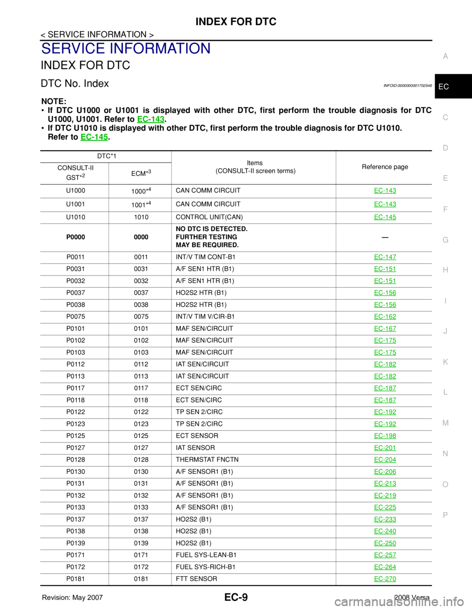
INDEX FOR DTC
DTC No. IndexINFOID:0000000001702546
NOTE:
•If DTC U1000 or U1001 is displayed with other DTC, first perform the trouble diagnosis for DTC
U1000, U1001. Refer to EC-143
.
•If DTC U1010 is displayed with other DTC, first perform the trouble diagnosis for DTC U1010.
Refer to EC-145
.
DTC*1
Items
(CONSULT-II screen terms)Reference page
CONSULT-II
GST*
2ECM*3
U1000
1000*4CAN COMM CIRCUITEC-143
U1001
1001*4CAN COMM CIRCUITEC-143
U1010 1010 CONTROL UNIT(CAN)EC-145
P0000 0000NO DTC IS DETECTED.
FURTHER TESTING
MAY BE REQUIRED.—
P0011 0011 INT/V TIM CONT-B1EC-147
P0031 0031 A/F SEN1 HTR (B1)EC-151
P0032 0032 A/F SEN1 HTR (B1)EC-151
P0037 0037 HO2S2 HTR (B1)EC-156
P0038 0038 HO2S2 HTR (B1)EC-156
P0075 0075 INT/V TIM V/CIR-B1EC-162
P0101 0101 MAF SEN/CIRCUITEC-167
P0102 0102 MAF SEN/CIRCUITEC-175
P0103 0103 MAF SEN/CIRCUITEC-175
P0112 0112 IAT SEN/CIRCUITEC-182
P0113 0113 IAT SEN/CIRCUITEC-182
P0117 0117 ECT SEN/CIRCEC-187
P0118 0118 ECT SEN/CIRCEC-187
P0122 0122 TP SEN 2/CIRCEC-192
P0123 0123 TP SEN 2/CIRCEC-192
P0125 0125 ECT SENSOREC-198
P0127 0127 IAT SENSOREC-201
P0128 0128 THERMSTAT FNCTNEC-204
P0130 0130 A/F SENSOR1 (B1)EC-206
P0131 0131 A/F SENSOR1 (B1)EC-213
P0132 0132 A/F SENSOR1 (B1)EC-219
P0133 0133 A/F SENSOR1 (B1)EC-225
P0137 0137 HO2S2 (B1)EC-233
P0138 0138 HO2S2 (B1)EC-240
P0139 0139 HO2S2 (B1)EC-250
P0171 0171 FUEL SYS-LEAN-B1EC-257
P0172 0172 FUEL SYS-RICH-B1EC-264
P0181 0181 FTT SENSOREC-270
Page 1084 of 2771

EC-10
< SERVICE INFORMATION >
INDEX FOR DTC
P0182 0182 FTT SEN/CIRCUITEC-274
P0183 0183 FTT SEN/CIRCUITEC-274
P0222 0222 TP SEN 1/CIRCEC-278
P0223 0223 TP SEN 1/CIRCEC-278
P0300 0300 MULTI CYL MISFIREEC-284
P0301 0301 CYL 1 MISFIREEC-284
P0302 0302 CYL 2 MISFIREEC-284
P0303 0303 CYL 3 MISFIREEC-284
P0304 0304 CYL 4 MISFIREEC-284
P0327 0327 KNOCK SEN/CIRC-B1EC-291
P0328 0328 KNOCK SEN/CIRC-B1EC-291
P0335 0335 CKP SEN/CIRCUITEC-295
P0340 0340 CMP SEN/CIRC-B1EC-302
P0420 0420 TW CATALYST SYS-B1EC-308
P0441 0441 EVAP PURG FLOW/MONEC-313
P0442 0442 EVAP SMALL LEAKEC-318
P0443 0443 PURG VOLUME CONT/VEC-325
P0444 0444 PURG VOLUME CONT/VEC-332
P0445 0445 PURG VOLUME CONT/VEC-332
P0447 0447 VENT CONTROL VALVEEC-338
P0448 0448 VENT CONTROL VALVEEC-345
P0451 0451 EVAP SYS PRES SENEC-351
P0452 0452 EVAP SYS PRES SENEC-355
P0453 0453 EVAP SYS PRES SENEC-362
P0455 0455 EVAP GROSS LEAKEC-370
P0456 0456 EVAP VERY SML LEAKEC-377
P0460 0460 FUEL LEV SEN SLOSHEC-385
P0461 0461 FUEL LEVEL SENSOREC-387
P0462 0462 FUEL LEVL SEN/CIRCEC-389
P0463 0463 FUEL LEVL SEN/CIRCEC-389
P0500 0500
VEH SPEED SEN/CIRC*5EC-391
P0506 0506 ISC SYSTEMEC-393
P0507 0507 ISC SYSTEMEC-395
P0605 0605 ECMEC-397
P0643 0643 SENSOR POWER/CIRCEC-400
P0705 0705 PNP SW/CIRCAT- 8 6 (A/T),
CVT-65
(CVT)
P0710 0710 ATF TEMP SEN/CIRCAT- 9 1
(A/T),
CVT-71
(CVT)
P0715 0715 INPUT SPD SEN/CIRCCVT-76
P0720 0720
VEH SPD SEN/CIR AT*5AT- 9 6 (A/T),
CVT-80
(CVT)
P0725 0725 ENGINE SPEED SIGAT- 1 0 1
DTC*1
Items
(CONSULT-II screen terms)Reference page
CONSULT-II
GST*
2ECM*3
Page 1087 of 2771
INDEX FOR DTC
EC-13
< SERVICE INFORMATION >
C
D
E
F
G
H
I
J
K
L
MA
EC
N
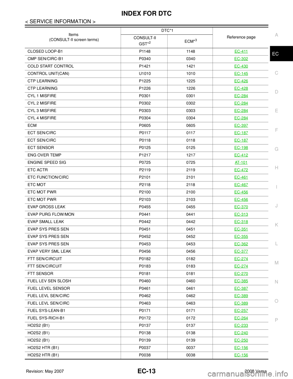
P OC L O S E D L O O P - B 1 P 11 4 8 11 4 8EC-411
CMP SEN/CIRC-B1 P0340 0340EC-302
COLD START CONTROL P1421 1421EC-430
CONTROL UNIT(CAN) U1010 1010EC-145
CTP LEARNING P1225 1225EC-426
CTP LEARNING P1226 1226EC-428
CYL 1 MISFIRE P0301 0301EC-284
CYL 2 MISFIRE P0302 0302EC-284
CYL 3 MISFIRE P0303 0303EC-284
CYL 4 MISFIRE P0304 0304EC-284
ECM P0605 0605EC-397
ECT SEN/CIRC P0117 0117EC-187
ECT SEN/CIRC P0118 0118EC-187
ECT SENSOR P0125 0125 EC-198
ENG OVER TEMP P1217 1217EC-412
ENGINE SPEED SIG P0725 0725AT- 1 0 1
ETC ACTR P2119 2119EC-472
ETC FUNCTION/CIRC P2101 2101EC-461
ETC MOT P2118 2118EC-467
ETC MOT PWR P2100 2100EC-456
ETC MOT PWR P2103 2103EC-456
EVAP GROSS LEAK P0455 0455EC-370
EVAP PURG FLOW/MON P0441 0441EC-313
EVAP SMALL LEAK P0442 0442EC-318
EVAP SYS PRES SEN P0451 0451EC-351
EVAP SYS PRES SEN P0452 0452EC-355
EVAP SYS PRES SEN P0453 0453EC-362
EVAP VERY SML LEAK P0456 0456EC-377
FTT SEN/CIRCUIT P0182 0182EC-274
FTT SEN/CIRCUIT P0183 0183EC-274
FTT SENSOR P0181 0181EC-270
FUEL LEV SEN SLOSH P0460 0460EC-385
FUEL LEVEL SENSOR P0461 0461EC-387
FUEL LEVL SEN/CIRC P0462 0462EC-389
FUEL LEVL SEN/CIRC P0463 0463EC-389
FUEL SYS-LEAN-B1 P0171 0171EC-257
FUEL SYS-RICH-B1 P0172 0172EC-264
HO2S2 (B1) P0137 0137EC-233
HO2S2 (B1) P0138 0138EC-240
HO2S2 (B1) P0139 0139EC-250
HO2S2 HTR (B1) P0037 0037EC-156
HO2S2 HTR (B1) P0038 0038EC-156
Items
(CONSULT-II screen terms)DTC*1
Reference page
CONSULT-II
GST*
2ECM*3
Page 1090 of 2771

EC-16
< SERVICE INFORMATION >
PRECAUTIONS
PRECAUTIONS
Precaution for Supplemental Restraint System (SRS) "AIR BAG" and "SEAT BELT
PRE-TENSIONER"
INFOID:0000000001702548
The Supplemental Restraint System such as “AIR BAG” and “SEAT BELT PRE-TENSIONER”, used along
with a front seat belt, helps to reduce the risk or severity of injury to the driver and front passenger for certain
types of collision. This system includes seat belt switch inputs and dual stage front air bag modules. The SRS
system uses the seat belt switches to determine the front air bag deployment, and may only deploy one front
air bag, depending on the severity of a collision and whether the front occupants are belted or unbelted.
Information necessary to service the system safely is included in the SRS and SB section of this Service Man-
ual.
WARNING:
• To avoid rendering the SRS inoperative, which could increase the risk of personal injury or death in
the event of a collision which would result in air bag inflation, all maintenance must be performed by
an authorized NISSAN/INFINITI dealer.
• Improper maintenance, including incorrect removal and installation of the SRS, can lead to personal
injury caused by unintentional activation of the system. For removal of Spiral Cable and Air Bag
Module, see the SRS section.
• Do not use electrical test equipment on any circuit related to the SRS unless instructed to in this
Service Manual. SRS wiring harnesses can be identified by yellow and/or orange harnesses or har-
ness connectors.
Precaution for Procedure without Cowl Top CoverINFOID:0000000001702549
When performing the procedure after removing cowl top cover, cover
the lower end of windshield with urethane, etc.
On Board Diagnosis (OBD) System of Engine and A/T, CVTINFOID:0000000001702550
The ECM has an on board diagnostic system. It will light up the malfunction indicator lamp (MIL) to warn the
driver of a malfunction causing emission deterioration.
CAUTION:
• Be sure to turn the ignition switch OFF and disconnect the battery ground cable before any repair or
inspection work. The open/short circuit of related switches, sensors, solenoid valves, etc. will cause
the MIL to light up.
• Be sure to connect and lock the connectors securely after work. A loose (unlocked) connector will
cause the MIL to light up due to the open circuit. (Be sure the connector is free from water, grease,
dirt, bent terminals, etc.)
• Certain systems and components, especially those related to OBD, may use a new style slide-lock-
ing type harness connector. For description and how to disconnect, refer to PG-65
.
• Be sure to route and secure the harnesses properly after work. The interference of the harness with
a bracket, etc. may cause the MIL to light up due to the short circuit.
• Be sure to connect rubber tubes properly after work. A misconnected or disconnected rubber tube
may cause the MIL to light up due to the malfunction of the fuel injection system, etc.
• Be sure to erase the unnecessary malfunction information (repairs completed) from the ECM and
TCM (Transmission control module) before returning the vehicle to the customer.
PIIB3706J
Page 1092 of 2771
EC-18
< SERVICE INFORMATION >
PRECAUTIONS
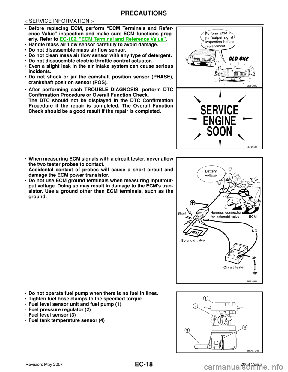
•Before replacing ECM, perform “ECM Terminals and Refer-
ence Value” inspection and make sure ECM functions prop-
erly. Refer to EC-102, "
ECM Terminal and Reference Value".
•Handle mass air flow sensor carefully to avoid damage.
•Do not disassemble mass air flow sensor.
•Do not clean mass air flow sensor with any type of detergent.
•Do not disassemble electric throttle control actuator.
•Even a slight leak in the air intake system can cause serious
incidents.
•Do not shock or jar the camshaft position sensor (PHASE),
crankshaft position sensor (POS).
•After performing each TROUBLE DIAGNOSIS, perform DTC
Confirmation Procedure or Overall Function Check.
The DTC should not be displayed in the DTC Confirmation
Procedure if the repair is completed. The Overall Function
Check should be a good result if the repair is completed.
•When measuring ECM signals with a circuit tester, never allow
the two tester probes to contact.
Accidental contact of probes will cause a short circuit and
damage the ECM power transistor.
•Do not use ECM ground terminals when measuring input/out-
put voltage. Doing so may result in damage to the ECM's tran-
sistor. Use a ground other than ECM terminals, such as the
ground.
•Do not operate fuel pump when there is no fuel in lines.
•Tighten fuel hose clamps to the specified torque.
-Fuel level sensor unit and fuel pump (1)
-Fuel pressure regulator (2)
-Fuel level sensor (3)
-Fuel tank temperature sensor (4)
MEF040D
SEF217U
SEF348N
BBIA0704E
Page 1094 of 2771
EC-20
< SERVICE INFORMATION >
PREPARATION
PREPARATION
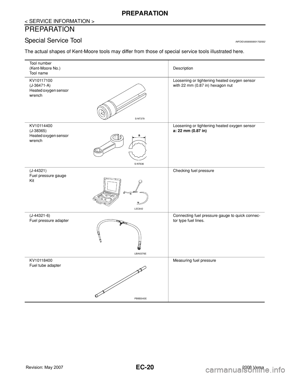
Special Service ToolINFOID:0000000001702552
The actual shapes of Kent-Moore tools may differ from those of special service tools illustrated here.
Tool number
(Kent-Moore No.)
Tool nameDescription
KV10117100
(J-36471-A)
Heated oxygen sensor
wrenchLoosening or tightening heated oxygen sensor
with 22 mm (0.87 in) hexagon nut
KV10114400
(J-38365)
Heated oxygen sensor
wrenchLoosening or tightening heated oxygen sensor
a: 22 mm (0.87 in)
(J-44321)
Fuel pressure gauge
KitChecking fuel pressure
(J-44321-6)
Fuel pressure adapterConnecting fuel pressure gauge to quick connec-
tor type fuel lines.
KV10118400
Fuel tube adapterMeasuring fuel pressure
S-NT379
S-NT636
LEC642
LBIA0376E
PBIB3043E
Page 1095 of 2771
PREPARATION
EC-21
< SERVICE INFORMATION >
C
D
E
F
G
H
I
J
K
L
MA
EC
N
P O
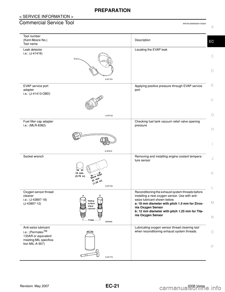
Commercial Service ToolINFOID:0000000001702553
Tool number
(Kent-Moore No.)
Tool nameDescription
Leak detector
i.e.: (J-41416)Locating the EVAP leak
EVAP service port
adapter
i.e.: (J-41413-OBD)Applying positive pressure through EVAP service
port
Fuel filler cap adapter
i.e.: (MLR-8382)Checking fuel tank vacuum relief valve opening
pressure
Socket wrench Removing and installing engine coolant tempera-
ture sensor
Oxygen sensor thread
cleaner
i.e.: (J-43897-18)
(J-43897-12)Reconditioning the exhaust system threads before
installing a new oxygen sensor. Use with anti-
seize lubricant shown below.
a: 18 mm diameter with pitch 1.5 mm for Zirco-
nia Oxygen Sensor
b: 12 mm diameter with pitch 1.25 mm for Tita-
nia Oxygen Sensor
Anti-seize lubricant
i.e.: (Permatex
TM
133AR or equivalent
meeting MIL specifica-
tion MIL-A-907)Lubricating oxygen sensor thread cleaning tool
when reconditioning exhaust system threads.
S-NT703
S-NT704
S-NT815
S-NT705
AEM488
S-NT779
Page 1096 of 2771
EC-22
< SERVICE INFORMATION >
ENGINE CONTROL SYSTEM
ENGINE CONTROL SYSTEM
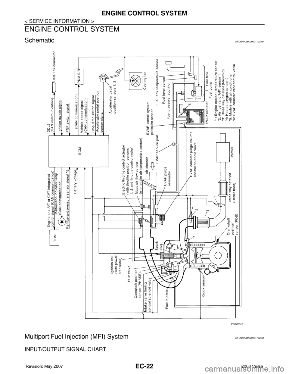
SchematicINFOID:0000000001702554
Multiport Fuel Injection (MFI) SystemINFOID:0000000001702555
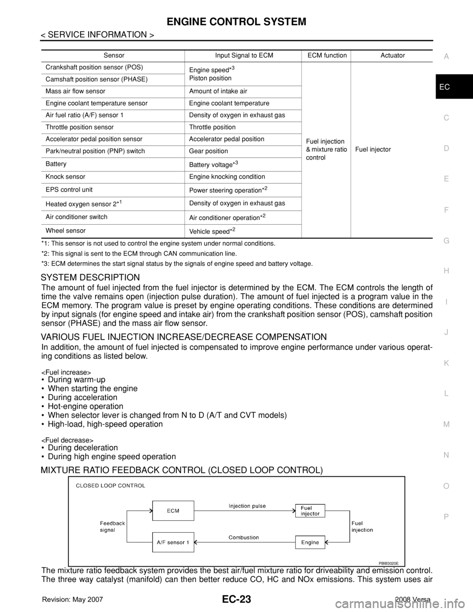
INPUT/OUTPUT SIGNAL CHART
PBIB3331E
Page 1097 of 2771
ENGINE CONTROL SYSTEM
EC-23
< SERVICE INFORMATION >
C
D
E
F
G
H
I
J
K
L
MA
EC
N
P O
*1: This sensor is not used to control the engine system under normal conditions.
*2: This signal is sent to the ECM through CAN communication line.
*3: ECM determines the start signal status by the signals of engine speed and battery voltage.
SYSTEM DESCRIPTION
The amount of fuel injected from the fuel injector is determined by the ECM. The ECM controls the length of
time the valve remains open (injection pulse duration). The amount of fuel injected is a program value in the
ECM memory. The program value is preset by engine operating conditions. These conditions are determined
by input signals (for engine speed and intake air) from the crankshaft position sensor (POS), camshaft position
sensor (PHASE) and the mass air flow sensor.
VARIOUS FUEL INJECTION INCREASE/DECREASE COMPENSATION
In addition, the amount of fuel injected is compensated to improve engine performance under various operat-
ing conditions as listed below.
• When starting the engine
• During acceleration
• Hot-engine operation
• When selector lever is changed from N to D (A/T and CVT models)
• High-load, high-speed operation
• During deceleration
• During high engine speed operation
MIXTURE RATIO FEEDBACK CONTROL (CLOSED LOOP CONTROL)
The mixture ratio feedback system provides the best air/fuel mixture ratio for driveability and emission control.
The three way catalyst (manifold) can then better reduce CO, HC and NOx emissions. This system uses air
Sensor Input Signal to ECM ECM function Actuator
Crankshaft position sensor (POS)
Engine speed*
3
Piston position
Fuel injection
& mixture ratio
controlFuel injector Camshaft position sensor (PHASE)
Mass air flow sensor Amount of intake air
Engine coolant temperature sensor Engine coolant temperature
Air fuel ratio (A/F) sensor 1 Density of oxygen in exhaust gas
Throttle position sensor Throttle position
Accelerator pedal position sensor Accelerator pedal position
Park/neutral position (PNP) switch Gear position
Battery
Battery voltage*
3
Knock sensor Engine knocking condition
EPS control unit
Power steering operation*
2
Heated oxygen sensor 2*1Density of oxygen in exhaust gas
Air conditioner switch
Air conditioner operation*
2
Wheel sensor
Vehicle speed*2
PBIB3020E
Page 1098 of 2771
EC-24
< SERVICE INFORMATION >
ENGINE CONTROL SYSTEM
fuel ratio (A/F) sensor 1 in the exhaust manifold to monitor whether the engine operation is rich or lean. The
ECM adjusts the injection pulse width according to the sensor voltage signal. For more information about air
fuel ratio (A/F) sensor 1, refer to EC-213
. This maintains the mixture ratio within the range of stoichiometric
(ideal air/fuel mixture).
This stage is referred to as the closed loop control condition.
Heated oxygen sensor 2 is located downstream of the three way catalyst (manifold). Even if the switching
characteristics of air fuel ratio (A/F) sensor 1 shift, the air/fuel ratio is controlled to stoichiometric by the signal
from heated oxygen sensor 2.
Open Loop Control
The open loop system condition refers to when the ECM detects any of the following conditions. Feedback
control stops in order to maintain stabilized fuel combustion.
• Deceleration and acceleration
• High-load, high-speed operation
• Malfunction of air fuel ratio (A/F) sensor 1 or its circuit
• Insufficient activation of air fuel ratio (A/F) sensor 1 at low engine coolant temperature
• High engine coolant temperature
• During warm-up
• After shifting from N to D (A/T and CVT models)
• When starting the engine
MIXTURE RATIO SELF-LEARNING CONTROL
The mixture ratio feedback control system monitors the mixture ratio signal transmitted from air fuel ratio (A/F)
sensor 1. This feedback signal is then sent to the ECM. The ECM controls the basic mixture ratio as close to
the theoretical mixture ratio as possible. However, the basic mixture ratio is not necessarily controlled as orig-
inally designed. Both manufacturing differences (i.e., mass air flow sensor hot wire) and characteristic
changes during operation (i.e., fuel injector clogging) directly affect mixture ratio.
Accordingly, the difference between the basic and theoretical mixture ratios is monitored in this system. This is
then computed in terms of “injection pulse duration” to automatically compensate for the difference between
the two ratios.
“Fuel trim” refers to the feedback compensation value compared against the basic injection duration. Fuel trim
includes short term fuel trim and long term fuel trim.
“Short term fuel trim” is the short-term fuel compensation used to maintain the mixture ratio at its theoretical
value. The signal from air fuel ratio (A/F) sensor 1 indicates whether the mixture ratio is RICH or LEAN com-
pared to the theoretical value. The signal then triggers a reduction in fuel volume if the mixture ratio is rich, and
an increase in fuel volume if it is lean.
“Long term fuel trim” is overall fuel compensation carried out long-term to compensate for continual deviation
of the short term fuel trim from the central value. Such deviation will occur due to individual engine differences,
wear over time and changes in the usage environment.
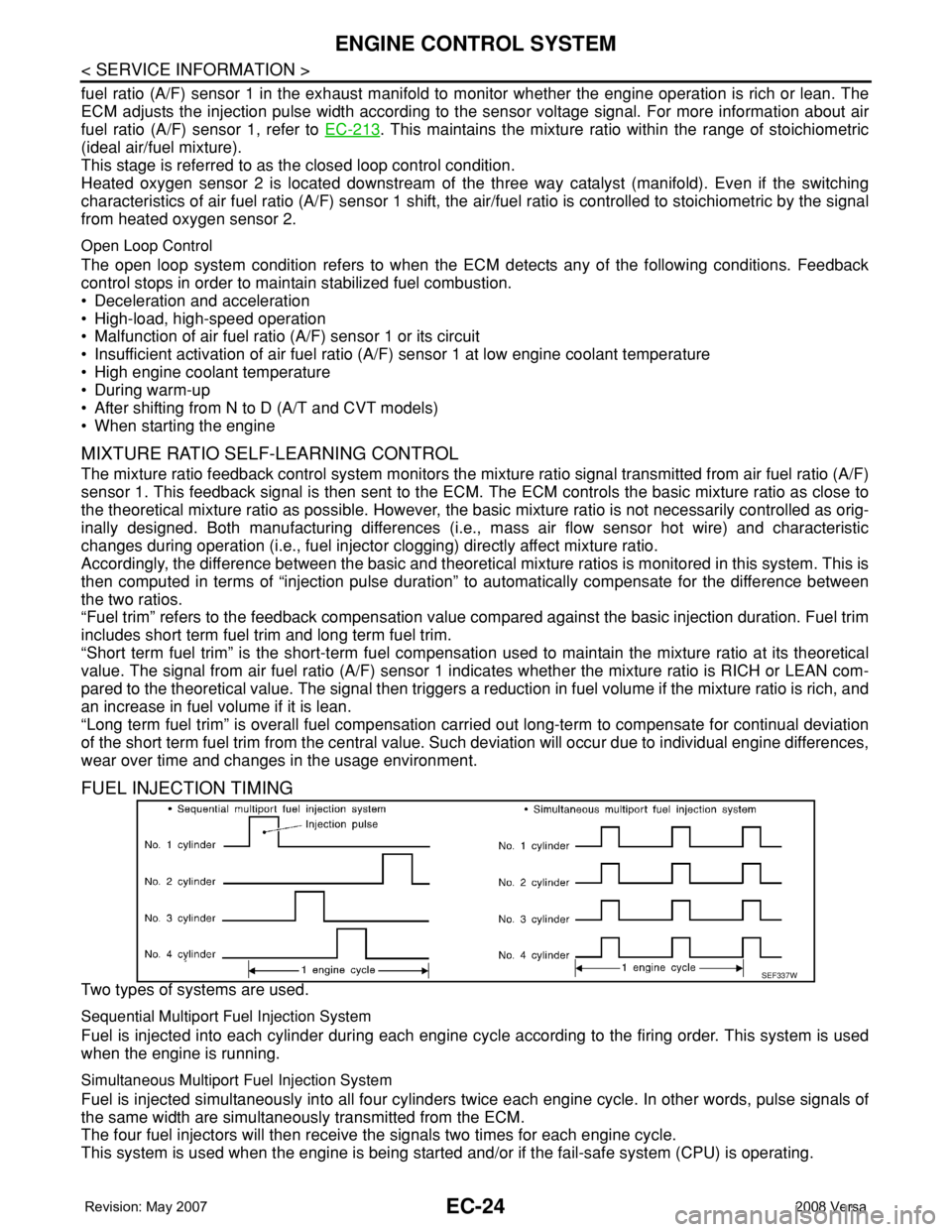
FUEL INJECTION TIMING
Two types of systems are used.
Sequential Multiport Fuel Injection System
Fuel is injected into each cylinder during each engine cycle according to the firing order. This system is used
when the engine is running.
Simultaneous Multiport Fuel Injection System
Fuel is injected simultaneously into all four cylinders twice each engine cycle. In other words, pulse signals of
the same width are simultaneously transmitted from the ECM.
The four fuel injectors will then receive the signals two times for each engine cycle.
This system is used when the engine is being started and/or if the fail-safe system (CPU) is operating.
SEF337W