Instrument panel NISSAN TIIDA 2008 Service Service Manual
[x] Cancel search | Manufacturer: NISSAN, Model Year: 2008, Model line: TIIDA, Model: NISSAN TIIDA 2008Pages: 2771, PDF Size: 60.61 MB
Page 1989 of 2771

INSTRUMENT PANEL ASSEMBLY
IP-23
< ON-VEHICLE REPAIR >
C
D
E
F
G
H
J
K
L
MA
B
IP
N
O
P
12. Disengage console mask cover metal clips and pawls, and then
remove console mask cover (with armrest).
13. Disengage rear cup holder metal clips and pawls (without arm-
rest).
14. Remover rear cup holder (without armrest).
15. Remove console body assembly screws and nut.
16. Disconnect harness connector, and then remove console body assembly.
17. Remove both of the instrument lower cover LH and RH clips.
18. Disengage instrument lower cover LH and RH metal clips and
remove both of the instrument lower cover LH and RH.
19. Remove screws and then remove center console.
Installation
Installation is in the reverse order of removal.
Disassembly and AssemblyINFOID:0000000001704253
GLOVE BOX ASSEMBLY
PIIB6387E
PIIB6388E
PIIB2882J
Page 1990 of 2771

IP-24
< ON-VEHICLE REPAIR >
INSTRUMENT PANEL ASSEMBLY
Disassembly
1. Remove screws of damper, and then remove damper.
2. Remove screws of glove box striker, and then remove glove box striker.
3. Remove screws of glove box latch, and then remove glove box latch.
Assembly
Assembly is in the reverse order of disassembly.
CENTER CONSOLE ASSEMBLY
1. Glove box striker 2. Glove box 3. Glove box latch
4. Damper
LIIA2555E
Page 1991 of 2771
INSTRUMENT PANEL ASSEMBLY
IP-25
< ON-VEHICLE REPAIR >
C
D
E
F
G
H
J
K
L
MA
B
IP
N
O
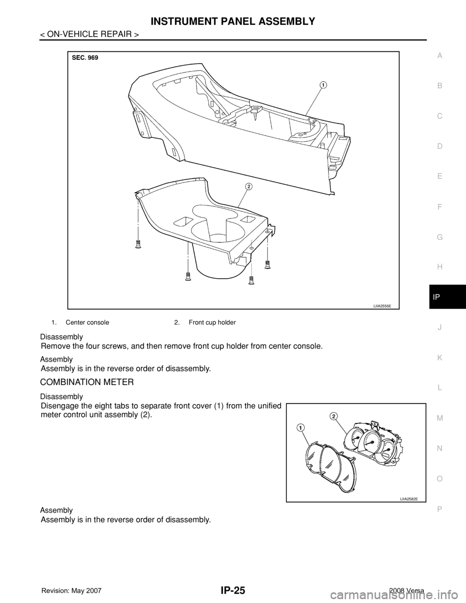
P Disassembly
Remove the four screws, and then remove front cup holder from center console.
Assembly
Assembly is in the reverse order of disassembly.
COMBINATION METER
Disassembly
Disengage the eight tabs to separate front cover (1) from the unified
meter control unit assembly (2).
Assembly
Assembly is in the reverse order of disassembly.
1. Center console 2. Front cup holder
LIIA2556E
LIIA2582E
Page 2393 of 2771
CONTROLLER
MTC-55
< SERVICE INFORMATION >
C
D
E
F
G
H
I
K
L
MA
B
MTC
N
O
P
CONTROLLER
Removal and InstallationINFOID:0000000001704309
REMOVAL
1. Remove cluster lid C and instrument finisher D. Refer to IP-10 .
2. Remove intake door lever knob. Refer to MTC-56, "
Disassembly
and Assembly" .
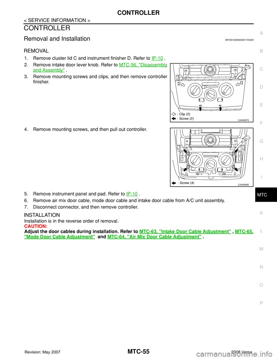
3. Remove mounting screws and clips, and then remove controller
finisher.
4. Remove mounting screws, and then pull out controller.
5. Remove instrument panel and pad. Refer to IP-10
.
6. Remove air mix door cable, mode door cable and intake door cable from A/C unit assembly.
7. Disconnect connector, and then remove controller.
INSTALLATION
Installation is in the reverse order of removal.
CAUTION:
Adjust the door cables during installation. Refer to MTC-63, "
Intake Door Cable Adjustment" , MTC-65,
"Mode Door Cable Adjustment" and MTC-64, "Air Mix Door Cable Adjustment" .
ZJIA0697E
ZJIA0698E
Page 2397 of 2771
A/C UNIT ASSEMBLY
MTC-59
< SERVICE INFORMATION >
C
D
E
F
G
H
I
K
L
MA
B
MTC
N
O
P
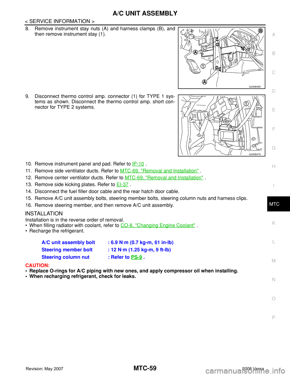
8. Remove instrument stay nuts (A) and harness clamps (B), and
then remove instrument stay (1).
9. Disconnect thermo control amp. connector (1) for TYPE 1 sys-
tems as shown. Disconnect the thermo control amp. short con-
nector for TYPE 2 systems.
10. Remove instrument panel and pad. Refer to IP-10
.
11. Remove side ventilator ducts. Refer to MTC-69, "
Removal and Installation" .
12. Remove center ventilator ducts. Refer to MTC-69, "
Removal and Installation" .
13. Remove side kicking plates. Refer to EI-37
.
14. Disconnect the fuel filler door cable and the rear hatch door cable.
15. Remove A/C unit assembly bolts, steering member bolts, steering column nuts and harness clips.
16. Remove steering member, and then remove A/C unit assembly.
INSTALLATION
Installation is in the reverse order of removal.
• When filling radiator with coolant, refer to CO-8, "
Changing Engine Coolant" .
• Recharge the refrigerant.
CAUTION:
• Replace O-rings for A/C piping with new ones, and apply compressor oil when installing.
• When recharging refrigerant, check for leaks.
SJIA0646E
SJIA0647E
A/C unit assembly bolt : 6.9 N·m (0.7 kg-m, 61 in-lb)
Steering member bolt : 12 N·m (1.25 kg-m, 9 ft-lb)
Steering column nut : Refer to PS-9
.
Page 2400 of 2771
MTC-62
< SERVICE INFORMATION >
BLOWER MOTOR
BLOWER MOTOR
Removal and InstallationINFOID:0000000001704314
REMOVAL
1. Remove instrument panel and pad. Refer to IP-10.
2. Remove side ventilator duct (right). Refer to MTC-69, "
Removal and Installation".
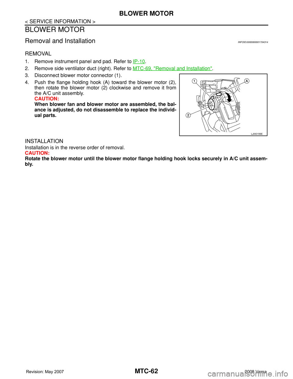
3. Disconnect blower motor connector (1).
4. Push the flange holding hook (A) toward the blower motor (2),
then rotate the blower motor (2) clockwise and remove it from
the A/C unit assembly.
CAUTION:
When blower fan and blower motor are assembled, the bal-
ance is adjusted, do not disassemble to replace the individ-
ual parts.
INSTALLATION
Installation is in the reverse order of removal.
CAUTION:
Rotate the blower motor until the blower motor flange holding hook locks securely in A/C unit assem-
bly.
LJIA0199E
Page 2407 of 2771

DUCTS AND GRILLES
MTC-69
< SERVICE INFORMATION >
C
D
E
F
G
H
I
K
L
MA
B
MTC
N
O
P
DUCTS AND GRILLES
Removal and InstallationINFOID:0000000001704321
Floor Ducts - Canada Only
1. Side defroster duct (right) 2. Defroster nozzle 3. Side defroster duct (left)
4. Side defroster grille (left) 5. Instrument side panel (left) 6. Instrument panel and pad
7. Side ventilator assembly (left) 8. Cluster lid C 9. Side ventilator assembly (right)
10. Instrument finisher E 11. Instrument side panel (right) 12. Side defroster grille (right)
13. Side ventilator duct (right) 14. Center ventilator duct (right) 15. Center ventilator duct (left)
16. Side ventilator duct (left)
SJIA0657E
WJIA2198E
Page 2409 of 2771

DUCTS AND GRILLES
MTC-71
< SERVICE INFORMATION >
C
D
E
F
G
H
I
K
L
MA
B
MTC
N
O
P Removal
1. Remove instrument upper finisher. Refer to IP-10.
2. Remove screws and then remove side defroster duct (RH) and side defroster duct (LH).
3. Remove screws, and then remove defroster nozzle.
Installation
Installation is in the reverse order of removal.
SIDE VENTILATOR DUCTS
Removal
1. Remove instrument panel and pad. Refer to IP-10.
2. Remove screws (A), and then remove side ventilator duct (left)
(1).
3. Remove screw (A) and clip (B), and then remove side ventilator
duct (right) (1).
Installation
Installation is in the reverse order of removal.
1. Side defroster duct (RH) 2. Side defroster duct (LH) 3. Defroster nozzle
A. Side defroster duct screw B. Defroster nozzle screw
WJIA2199E
SJIA0661E
SJIA0662E
Page 2410 of 2771

MTC-72
< SERVICE INFORMATION >
DUCTS AND GRILLES
CENTER VENTILATOR DUCTS
Removal
1. Remove instrument panel & pad. Refer to IP-10.
2. Remove screws (A), and then remove center ventilator ducts
(1).
Installation
Installation is in the reverse order of removal.
SIDE FOOT DUCTS
NOTE:
The side foot ducts are part of the A/C unit assembly case.
Removal
1. Remove A/C unit assembly. Refer to MTC-58.
2. Remove screws (A), and then remove side foot duct (LH) (1).
3. Remove screws (A), and then remove side foot duct (RH) (1).
Installation
Installation is in the reverse order of removal.
FLOOR DUCTS
Removal
1. Remove front seats and center console assembly. Refer to SE-10 and IP-10.
SJIA0663E
SJIA0664E
SJIA0665E
Page 2472 of 2771
HARNESS
PG-39
< SERVICE INFORMATION >
C
D
E
F
G
H
I
J
L
MA
B
PG
N
O
P
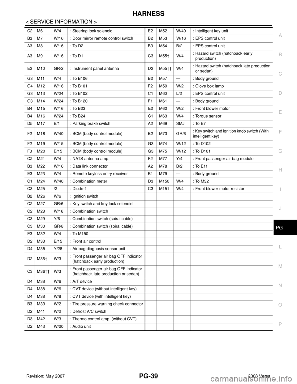
C2 M6 W/4 : Steering lock solenoid E2 M52 W/40 : Intelligent key unit
B3 M7 W/16 : Door mirror remote control switch B2 M53 W/16 : EPS control unit
A3 M8 W/16 : To D2 B3 M54 B/2 : EPS control unit
A3 M9 W/16 : To D1 C3 M55† W/4: Hazard switch (hatchback early
production)
E2 M10 GR/2 : Instrument panel antenna D2 M55†† W/4: Hazard switch (hatchback late production
or sedan)
G3 M11 W/4 : To B106 B2 M57 — : Body ground
G4 M12 W/16 : To B101 F2 M59 W/2 : Glove box lamp
G3 M13 W/24 : To B102 C1 M60 L/2 : EPS control unit
G3 M14 W/24 : To B120 F1 M61 — : Body ground
B4 M15 W/16 : To B23 E2 M62 W/2 : Front blower motor
B4 M16 W/24 : To B24 C1 M63 W/4 : Torque sensor
D5 M17 B/1 : Parking brake switch A2 M69 SMJ : To E7
F2 M18 W/40 : BCM (body control module) B2 M73 GR/6: Key switch and ignition knob switch (With
intelligent key)
F2 M19 W/15 : BCM (body control module) G3 M74 W/12 : To D102
F3 M20 B/15 : BCM (body control module) G3 M75 W/12 : To D101
C2 M21 W/4 : NATS antenna amp. F2 M77 Y/4 : Front passenger air bag module
B3 M22 W/16 : Data link connector A2 M78 B/2 : To E11
E3 M23 W/4 : Remote keyless entry receiver B1 M79 — : Body ground
C1 M24 W/40 : Combination meter D3 M150 W/4 : To M32
C3 M25 /2 : Diode-1 C3 M151 W/4 : Front blower motor resistor
B2 M26 W/6 : Ignition switch
C2 M27 GR/6 : Key switch and key lock solenoid
C2 M28 W/16 : Combination switch
C3 M29 Y/6 : Combination switch (spiral cable)
C3 M30 GR/8 : Combination switch (spiral cable)
E3 M32 W/4 : To M150
D2 M33 B/15 : Front air control
D4 M35 Y/28 : Air bag diagnosis sensor unit
D2 M36† W/3: Front passenger air bag OFF indicator
(hatchback early production)
C3 M36†† W/3: Front passenger air bag OFF indicator
(hatchback late production or sedan)
D4 M38 W/6 : A/T device
D4 M38 W/6 : CVT device (without intelligent key)
D4 M38 W/8 : CVT device (with intelligent key)
B3 M39 W/2 : Tire pressure warning check connector
D2 M41 W/2 : Defrost A/C switch
D3 M42 W/3 : Thermo control amp. (without CVT)
D2 M43 W/20 : Audio unit