EI- NISSAN TIIDA 2008 Service Repair Manual
[x] Cancel search | Manufacturer: NISSAN, Model Year: 2008, Model line: TIIDA, Model: NISSAN TIIDA 2008Pages: 2771, PDF Size: 60.61 MB
Page 228 of 2771
AT-216
< SERVICE INFORMATION >
ON-VEHICLE SERVICE
ON-VEHICLE SERVICE
Control Valve Assembly and AccumulatorsINFOID:0000000001703366
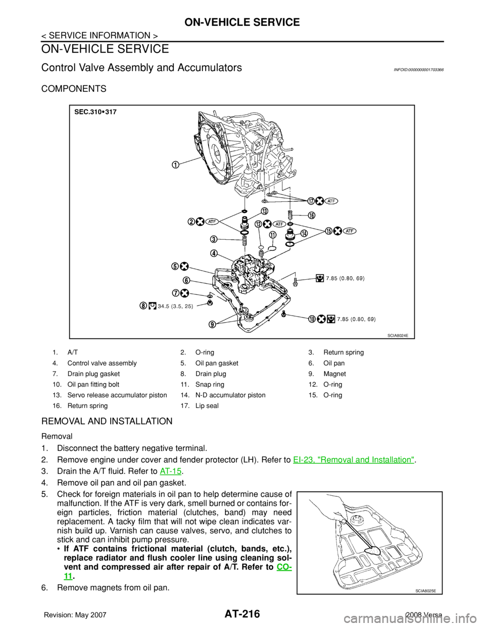
COMPONENTS
REMOVAL AND INSTALLATION
Removal
1. Disconnect the battery negative terminal.
2. Remove engine under cover and fender protector (LH). Refer to EI-23, "
Removal and Installation".
3. Drain the A/T fluid. Refer to AT- 1 5
.
4. Remove oil pan and oil pan gasket.
5. Check for foreign materials in oil pan to help determine cause of
malfunction. If the ATF is very dark, smell burned or contains for-
eign particles, friction material (clutches, band) may need
replacement. A tacky film that will not wipe clean indicates var-
nish build up. Varnish can cause valves, servo, and clutches to
stick and can inhibit pump pressure.
•If ATF contains frictional material (clutch, bands, etc.),
replace radiator and flush cooler line using cleaning sol-
vent and compressed air after repair of A/T. Refer to CO-
11.
6. Remove magnets from oil pan.
1. A/T 2. O-ring 3. Return spring
4. Control valve assembly 5. Oil pan gasket 6. Oil pan
7. Drain plug gasket 8. Drain plug 9. Magnet
10. Oil pan fitting bolt 11. Snap ring 12. O-ring
13. Servo release accumulator piston 14. N-D accumulator piston 15. O-ring
16. Return spring 17. Lip seal
SCIA8024E
SCIA8025E
Page 395 of 2771
AV-36
< SERVICE INFORMATION >
AUDIO
OK or NG
OK >> Replace subwoofer. Refer to AV-36, "Removal and Installation" .
NG >> Replace audio unit. Refer to AV-36, "
Removal and Installation" .
Removal and InstallationINFOID:0000000001704674
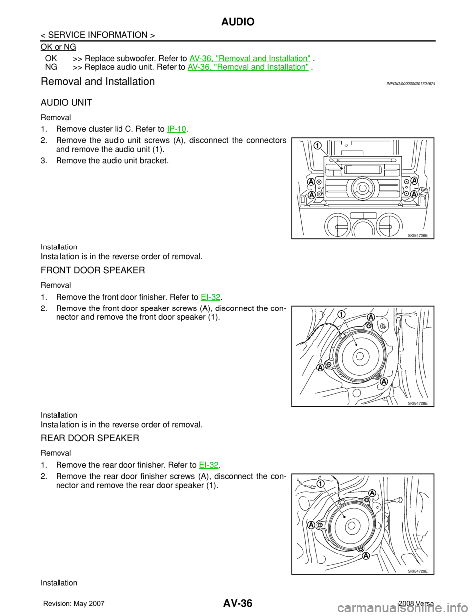
AUDIO UNIT
Removal
1. Remove cluster lid C. Refer to IP-10.
2. Remove the audio unit screws (A), disconnect the connectors
and remove the audio unit (1).
3. Remove the audio unit bracket.
Installation
Installation is in the reverse order of removal.
FRONT DOOR SPEAKER
Removal
1. Remove the front door finisher. Refer to EI-32.
2. Remove the front door speaker screws (A), disconnect the con-
nector and remove the front door speaker (1).
Installation
Installation is in the reverse order of removal.
REAR DOOR SPEAKER
Removal
1. Remove the rear door finisher. Refer to EI-32.
2. Remove the rear door finisher screws (A), disconnect the con-
nector and remove the rear door speaker (1).
Installation
SKIB4726E
SKIB4728E
SKIB4729E
Page 396 of 2771

AUDIO
AV-37
< SERVICE INFORMATION >
C
D
E
F
G
H
I
J
L
MA
B
AV
N
O
P
Installation is in the reverse order of removal.
TWEETER
Removal
1. Remove the front pillar garnish. Refer to EI-37.
2. Remove the tweeter screw (A), disconnect the connector and
remove the tweeter (1).
Installation
Installation is in the reverse order of removal.
SATELLITE RADIO TUNER
Hatchback
SKIB4730E
LKIA0767E
1. Bracket (upper) 2. Satellite radio tuner 3. Bracket (lower)
A. Screws B. Connector C. Satellite radio tuner bolts
⇒Front
Page 397 of 2771
AV-38
< SERVICE INFORMATION >
AUDIO
Sedan
Removal
1. For hatchback, remove the luggage side lower finisher (LH) (hatchback only). Refer to EI-51.
2. For sedan, remove the trunk side finisher (LH). Refer to EI-53, "
Removal and Installation".
3. For hatchback remove the subwoofer. Refer to "SUBWOOFER".
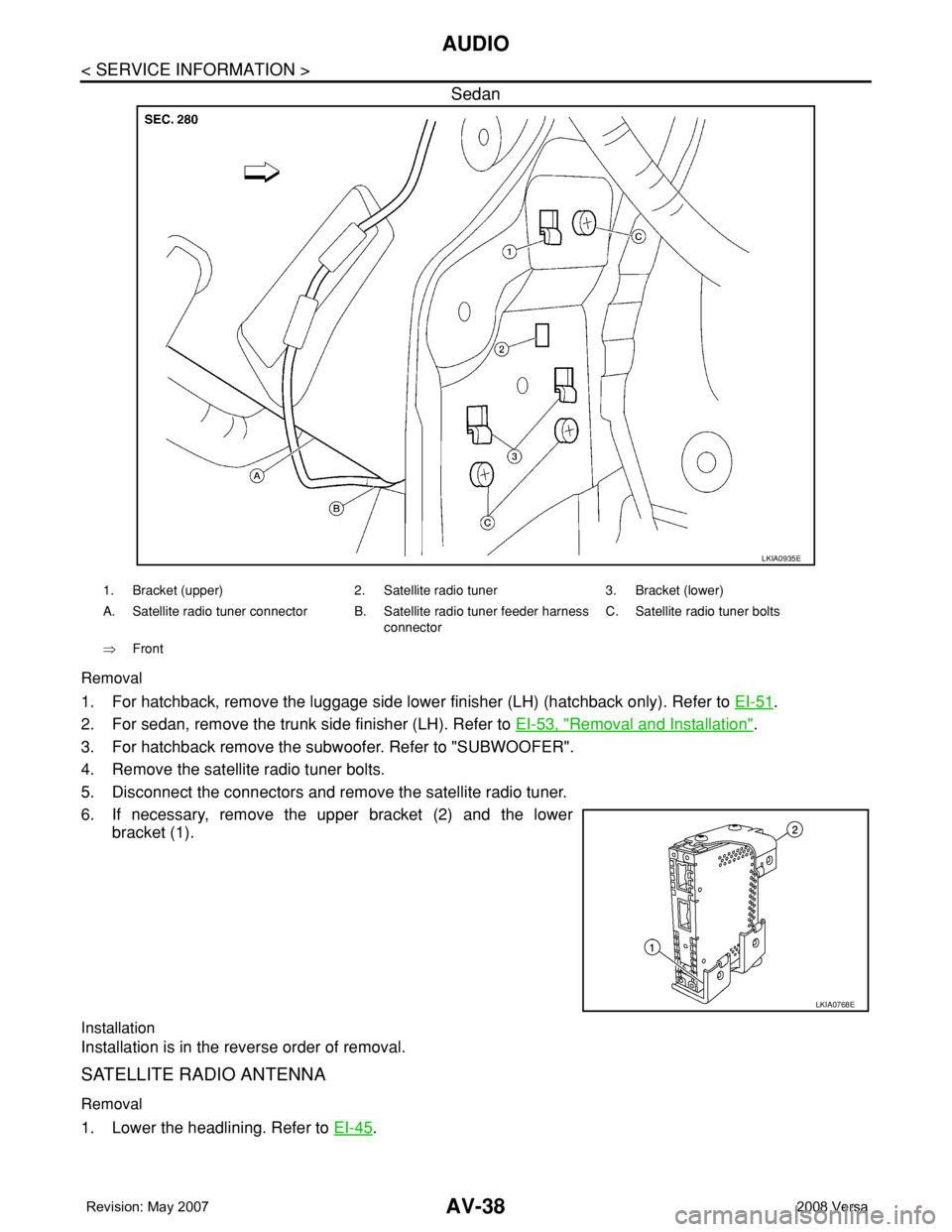
4. Remove the satellite radio tuner bolts.
5. Disconnect the connectors and remove the satellite radio tuner.
6. If necessary, remove the upper bracket (2) and the lower
bracket (1).
Installation
Installation is in the reverse order of removal.
SATELLITE RADIO ANTENNA
Removal
1. Lower the headlining. Refer to EI-45.
LKIA0935E
1. Bracket (upper) 2. Satellite radio tuner 3. Bracket (lower)
A. Satellite radio tuner connector B. Satellite radio tuner feeder harness
connectorC. Satellite radio tuner bolts
⇒Front
LKIA0768E
Page 399 of 2771

AV-40
< SERVICE INFORMATION >
AUDIO
Removal
1. Remove the luggage side lower finisher (LH). Refer to EI-51.
2. Remove the subwoofer bolts.
3. Disconnect the connector and remove the subwoofer.
Installation
Installation is in the reverse order of removal.
1. Subwoofer A. Subwoofer bolts B. Connector
LKIA0770E
Page 400 of 2771
AUDIO ANTENNA
AV-41
< SERVICE INFORMATION >
C
D
E
F
G
H
I
J
L
MA
B
AV
N
O
P
AUDIO ANTENNA
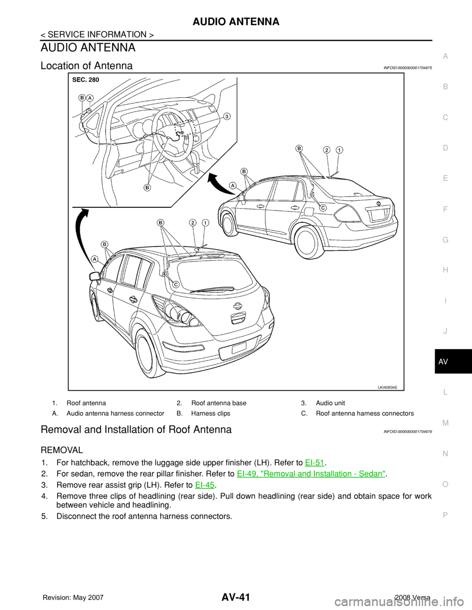
Location of AntennaINFOID:0000000001704675
Removal and Installation of Roof AntennaINFOID:0000000001704676
REMOVAL
1. For hatchback, remove the luggage side upper finisher (LH). Refer to EI-51.
2. For sedan, remove the rear pillar finisher. Refer to EI-49, "
Removal and Installation - Sedan".
3. Remove rear assist grip (LH). Refer to EI-45
.
4. Remove three clips of headlining (rear side). Pull down headlining (rear side) and obtain space for work
between vehicle and headlining.
5. Disconnect the roof antenna harness connectors.
LKIA0934E
1. Roof antenna 2. Roof antenna base 3. Audio unit
A. Audio antenna harness connector B. Harness clips C. Roof antenna harness connectors
Page 415 of 2771
AV-56
< SERVICE INFORMATION >
TELEPHONE
Removal
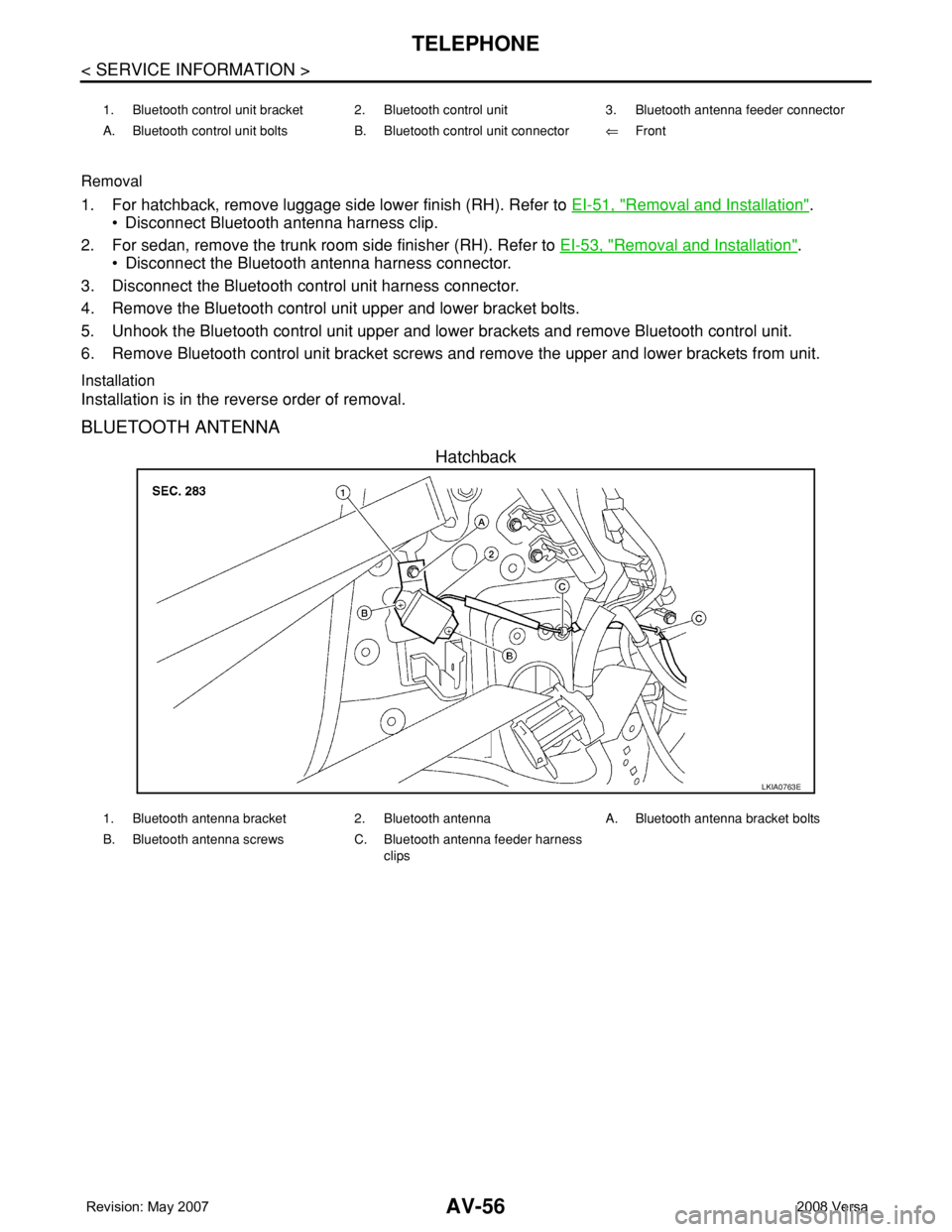
1. For hatchback, remove luggage side lower finish (RH). Refer to EI-51, "Removal and Installation".
• Disconnect Bluetooth antenna harness clip.
2. For sedan, remove the trunk room side finisher (RH). Refer to EI-53, "
Removal and Installation".
• Disconnect the Bluetooth antenna harness connector.
3. Disconnect the Bluetooth control unit harness connector.
4. Remove the Bluetooth control unit upper and lower bracket bolts.
5. Unhook the Bluetooth control unit upper and lower brackets and remove Bluetooth control unit.
6. Remove Bluetooth control unit bracket screws and remove the upper and lower brackets from unit.
Installation
Installation is in the reverse order of removal.
BLUETOOTH ANTENNA
Hatchback
1. Bluetooth control unit bracket 2. Bluetooth control unit 3. Bluetooth antenna feeder connector
A. Bluetooth control unit bolts B. Bluetooth control unit connector⇐Front
LKIA0763E
1. Bluetooth antenna bracket 2. Bluetooth antenna A. Bluetooth antenna bracket bolts
B. Bluetooth antenna screws C. Bluetooth antenna feeder harness
clips
Page 416 of 2771
TELEPHONE
AV-57
< SERVICE INFORMATION >
C
D
E
F
G
H
I
J
L
MA
B
AV
N
O
P
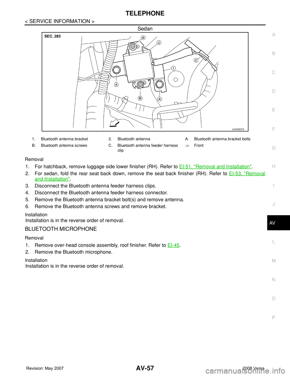
Sedan
Removal
1. For hatchback, remove luggage side lower finisher (RH). Refer to EI-51, "Removal and Installation".
2. For sedan, fold the rear seat back down, remove the seat back finisher (RH). Refer to EI-53, "
Removal
and Installation".
3. Disconnect the Bluetooth antenna feeder harness clips.
4. Disconnect the Bluetooth antenna feeder harness connector.
5. Remove the Bluetooth antenna bracket bolt(s) and remove antenna.
6. Remove the Bluetooth antenna screws and remove bracket.
Installation
Installation is in the reverse order of removal.
BLUETOOTH MICROPHONE
Removal
1. Remove over-head console assembly, roof finisher. Refer to EI-45.
2. Remove the Bluetooth microphone.
Installation
Installation is in the reverse order of removal.
LKIA0937E
1. Bluetooth antenna bracket 2. Bluetooth antenna A. Bluetooth antenna bracket bolts
B. Bluetooth antenna screws C. Bluetooth antenna feeder harness
clip⇒Front
Page 447 of 2771
HOOD
BL-13
< SERVICE INFORMATION >
C
D
E
F
G
H
J
K
L
MA
B
BL
N
O
P
HOOD
Fitting AdjustmentINFOID:0000000001703947
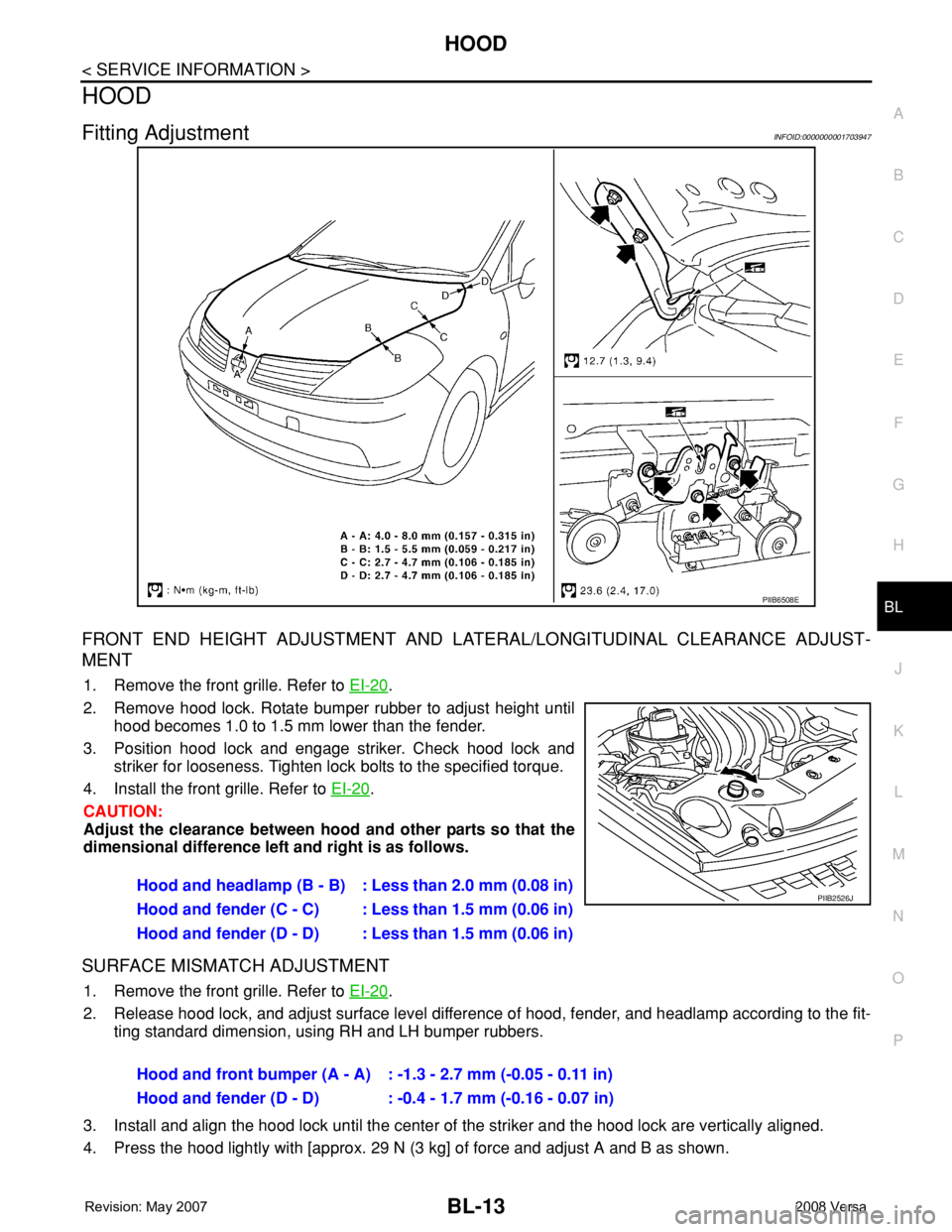
FRONT END HEIGHT ADJUSTMENT AND LATERAL/LONGITUDINAL CLEARANCE ADJUST-
MENT
1. Remove the front grille. Refer to EI-20.
2. Remove hood lock. Rotate bumper rubber to adjust height until
hood becomes 1.0 to 1.5 mm lower than the fender.
3. Position hood lock and engage striker. Check hood lock and
striker for looseness. Tighten lock bolts to the specified torque.
4. Install the front grille. Refer to EI-20
.
CAUTION:
Adjust the clearance between hood and other parts so that the
dimensional difference left and right is as follows.
SURFACE MISMATCH ADJUSTMENT
1. Remove the front grille. Refer to EI-20.
2. Release hood lock, and adjust surface level difference of hood, fender, and headlamp according to the fit-
ting standard dimension, using RH and LH bumper rubbers.
3. Install and align the hood lock until the center of the striker and the hood lock are vertically aligned.
4. Press the hood lightly with [approx. 29 N (3 kg] of force and adjust A and B as shown.
PIIB6508E
Hood and headlamp (B - B) : Less than 2.0 mm (0.08 in)
Hood and fender (C - C) : Less than 1.5 mm (0.06 in)
Hood and fender (D - D) : Less than 1.5 mm (0.06 in)PIIB2526J
Hood and front bumper (A - A) : -1.3 - 2.7 mm (-0.05 - 0.11 in)
Hood and fender (D - D) : -0.4 - 1.7 mm (-0.16 - 0.07 in)
Page 448 of 2771
BL-14
< SERVICE INFORMATION >
HOOD
5. After adjustment tighten lock bolts to the specified torque.
6. Install the front grille. Refer to EI-20
.
Removal and InstallationINFOID:0000000001703948
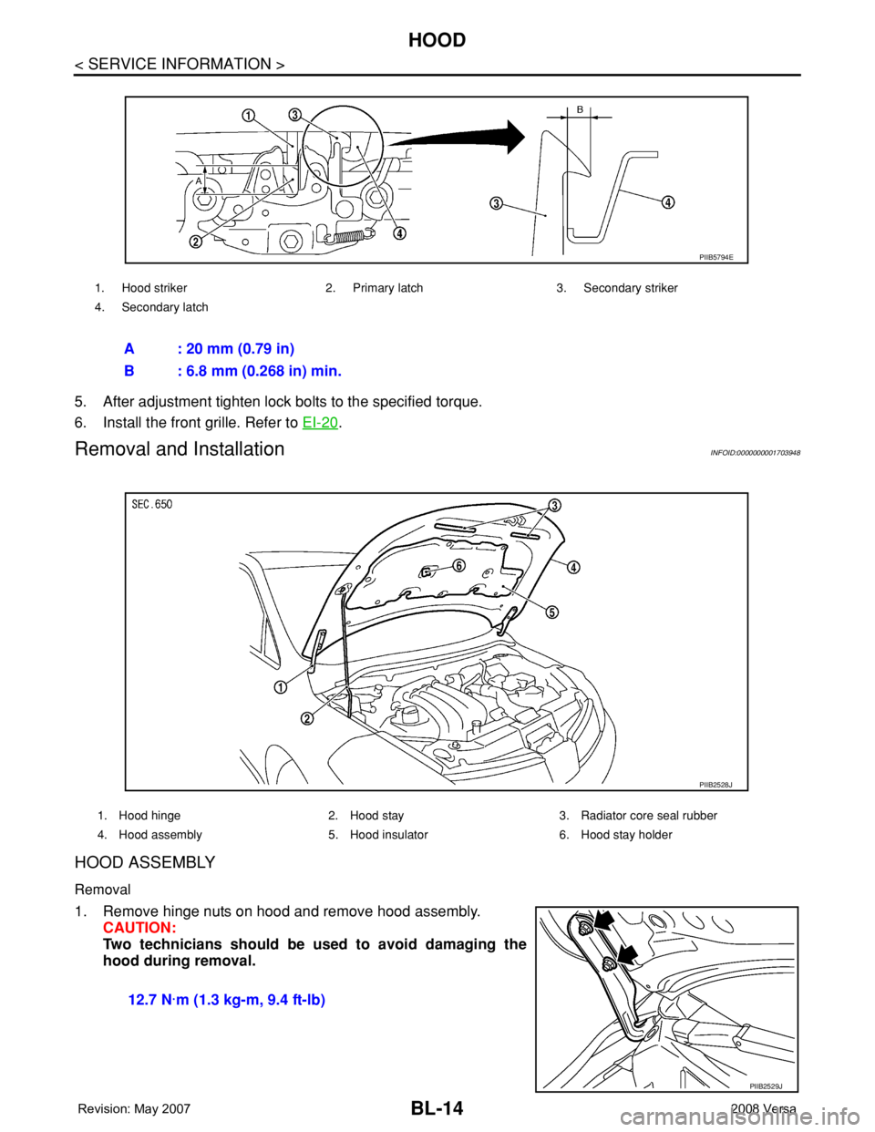
HOOD ASSEMBLY
Removal
1. Remove hinge nuts on hood and remove hood assembly.
CAUTION:
Two technicians should be used to avoid damaging the
hood during removal.
1. Hood striker 2. Primary latch 3. Secondary striker
4. Secondary latch
A : 20 mm (0.79 in)
B : 6.8 mm (0.268 in) min.
PIIB5794E
1. Hood hinge 2. Hood stay 3. Radiator core seal rubber
4. Hood assembly 5. Hood insulator 6. Hood stay holder
PIIB2528J
12.7 N·m (1.3 kg-m, 9.4 ft-lb)
PIIB2529J