FSU - 16 NISSAN TIIDA 2008 Service Repair Manual
[x] Cancel search | Manufacturer: NISSAN, Model Year: 2008, Model line: TIIDA, Model: NISSAN TIIDA 2008Pages: 2771, PDF Size: 60.61 MB
Page 1 of 2771
-1
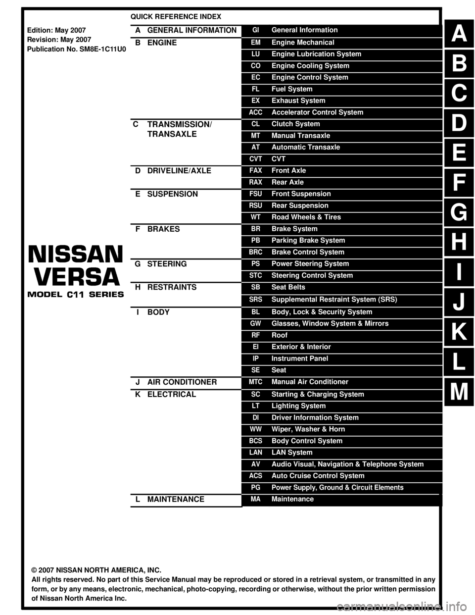
QUICK REFERENCE INDEX
AGENERAL INFORMATIONGIGeneral Information
BENGINEEMEngine Mechanical
LUEngine Lubrication System
COEngine Cooling System
ECEngine Control System
FLFuel System
EXExhaust System
ACCAccelerator Control System
CTRANSMISSION/
TRANSAXLECLClutch System
MTManual Transaxle
ATAutomatic Transaxle
CVTCVT
DDRIVELINE/AXLEFAXFront Axle
RAXRear Axle
ESUSPENSIONFSUFront Suspension
RSURear Suspension
WTRoad Wheels & Tires
FBRAKESBRBrake System
PBParking Brake System
BRCBrake Control System
GSTEERINGPSPower Steering System
STCSteering Control System
HRESTRAINTSSBSeat Belts
SRSSupplemental Restraint System (SRS)
IBODYBLBody, Lock & Security System
GWGlasses, Window System & Mirrors
RFRoof
EIExterior & Interior
IPInstrument Panel
SESeat
JAIR CONDITIONERMTCManual Air Conditioner
KELECTRICALSCStarting & Charging System
LTLighting System
DIDriver Information System
WWWiper, Washer & Horn
BCSBody Control System
LANLAN System
AVAudio Visual, Navigation & Telephone System
ACSAuto Cruise Control System
PGPower Supply, Ground & Circuit Elements
LMAINTENANCEMAMaintenance
Edition: May 2007
Revision: May 2007
Publication No. SM8E-1C11U0
B
D
© 2007 NISSAN NORTH AMERICA, INC.
All rights reserved. No part of this Service Manual may be reproduced or stored in a retrieval system, or transmitted in any
form, or by any means, electronic, mechanical, photo-copying, recording or otherwise, without the prior written permission
of Nissan North America Inc.
A
C
E
F
G
H
I
J
K
L
M
Page 735 of 2771
BR-4
< SERVICE INFORMATION >
NOISE, VIBRATION AND HARSHNESS (NVH) TROUBLESHOOTING
NOISE, VIBRATION AND HARSHNESS (NVH) TROUBLESHOOTING
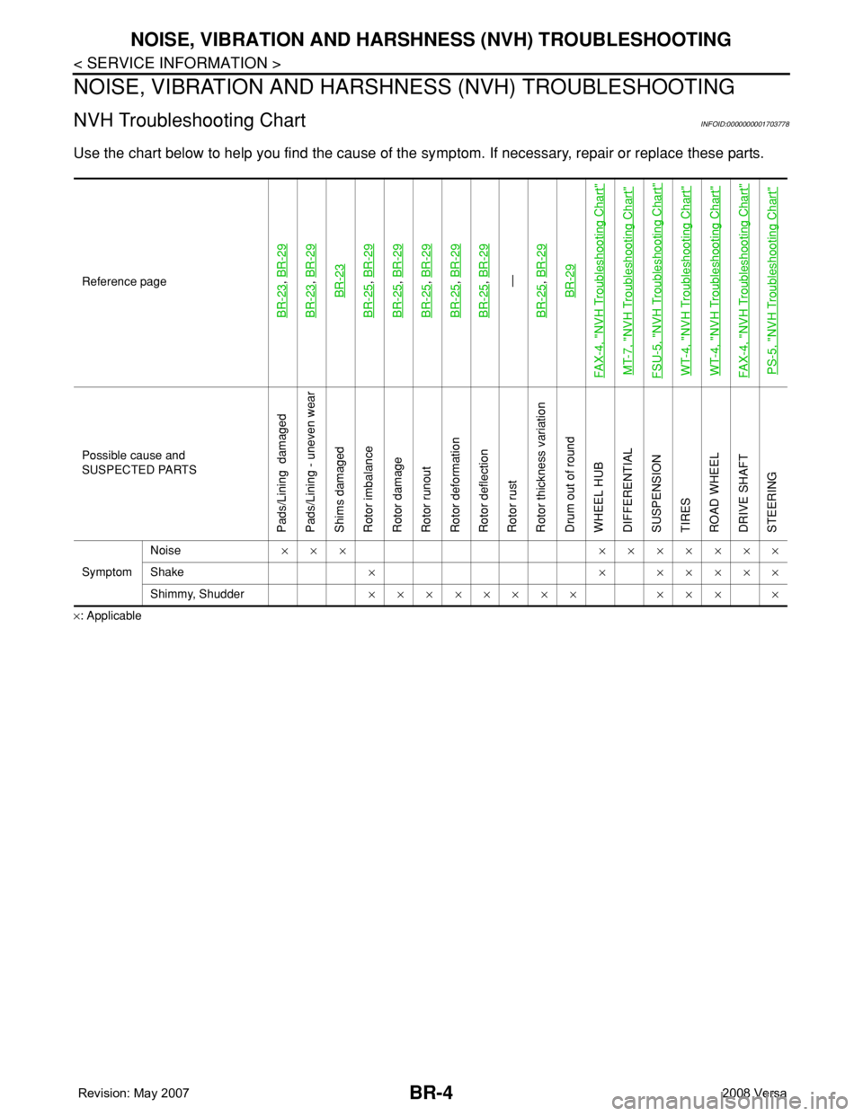
NVH Troubleshooting ChartINFOID:0000000001703778
Use the chart below to help you find the cause of the symptom. If necessary, repair or replace these parts.
×: ApplicableReference page
BR-23
, BR-29
BR-23
, BR-29BR-23
BR-25
, BR-29
BR-25
, BR-29
BR-25
, BR-29
BR-25
, BR-29
BR-25
, BR-29—
BR-25, BR-29BR-29
FAX-4, "
NVH Troubleshooting Chart
"
MT-7, "
NVH Troubleshooting Chart
"
FSU-5, "
NVH Troubleshooting Chart
"
WT-4, "
NVH Troubleshooting Chart
"
WT-4, "
NVH Troubleshooting Chart
"
FAX-4, "
NVH Troubleshooting Chart
"
PS-5, "
NVH Troubleshooting Chart
"
Possible cause and
SUSPECTED PARTS
Pads/Lining damaged
Pads/Lining - uneven wear
Shims damaged
Rotor imbalance
Rotor damage
Rotor runout
Rotor deformation
Rotor deflection
Rotor rust
Rotor thickness variation
Drum out of round
WHEEL HUB
DIFFERENTIAL
SUSPENSION
TIRES
ROAD WHEEL
DRIVE SHAFT
STEERING
SymptomNoise××× ×××××××
Shake× × ×××××
Shimmy, Shudder×××××××× ××× ×
Page 1800 of 2771
FAX-4
< SERVICE INFORMATION >
NOISE, VIBRATION AND HARSHNESS (NVH) TROUBLESHOOTING
NOISE, VIBRATION AND HARSHNESS (NVH) TROUBLESHOOTING
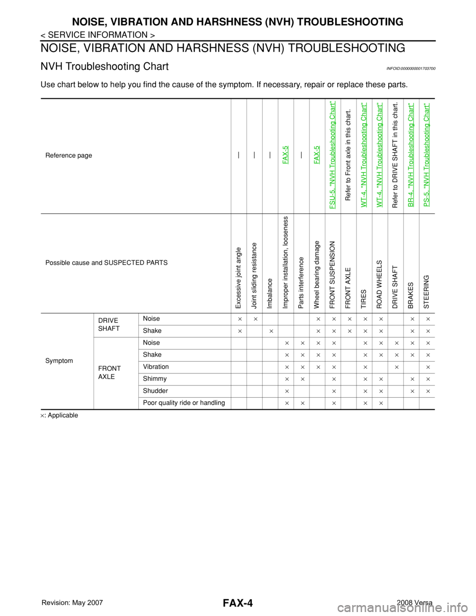
NVH Troubleshooting ChartINFOID:0000000001703700
Use chart below to help you find the cause of the symptom. If necessary, repair or replace these parts.
×: ApplicableReference page
—
—
—
FAX-5—
FAX-5
FSU-5, "
NVH Troubleshooting Chart
"
Refer to Front axle in this chart.
WT-4, "
NVH Troubleshooting Chart
"
WT-4, "
NVH Troubleshooting Chart
"
Refer to DRIVE SHAFT in this chart.
BR-4, "
NVH Troubleshooting Chart
"
PS-5, "
NVH Troubleshooting Chart
"
Possible cause and SUSPECTED PARTS
Excessive joint angle
Joint sliding resistance
Imbalance
Improper installation, looseness
Parts interference
Wheel bearing damage
FRONT SUSPENSION
FRONT AXLE
TIRES
ROAD WHEELS
DRIVE SHAFT
BRAKES
STEERING
SymptomDRIVE
SHAFTNoise×× ××××× ××
Shake× × ××××× ××
FRONT
AXLENoise×××× ×××××
Shake×××× ×××××
Vibration×××××××
Shimmy×××××××
Shudder× × ×× ××
Poor quality ride or handling×××××
Page 1803 of 2771
FRONT WHEEL HUB AND KNUCKLE
FAX-7
< SERVICE INFORMATION >
C
E
F
G
H
I
J
K
L
MA
B
FA X
N
O
P
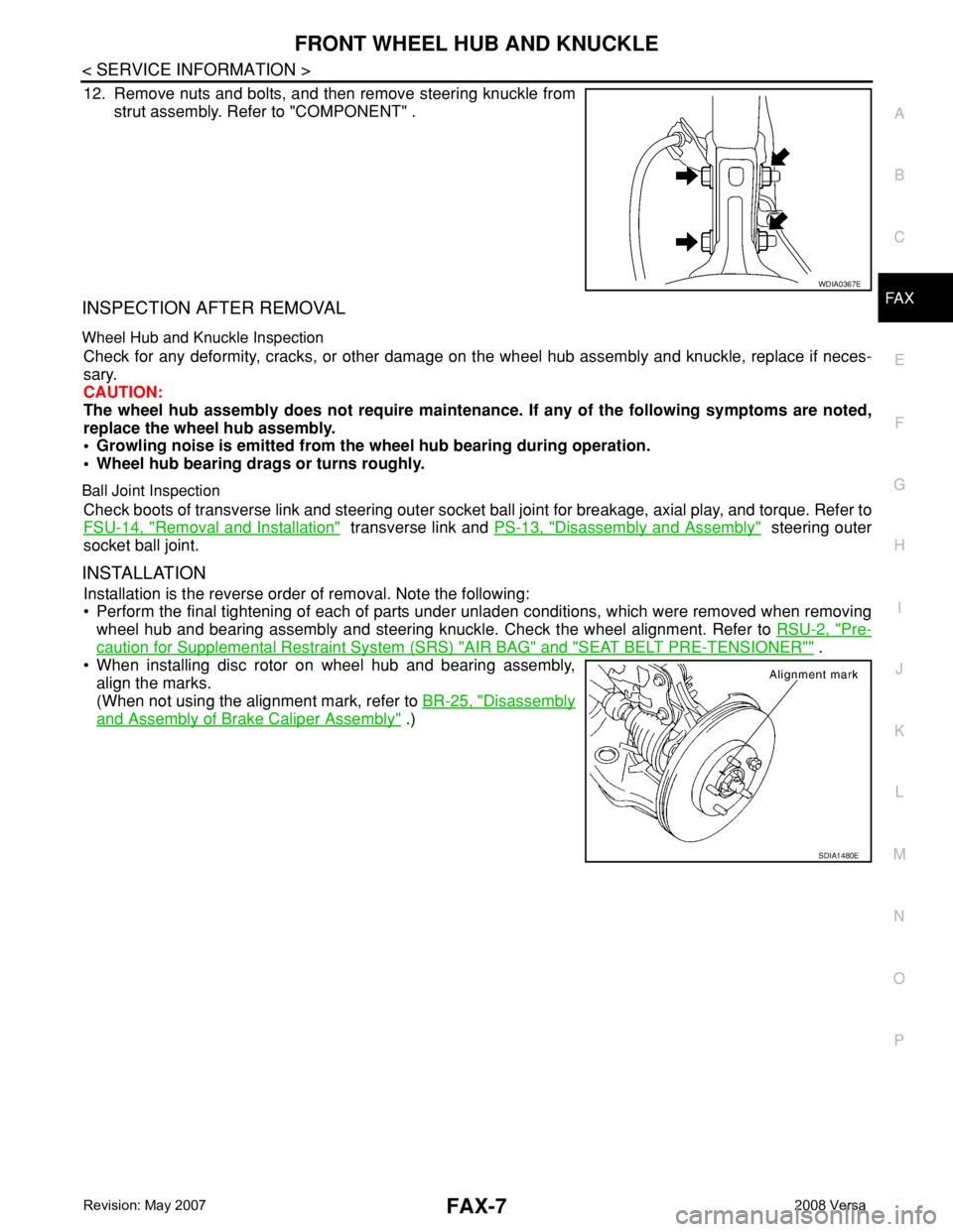
12. Remove nuts and bolts, and then remove steering knuckle from
strut assembly. Refer to "COMPONENT" .
INSPECTION AFTER REMOVAL
Wheel Hub and Knuckle Inspection
Check for any deformity, cracks, or other damage on the wheel hub assembly and knuckle, replace if neces-
sary.
CAUTION:
The wheel hub assembly does not require maintenance. If any of the following symptoms are noted,
replace the wheel hub assembly.
• Growling noise is emitted from the wheel hub bearing during operation.
• Wheel hub bearing drags or turns roughly.
Ball Joint Inspection
Check boots of transverse link and steering outer socket ball joint for breakage, axial play, and torque. Refer to
FSU-14, "
Removal and Installation" transverse link and PS-13, "Disassembly and Assembly" steering outer
socket ball joint.
INSTALLATION
Installation is the reverse order of removal. Note the following:
• Perform the final tightening of each of parts under unladen conditions, which were removed when removing
wheel hub and bearing assembly and steering knuckle. Check the wheel alignment. Refer to RSU-2, "
Pre-
caution for Supplemental Restraint System (SRS) "AIR BAG" and "SEAT BELT PRE-TENSIONER"" .
• When installing disc rotor on wheel hub and bearing assembly,
align the marks.
(When not using the alignment mark, refer to BR-25, "
Disassembly
and Assembly of Brake Caliper Assembly" .)
WDIA0367E
SDIA1480E
Page 1835 of 2771

FSU-1
SUSPENSION
C
D
F
G
H
I
J
K
L
M
SECTION FSU
A
B
FSU
N
O
PCONTENTS
FRONT SUSPENSION
SERVICE INFORMATION ............................2
PRECAUTIONS ...................................................2
Precaution for Supplemental Restraint System
(SRS) "AIR BAG" and "SEAT BELT PRE-TEN-
SIONER" ...................................................................
2
Precaution for Procedure without Cowl Top Cover ......2
Cautions ....................................................................2
PREPARATION ...................................................3
Special Service Tool .................................................3
Commercial Service Tool ..........................................4
NOISE, VIBRATION AND HARSHNESS
(NVH) TROUBLESHOOTING .............................
5
NVH Troubleshooting Chart ......................................5
FRONT SUSPENSION ASSEMBLY ...................6
On-Vehicle Inspection and Service ...........................6
Wheel Alignment Inspection .....................................6
Component ...............................................................9
Removal and Installation .........................................10
COIL SPRING AND STRUT ..............................11
Removal and Installation .........................................11
Disassembly and Assembly .....................................11
TRANSVERSE LINK .........................................14
Removal and Installation .........................................14
STABILIZER BAR .............................................15
Removal and Installation .........................................15
SERVICE DATA AND SPECIFICATIONS
(SDS) .................................................................
16
Wheel Alignment (Unladen*) ...................................16
Ball Joint ..................................................................16
Wheelarch Height (Unladen*) ..................................17
Page 1836 of 2771
FSU-2
< SERVICE INFORMATION >
PRECAUTIONS
SERVICE INFORMATION
PRECAUTIONS
Precaution for Supplemental Restraint System (SRS) "AIR BAG" and "SEAT BELT
PRE-TENSIONER"
INFOID:0000000001703715
The Supplemental Restraint System such as “AIR BAG” and “SEAT BELT PRE-TENSIONER”, used along
with a front seat belt, helps to reduce the risk or severity of injury to the driver and front passenger for certain
types of collision. This system includes seat belt switch inputs and dual stage front air bag modules. The SRS
system uses the seat belt switches to determine the front air bag deployment, and may only deploy one front
air bag, depending on the severity of a collision and whether the front occupants are belted or unbelted.
Information necessary to service the system safely is included in the SRS and SB section of this Service Man-
ual.
WARNING:
• To avoid rendering the SRS inoperative, which could increase the risk of personal injury or death in
the event of a collision which would result in air bag inflation, all maintenance must be performed by
an authorized NISSAN/INFINITI dealer.
• Improper maintenance, including incorrect removal and installation of the SRS, can lead to personal
injury caused by unintentional activation of the system. For removal of Spiral Cable and Air Bag
Module, see the SRS section.
• Do not use electrical test equipment on any circuit related to the SRS unless instructed to in this
Service Manual. SRS wiring harnesses can be identified by yellow and/or orange harnesses or har-
ness connectors.
Precaution for Procedure without Cowl Top CoverINFOID:0000000001703716
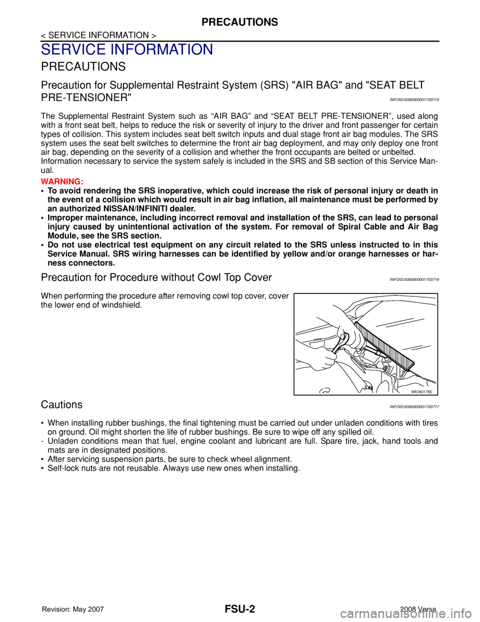
When performing the procedure after removing cowl top cover, cover
the lower end of windshield.
CautionsINFOID:0000000001703717
• When installing rubber bushings, the final tightening must be carried out under unladen conditions with tires
on ground. Oil might shorten the life of rubber bushings. Be sure to wipe off any spilled oil.
- Unladen conditions mean that fuel, engine coolant and lubricant are full. Spare tire, jack, hand tools and
mats are in designated positions.
• After servicing suspension parts, be sure to check wheel alignment.
• Self-lock nuts are not reusable. Always use new ones when installing.
WEIA0178E
Page 1837 of 2771
PREPARATION
FSU-3
< SERVICE INFORMATION >
C
D
F
G
H
I
J
K
L
MA
B
FSU
N
O
P
PREPARATION
Special Service ToolINFOID:0000000001703718
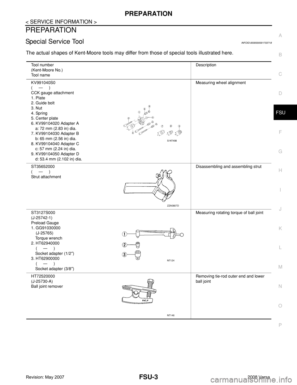
The actual shapes of Kent-Moore tools may differ from those of special tools illustrated here.
Tool number
(Kent-Moore No.)
Tool nameDescription
KV991040S0
(—)
CCK gauge attachment
1. Plate
2. Guide bolt
3. Nut
4. Spring
5. Center plate
6. KV99104020 Adapter A
a: 72 mm (2.83 in) dia.
7. KV99104030 Adapter B
b: 65 mm (2.56 in) dia.
8. KV99104040 Adapter C
c: 57 mm (2.24 in) dia.
9. KV99104050 Adapter D
d: 53.4 mm (2.102 in) dia.Measuring wheel alignment
ST35652000
(—)
Strut attachmentDisassembling and assembling strut
ST3127S000
(J-25742-1)
Preload Gauge
1. GG91030000
(J-25765)
Torque wrench
2. HT62940000
( — )
Socket adapter (1/2″)
3. HT62900000
( — )
Socket adapter (3/8″)Measuring rotating torque of ball joint
HT72520000
(J-25730-A)
Ball joint removerRemoving tie-rod outer end and lower
ball joint
S-NT498
ZZA0807D
NT124
NT146
Page 1838 of 2771
FSU-4
< SERVICE INFORMATION >
PREPARATION
Commercial Service Tool
INFOID:0000000001703719
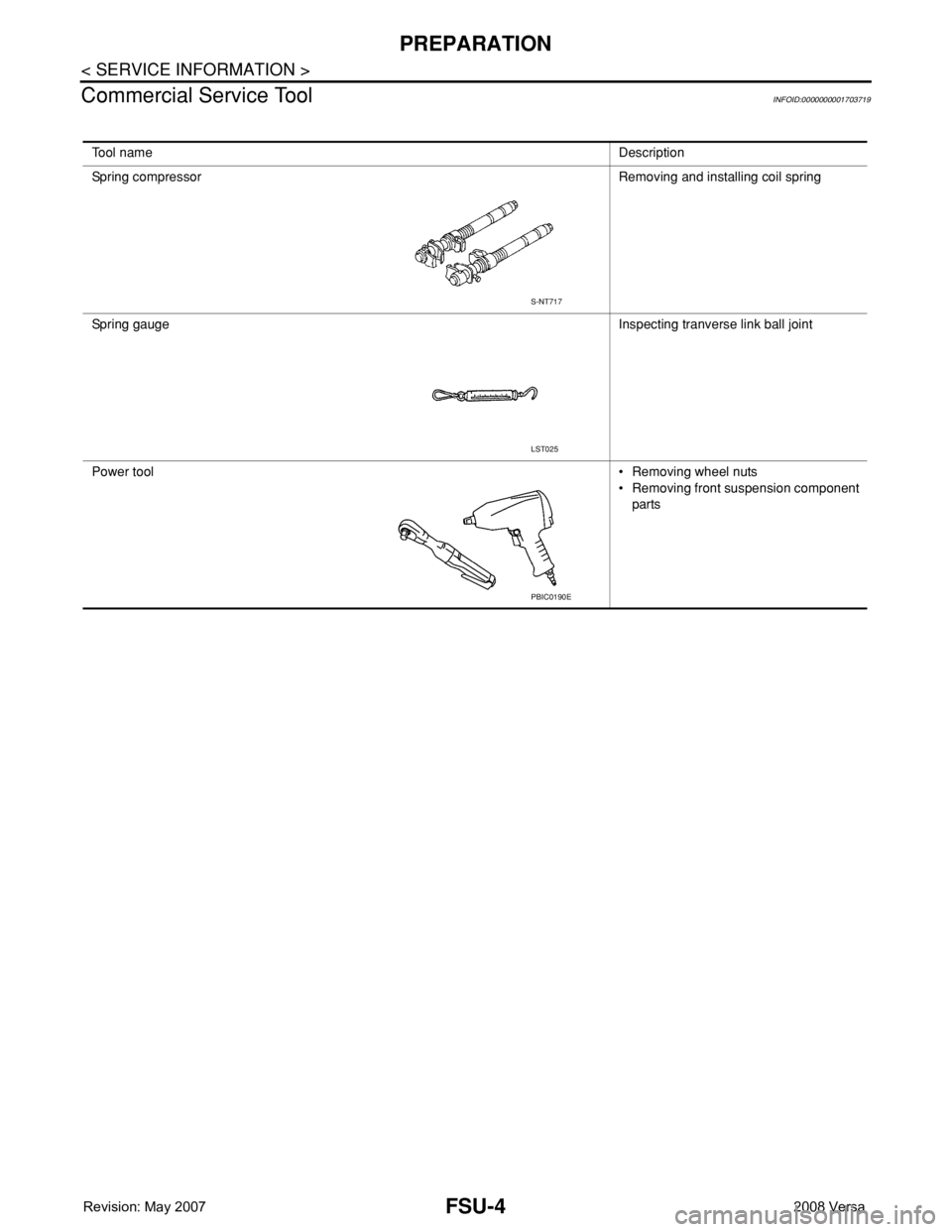
Tool nameDescription
Spring compressor Removing and installing coil spring
Spring gaugeInspecting tranverse link ball joint
Power tool• Removing wheel nuts
• Removing front suspension component
parts
S-NT717
LST025
PBIC0190E
Page 1839 of 2771
NOISE, VIBRATION AND HARSHNESS (NVH) TROUBLESHOOTING
FSU-5
< SERVICE INFORMATION >
C
D
F
G
H
I
J
K
L
MA
B
FSU
N
O
P
NOISE, VIBRATION AND HARSHNESS (NVH) TROUBLESHOOTING
NVH Troubleshooting ChartINFOID:0000000001703720
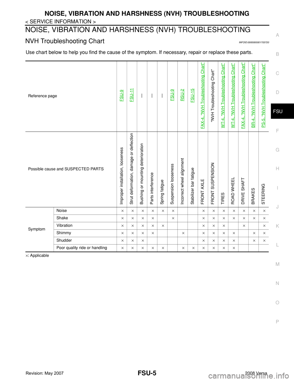
Use chart below to help you find the cause of the symptom. If necessary, repair or replace these parts.
×: ApplicableReference page
FSU-9 FSU-11
—
—
—
FSU-9 RSU-2FSU-15
FAX-4, "
NVH Troubleshooting Chart
"
"NVH Troubleshooting Chart"
WT-4, "
NVH Troubleshooting Chart
"
WT-4, "
NVH Troubleshooting Chart
"
FAX-4, "
NVH Troubleshooting Chart
"
BR-4, "
NVH Troubleshooting Chart
"
PS-5, "
NVH Troubleshooting Chart
"
Possible cause and SUSPECTED PARTS
Improper installation, looseness
Strut deformation, damage or deflection
Bushing or mounting deterioration
Parts interference
Spring fatigue
Suspension looseness
Incorrect wheel alignment
Stabilizer bar fatigue
FRONT AXLE
FRONT SUSPENSION
TIRES
ROAD WHEEL
DRIVE SHAFT
BRAKES
STEERING
SymptomNoise×××××× ×××××××
Shake×××× × ×××××××
Vibration××××× ××× × ×
Shimmy×××× × ×××× ××
Shudder××× ×××× ××
Poor quality ride or handling××××× ××××××
Page 1840 of 2771
FSU-6
< SERVICE INFORMATION >
FRONT SUSPENSION ASSEMBLY
FRONT SUSPENSION ASSEMBLY
On-Vehicle Inspection and ServiceINFOID:0000000001703721
Make sure the mounting conditions (looseness, back lash) of each component and component conditions
(wear, damage) are normal.
INSPECTION OF LOWER BALL JOINT END PLAY
1. Set front wheels in a straight-ahead position. Do not depress brake pedal.
2. Place an iron bar or similar tool between transverse link and steering knuckle.
3. Measure axial end play by prying it up and down.
CAUTION:
Be careful not to damage ball joint boot. Do not damage the installation position by applying
excessive force.
STRUT INSPECTION
Check for oil leakage, damage and replace as necessary.
Wheel Alignment InspectionINFOID:0000000001703722
PRELIMINARY INSPECTION
WARNING:
Always adjust the alignment with the vehicle on a flat surface.
NOTE:
If alignment is out of specification, inspect and replace any damaged or worn rear suspension parts before
making any adjustments.
1. Check and adjust the wheel alignment with the vehicle under unladen conditions. “Unladen conditions”
means that the fuel, coolant, and lubricant are full; and that the spare tire, jack, hand tools and mats are in
their designated positions.
2. Check the tires for incorrect air pressure and excessive wear.
3. Check the wheels for run out and damage. Refer to WT-5, "
Inspection" .
4. Check the wheel bearing axial end play. Refer to FA X - 5 , "
On-Vehicle Inspection and Service" .
5. Check the shock absorbers for leaks or damage.
6. Check each mounting point of the suspension components for any excessive looseness or damage.
7. Check each link, arm, and the suspension member for any damage.
8. Check the vehicle height. Refer to FSU-17, "
Wheelarch Height (Unladen*)" .
GENERAL INFORMATION AND RECOMMENDATIONS
1. A Four-Wheel Thrust Alignment should be performed.
• This type of alignment is recommended for any NISSAN vehicle.
• The four-wheel “thrust” process helps ensure that the vehicle is properly aligned and the steering wheel
is centered.
• The alignment machine itself should be capable of accepting any NISSAN vehicle.
• The alignment machine should be checked to ensure that it is level.
2. Make sure the alignment machine is properly calibrated.
• Your alignment machine should be regularly calibrated in order to give correct information.
• Check with the manufacturer of your specific alignment machine for their recommended Service/Cali-
bration Schedule.
THE ALIGNMENT PROCESS
IMPORTANT: Use only the alignment specifications listed in this Service Manual. Refer to FSU-16, "Wheel
Alignment (Unladen*)" .
1. When displaying the alignment settings, many alignment machines use “indicators”: (Green/red, plus or
minus, Go/No Go). Do NOT use these indicators.
• The alignment specifications programmed into your alignment machine that operate these indicators
may not be correct.Axial end play : 0 mm (0 in)