connector d2 NISSAN TIIDA 2008 Service Repair Manual
[x] Cancel search | Manufacturer: NISSAN, Model Year: 2008, Model line: TIIDA, Model: NISSAN TIIDA 2008Pages: 2771, PDF Size: 60.61 MB
Page 9 of 2771
ACC-2
< SERVICE INFORMATION >
PRECAUTIONS
SERVICE INFORMATION
PRECAUTIONS
Precaution for Supplemental Restraint System (SRS) "AIR BAG" and "SEAT BELT
PRE-TENSIONER"
INFOID:0000000001703109
The Supplemental Restraint System such as “AIR BAG” and “SEAT BELT PRE-TENSIONER”, used along
with a front seat belt, helps to reduce the risk or severity of injury to the driver and front passenger for certain
types of collision. This system includes seat belt switch inputs and dual stage front air bag modules. The SRS
system uses the seat belt switches to determine the front air bag deployment, and may only deploy one front
air bag, depending on the severity of a collision and whether the front occupants are belted or unbelted.
Information necessary to service the system safely is included in the SR and SB section of this Service Man-
ual.
WARNING:
• To avoid rendering the SRS inoperative, which could increase the risk of personal injury or death in
the event of a collision which would result in air bag inflation, all maintenance must be performed by
an authorized NISSAN/INFINITI dealer.
• Improper maintenance, including incorrect removal and installation of the SRS, can lead to personal
injury caused by unintentional activation of the system. For removal of Spiral Cable and Air Bag
Module, see the SR section.
• Do not use electrical test equipment on any circuit related to the SRS unless instructed to in this
Service Manual. SRS wiring harnesses can be identified by yellow and/or orange harnesses or har-
ness connectors.
Page 10 of 2771
ACCELERATOR CONTROL SYSTEM
ACC-3
< SERVICE INFORMATION >
C
D
E
F
G
H
I
J
K
L
MA
ACC
N
P O
ACCELERATOR CONTROL SYSTEM
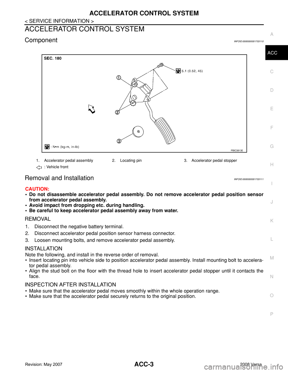
ComponentINFOID:0000000001703110
Removal and InstallationINFOID:0000000001703111
CAUTION:
• Do not disassemble accelerator pedal assembly. Do not remove accelerator pedal position sensor
from accelerator pedal assembly.
• Avoid impact from dropping etc. during handling.
• Be careful to keep accelerator pedal assembly away from water.
REMOVAL
1. Disconnect the negative battery terminal.
2. Disconnect accelerator pedal position sensor harness connector.
3. Loosen mounting bolts, and remove accelerator pedal assembly.
INSTALLATION
Note the following, and install in the reverse order of removal.
• Insert locating pin into vehicle side to position accelerator pedal assembly. Install mounting bolt to accelera-
tor pedal assembly.
• Align the stud bolt on the floor with the thread hole to insert accelerator pedal stopper until it contacts the
face.
INSPECTION AFTER INSTALLATION
• Make sure that the accelerator pedal moves smoothly within the whole operation range.
• Make sure that the accelerator pedal securely returns to the original position.
1. Accelerator pedal assembly 2. Locating pin 3. Accelerator pedal stopper
: Vehicle front
PBIC3813E
Page 19 of 2771
PRECAUTIONS
AT-7
< SERVICE INFORMATION >
D
E
F
G
H
I
J
K
L
MA
B
AT
N
O
P
PRECAUTIONS
Precaution for Supplemental Restraint System (SRS) "AIR BAG" and "SEAT BELT
PRE-TENSIONER"
INFOID:0000000001703151
The Supplemental Restraint System such as “AIR BAG” and “SEAT BELT PRE-TENSIONER”, used along
with a front seat belt, helps to reduce the risk or severity of injury to the driver and front passenger for certain
types of collision. This system includes seat belt switch inputs and dual stage front air bag modules. The SRS
system uses the seat belt switches to determine the front air bag deployment, and may only deploy one front
air bag, depending on the severity of a collision and whether the front occupants are belted or unbelted.
Information necessary to service the system safely is included in the SRS and SB section of this Service Man-
ual.
WARNING:
• To avoid rendering the SRS inoperative, which could increase the risk of personal injury or death in
the event of a collision which would result in air bag inflation, all maintenance must be performed by
an authorized NISSAN/INFINITI dealer.
• Improper maintenance, including incorrect removal and installation of the SRS, can lead to personal
injury caused by unintentional activation of the system. For removal of Spiral Cable and Air Bag
Module, see the SRS section.
• Do not use electrical test equipment on any circuit related to the SRS unless instructed to in this
Service Manual. SRS wiring harnesses can be identified by yellow and/or orange harnesses or har-
ness connectors.
Precaution Necessary for Steering Wheel Rotation After Battery Disconnect
INFOID:0000000001703152
NOTE:
• This Procedure is applied only to models with Intelligent Key system and NVIS/IVIS (NISSAN/INFINITI
VEHICLE IMMOBILIZER SYSTEM - NATS).
• Remove and install all control units after disconnecting both battery cables with the ignition knob in the
″LOCK″ position.
• Always use CONSULT-III to perform self-diagnosis as a part of each function inspection after finishing work.
If DTC is detected, perform trouble diagnosis according to self-diagnostic results.
For models equipped with the Intelligent Key system and NVIS/IVIS, an electrically controlled steering lock
mechanism is adopted on the key cylinder.
For this reason, if the battery is disconnected or if the battery is discharged, the steering wheel will lock and
steering wheel rotation will become impossible.
If steering wheel rotation is required when battery power is interrupted, follow the procedure below before
starting the repair operation.
OPERATION PROCEDURE
1. Connect both battery cables.
NOTE:
Supply power using jumper cables if battery is discharged.
2. Use the Intelligent Key or mechanical key to turn the ignition switch to the ″ACC″ position. At this time, the
steering lock will be released.
3. Disconnect both battery cables. The steering lock will remain released and the steering wheel can be
rotated.
4. Perform the necessary repair operation.
5. When the repair work is completed, return the ignition switch to the ″LOCK″ position before connecting
the battery cables. (At this time, the steering lock mechanism will engage.)
6. Perform a self-diagnosis check of all control units using CONSULT-III.
Precaution for On Board Diagnosis (OBD) System of A/T and EngineINFOID:0000000001703153
The ECM has an on board diagnostic system. It will light up the malfunction indicator lamp (MIL) to warn the
driver of a malfunction causing emission deterioration.
CAUTION:
Page 20 of 2771
AT-8
< SERVICE INFORMATION >
PRECAUTIONS
• Be sure to turn the ignition switch OFF and disconnect battery negative cable from battery negative
terminal before any repair or inspection work. The open/short circuit of related switches, sensors,
solenoid valves, etc. will cause the MIL to light up.
• Be sure to connect and lock the connectors securely after work. A loose (unlocked) connector will
cause the MIL to light up due to an open circuit. (Be sure the connectors are free from water, grease,
dirt, bent terminals, etc.)
• Be sure to route and secure the harnesses properly after work. Interference of the harness with a
bracket, etc. may cause the MIL to light up due to a short circuit.
• Be sure to erase the unnecessary malfunction information (repairs completed) from the TCM and
ECM before returning the vehicle to the customer.
PrecautionINFOID:0000000001703154
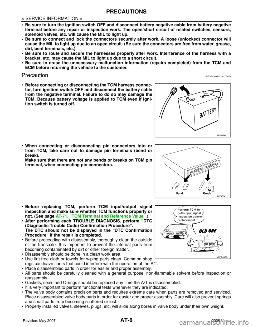
•Before connecting or disconnecting the TCM harness connec-
tor, turn ignition switch OFF and disconnect the battery cable
from the negative terminal. Failure to do so may damage the
TCM. Because battery voltage is applied to TCM even if igni-
tion switch is turned off.
•When connecting or disconnecting pin connectors into or
from TCM, take care not to damage pin terminals (bend or
break).
Make sure that there are not any bends or breaks on TCM pin
terminal, when connecting pin connectors.
•Before replacing TCM, perform TCM input/output signal
inspection and make sure whether TCM functions properly or
not. (See page AT-71, "
TCM Terminal and Reference Value".)
•After performing each TROUBLE DIAGNOSIS, perform “DTC
(Diagnostic Trouble Code) Confirmation Procedure”.
The DTC should not be displayed in the “DTC Confirmation
Procedure” if the repair is completed.
• Before proceeding with disassembly, thoroughly clean the outside
of the transaxle. It is important to prevent the internal parts from
becoming contaminated by dirt or other foreign matter.
• Disassembly should be done in a clean work area.
• Use lint-free cloth or towels for wiping parts clean. Common shop
rags can leave fibers that could interfere with the operation of the A/T.
• Place disassembled parts in order for easier and proper assembly.
• All parts should be carefully cleaned with a general purpose, non-flammable solvent before inspection or
reassembly.
• Gaskets, seals and O-rings should be replaced any time the A/T is disassembled.
• It is very important to perform functional tests whenever they are indicated.
• The valve body contains precision parts and requires extreme care when parts are removed and serviced.
Place disassembled valve body parts in order for easier and proper assembly. Care will also prevent springs
and small parts from becoming scattered or lost.
• Properly installed valves, sleeves, plugs, etc. will slide along bores in valve body under their own weight.
SEF289H
AAT470A
MEF040DA
Page 21 of 2771
PRECAUTIONS
AT-9
< SERVICE INFORMATION >
D
E
F
G
H
I
J
K
L
MA
B
AT
N
O
P
• Before assembly, apply a coat of recommended ATF to all parts. Apply petroleum jelly to protect O-rings and
seals, or hold bearings and washers in place during assembly. Do not use grease.
• Extreme care should be taken to avoid damage to O-rings, seals and gaskets when assembling.
• Clean or replace ATF cooler if excessive foreign material is found in oil pan or clogging strainer. Refer to
Refer to .
• After overhaul, refill the A/T with new ATF.
• When the A/T drain plug is removed, only some of the fluid is drained. Old A/T fluid will remain in torque con-
verter and ATF cooling system.
Always follow the procedures under “Changing A/T Fluid” in the AT section when changing A/T fluid. Refer to
MA-22, "
Changing A/T Fluid", MA-22, "Checking A/T Fluid".
Service Notice or PrecautionINFOID:0000000001703155
ATF COOLER SERVICE
If A/T fluid contains frictional material (clutches, bands, etc.), or if an A/T is repaired, overhauled, or replaced,
inspect and clean the A/T oil cooler mounted in the radiator or replace the radiator. Flush cooler lines using
cleaning solvent and compressed air after repair. Check Service Bulletins for latest A/T oil cooler cleaning pro-
cedure. For radiator replacement, refer to Refer to CO-11
.
TORQUE CONVERTER SERVICE
The torque converter should be replaced under any of the following conditions:
• External leaks in the hub weld area.
• Converter hub is scored or damaged.
• Converter pilot is broken, damaged or fits poorly into crankshaft.
• Steel particles are found after flushing the cooler and cooler lines.
• Pump is damaged or steel particles are found in the converter.
• Vehicle has TCC shudder and/or no TCC apply. Replace only after all hydraulic and electrical diagnoses
have been made. (Converter clutch material may be glazed.)
• Converter is contaminated with engine coolant containing antifreeze.
• Internal malfunction of stator roller clutch.
• Heavy clutch debris due to overheating (blue converter).
• Steel particles or clutch lining material found in fluid filter or on magnet when no internal parts in unit are
worn or damaged — indicates that lining material came from converter.
The torque converter should not be replaced if:
• The fluid has an odor, is discolored, and there is no evidence of metal or clutch facing particles.
• The threads in one or more of the converter bolt holes are damaged.
• A/T malfunction did not display evidence of damaged or worn internal parts, steel particles or clutch plate lin-
ing material in unit and inside the fluid filter.
• Vehicle has been exposed to high mileage (only). The exception may be where the torque converter clutch
dampener plate lining has seen excess wear by vehicles operated in heavy and/or constant traffic, such as
taxi, delivery or police use.
OBD-II SELF-DIAGNOSIS
• A/T self-diagnosis is performed by the TCM in combination with the ECM. The results can be read through
the blinking pattern of the OD OFF indicator lamp or the malfunction indicator lamp (MIL). Refer to the table
on AT-78, "
Diagnosis Procedure without CONSULT-III" for the indicator used to display each self-diagnostic
result.
• The self-diagnostic results indicated by the MIL are automatically stored in both the ECM and TCM memo-
ries.
Always perform the procedure “HOW TO ERASE DTC” on AT-36, "
OBD-II Diagnostic Trouble Code
(DTC)" to complete the repair and avoid unnecessary blinking of the MIL.
• The following self-diagnostic items can be detected using ECM self-diagnostic results mode* only when the
OD OFF indicator lamp does not indicate any malfunctions.
-PNP switch
- A/T 1st, 2nd, 3rd, or 4th gear function
*: For details of OBD-II, refer to AT- 3 6
.
•Certain systems and components, especially those related to OBD, may use a new style slide-lock-
ing type harness connector.
For description and how to disconnect, refer to PG-65
.
Page 58 of 2771
AT-46
< SERVICE INFORMATION >
TROUBLE DIAGNOSIS
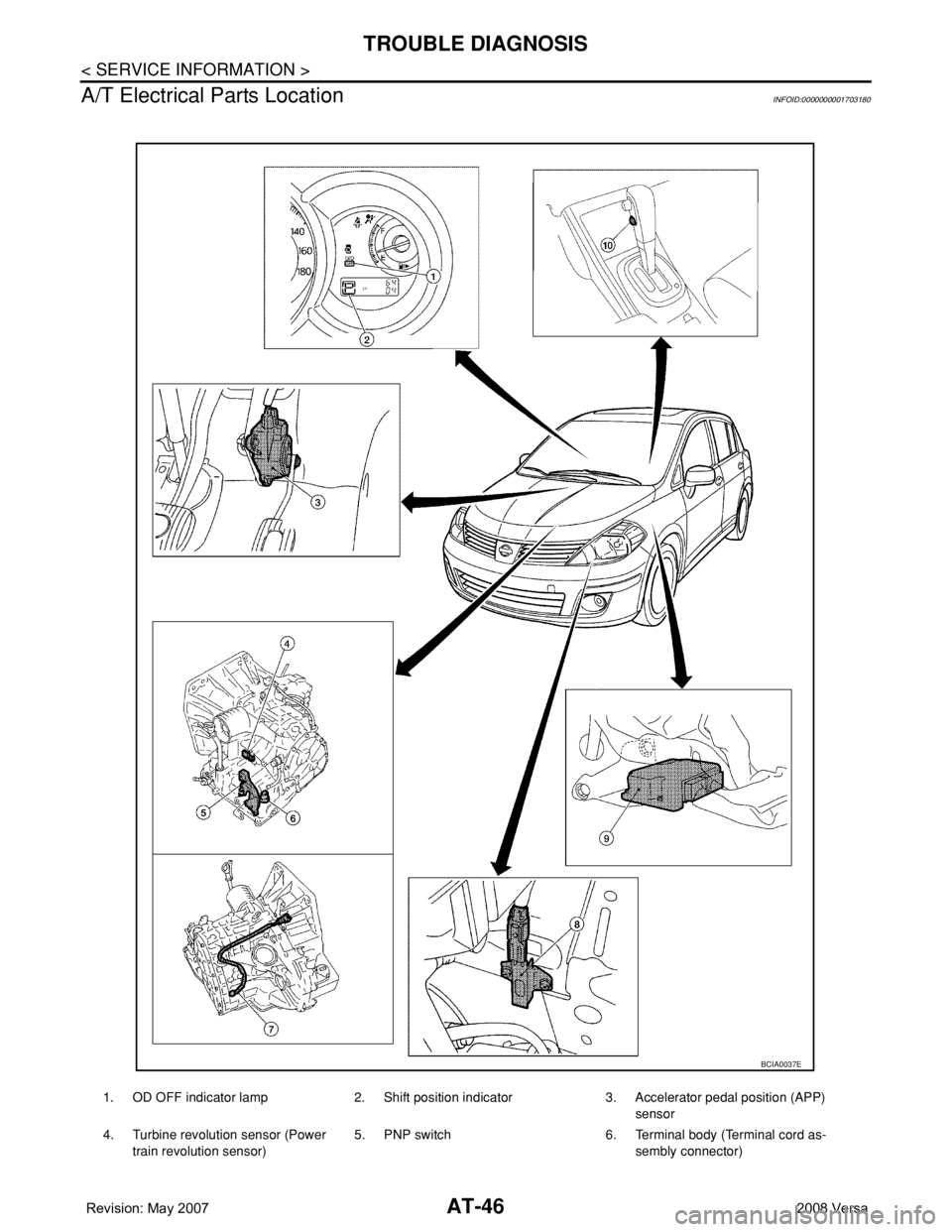
A/T Electrical Parts Location
INFOID:0000000001703180
1. OD OFF indicator lamp 2. Shift position indicator 3. Accelerator pedal position (APP)
sensor
4. Turbine revolution sensor (Power
train revolution sensor)5. PNP switch 6. Terminal body (Terminal cord as-
sembly connector)
BCIA0037E
Page 83 of 2771
TROUBLE DIAGNOSIS
AT-71
< SERVICE INFORMATION >
D
E
F
G
H
I
J
K
L
MA
B
AT
N
O
P
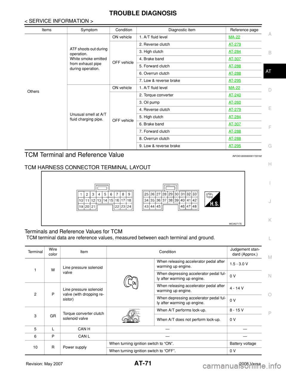
TCM Terminal and Reference ValueINFOID:0000000001703192
TCM HARNESS CONNECTOR TERMINAL LAYOUT
Terminals and Reference Values for TCM
TCM terminal data are reference values, measured between each terminal and ground.
OthersATF shoots out during
operation.
White smoke emitted
from exhaust pipe
during operation.ON vehicle 1. A/T fluid levelMA-22
OFF vehicle2. Reverse clutchAT- 2 7 9
3. High clutchAT- 2 8 4
4. Brake bandAT- 3 0 7
5. Forward clutchAT- 2 8 8
6. Overrun clutchAT- 2 8 8
7. Low & reverse brakeAT- 2 9 5
Unusual smell at A/T
fluid charging pipe.ON vehicle 1. A/T fluid levelMA-22
OFF vehicle2. Torque converterAT- 2 4 0
3. Oil pumpAT- 2 6 0
4. Reverse clutchAT- 2 7 9
5. High clutchAT- 2 8 4
6. Brake bandAT- 3 0 7
7. Forward clutchAT- 2 8 8
8. Overrun clutchAT- 2 8 8
9. Low & reverse brakeAT- 2 9 5
Items Symptom Condition Diagnostic item Reference page
WCIA0717E
Te r m i n a lWire
colorItem ConditionJudgement stan-
dard (Approx.)
1WLine pressure solenoid
valveWhen releasing accelerator pedal after
warming up engine.1.5 - 3.0 V
When depressing accelerator pedal ful-
ly after warming up engine.0 V
2PLine pressure solenoid
valve (with dropping re-
sistor)When releasing accelerator pedal after
warming up engine.4 - 14 V
When depressing accelerator pedal ful-
ly after warming up engine.0 V
3GRTorque converter clutch
solenoid valveWhen A/T performs lock-up. 8 - 15 V
When A/T does not perform lock-up. 0 V
5 L CAN H — —
6 P CAN L — —
10 R Power supplyWhen turning ignition switch to “ON”. Battery voltage
When turning ignition switch to “OFF”. 0 V
Page 85 of 2771
TROUBLE DIAGNOSIS
AT-73
< SERVICE INFORMATION >
D
E
F
G
H
I
J
K
L
MA
B
AT
N
O
P
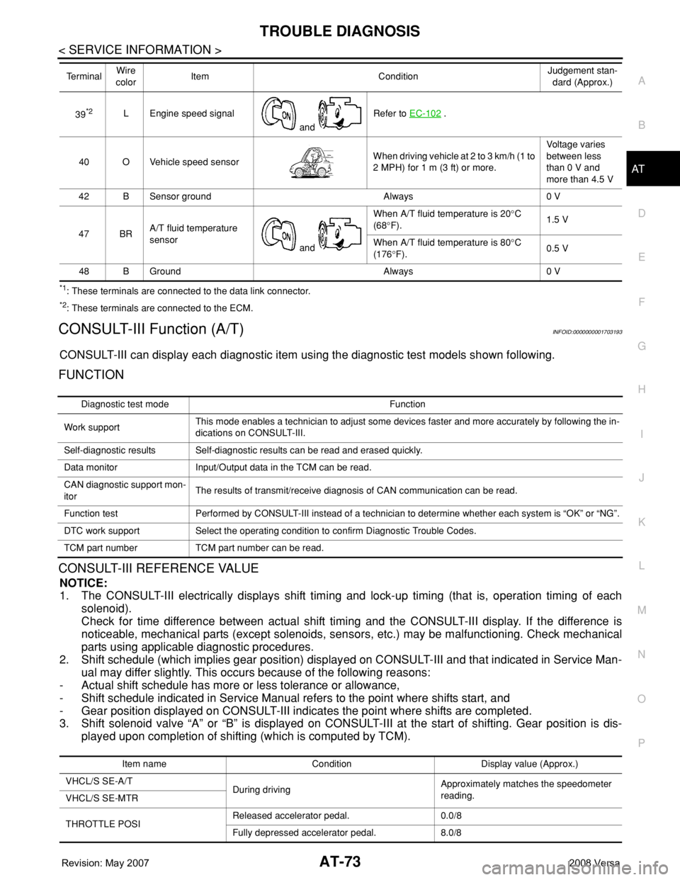
*1: These terminals are connected to the data link connector.
*2: These terminals are connected to the ECM.
CONSULT-III Function (A/T)INFOID:0000000001703193
CONSULT-III can display each diagnostic item using the diagnostic test models shown following.
FUNCTION
CONSULT-III REFERENCE VALUE
NOTICE:
1. The CONSULT-III electrically displays shift timing and lock-up timing (that is, operation timing of each
solenoid).
Check for time difference between actual shift timing and the CONSULT-III display. If the difference is
noticeable, mechanical parts (except solenoids, sensors, etc.) may be malfunctioning. Check mechanical
parts using applicable diagnostic procedures.
2. Shift schedule (which implies gear position) displayed on CONSULT-III and that indicated in Service Man-
ual may differ slightly. This occurs because of the following reasons:
- Actual shift schedule has more or less tolerance or allowance,
- Shift schedule indicated in Service Manual refers to the point where shifts start, and
- Gear position displayed on CONSULT-III indicates the point where shifts are completed.
3. Shift solenoid valve “A” or “B” is displayed on CONSULT-III at the start of shifting. Gear position is dis-
played upon completion of shifting (which is computed by TCM).
39*2L Engine speed signal
and Refer to EC-102 .
40 O Vehicle speed sensorWhen driving vehicle at 2 to 3 km/h (1 to
2 MPH) for 1 m (3 ft) or more.Voltage varies
between less
than 0 V and
more than 4.5 V
42 B Sensor ground Always 0 V
47 BRA/T fluid temperature
sensor
and When A/T fluid temperature is 20°C
(68°F).1.5 V
When A/T fluid temperature is 80°C
(176°F).0.5 V
48 B Ground Always 0 V Te r m i n a lWire
colorItem ConditionJudgement stan-
dard (Approx.)
Diagnostic test mode Function
Work supportThis mode enables a technician to adjust some devices faster and more accurately by following the in-
dications on CONSULT-III.
Self-diagnostic results Self-diagnostic results can be read and erased quickly.
Data monitor Input/Output data in the TCM can be read.
CAN diagnostic support mon-
itorThe results of transmit/receive diagnosis of CAN communication can be read.
Function test Performed by CONSULT-III instead of a technician to determine whether each system is “OK” or “NG”.
DTC work support Select the operating condition to confirm Diagnostic Trouble Codes.
TCM part number TCM part number can be read.
Item name Condition Display value (Approx.)
VHCL/S SE-A/T
During drivingApproximately matches the speedometer
reading.
VHCL/S SE-MTR
THROTTLE POSIReleased accelerator pedal. 0.0/8
Fully depressed accelerator pedal. 8.0/8
Page 95 of 2771
DTC U1000 CAN COMMUNICATION LINE
AT-83
< SERVICE INFORMATION >
D
E
F
G
H
I
J
K
L
MA
B
AT
N
O
P
DTC U1000 CAN COMMUNICATION LINE
DescriptionINFOID:0000000001703195
CAN (Controller Area Network) is a serial communication line for real time application. It is an on-vehicle mul-
tiplex communication line with high data communication speed and excellent malfunction detection ability.
Many electronic control units are equipped onto a vehicle, and each control unit shares information and links
with other control units during operation (not independent). In CAN communication, control units are con-
nected with 2 communication lines (CAN H line, CAN L line) allowing a high rate of information transmission
with less wiring. Each control unit transmits/receives data but selectively reads required data only.
On Board Diagnosis LogicINFOID:0000000001703196
• This is an OBD-II self-diagnostic item.
• Diagnostic trouble code “U1000 CAN COMM CIRCUIT” with CONSULT-III or 12th judgement flicker without
CONSULT-III is detected when TCM cannot communicate to other control units.
Possible CauseINFOID:0000000001703197
Harness or connector
(CAN communication line is open or shorted.)
DTC Confirmation ProcedureINFOID:0000000001703198
CAUTION:
If performing this “DTC Confirmation Procedure” again, always turn ignition switch OFF and wait at
least 10 seconds before continuing.
After the repair, perform the following procedure to confirm the malfunction is eliminated.
WITH CONSULT-III
1. Turn ignition switch ON.
2. Select “DATA MONITOR” mode for “A/T” with CONSULT-III.
3. Touch “START”.
4. Wait at least 6 seconds or start engine and wait for at least 6 seconds.
5. If DTC is detected, go to AT-85, "
Diagnosis Procedure".
WITH GST
Follow the procedure “WITH CONSULT-III”.
WITHOUT CONSULT-III
1. Turn ignition switch ON.
2. Wait at least 6 seconds or start engine and wait at least 6 seconds.
3. Perform self-diagnosis. Refer to AT-78, "
Diagnosis Procedure without CONSULT-III".
4. If DTC is detected, go to AT-85, "
Diagnosis Procedure".
Page 98 of 2771
AT-86
< SERVICE INFORMATION >
DTC P0705 PARK/NEUTRAL POSITION (PNP) SWITCH
DTC P0705 PARK/NEUTRAL POSITION (PNP) SWITCH
DescriptionINFOID:0000000001703201
• The PNP switch assembly includes a transaxle range switch.
• The transaxle range switch detects the selector lever position and sends a signal to the TCM.
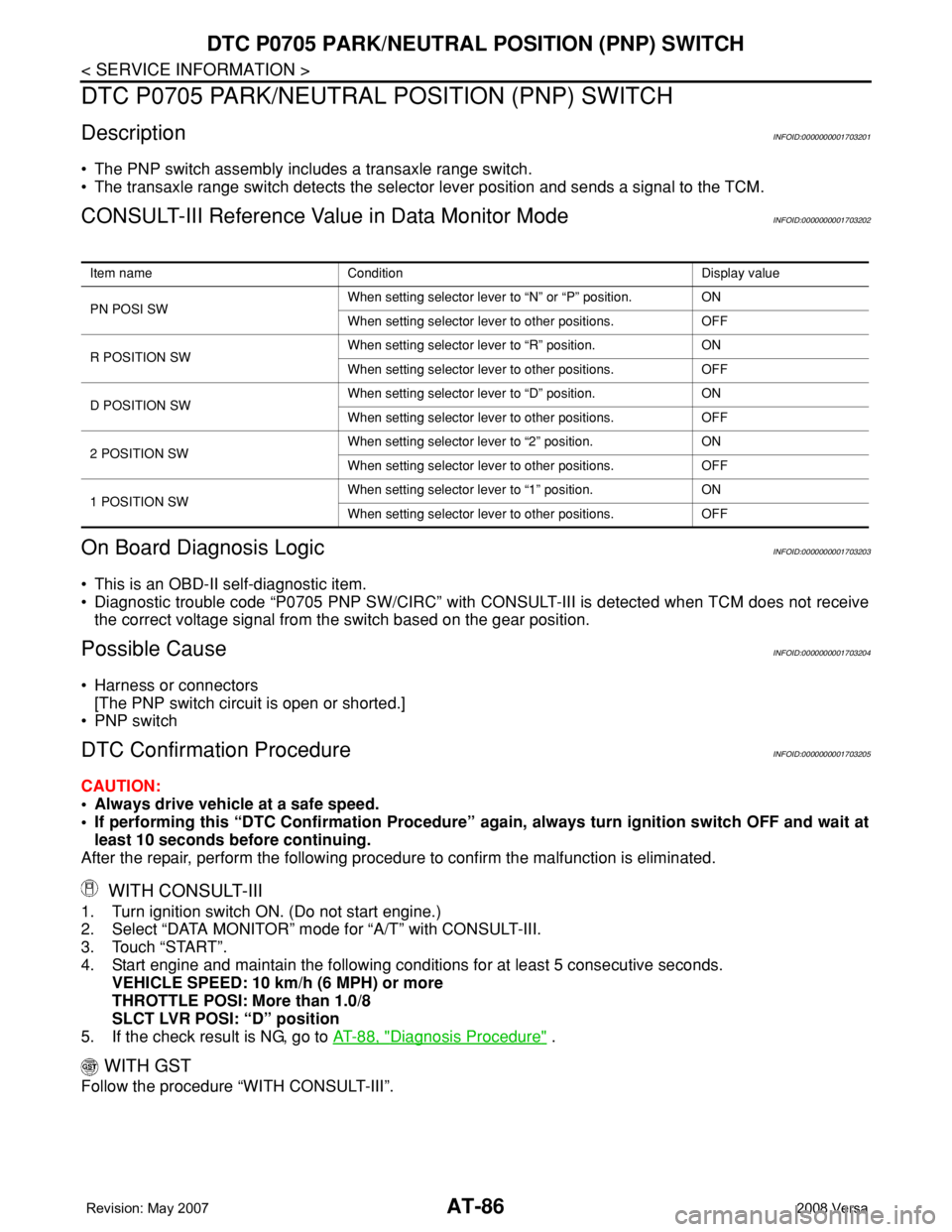
CONSULT-III Reference Value in Data Monitor ModeINFOID:0000000001703202
On Board Diagnosis LogicINFOID:0000000001703203
• This is an OBD-II self-diagnostic item.
• Diagnostic trouble code “P0705 PNP SW/CIRC” with CONSULT-III is detected when TCM does not receive
the correct voltage signal from the switch based on the gear position.
Possible CauseINFOID:0000000001703204
• Harness or connectors
[The PNP switch circuit is open or shorted.]
• PNP switch
DTC Confirmation ProcedureINFOID:0000000001703205
CAUTION:
• Always drive vehicle at a safe speed.
• If performing this “DTC Confirmation Procedure” again, always turn ignition switch OFF and wait at
least 10 seconds before continuing.
After the repair, perform the following procedure to confirm the malfunction is eliminated.
WITH CONSULT-III
1. Turn ignition switch ON. (Do not start engine.)
2. Select “DATA MONITOR” mode for “A/T” with CONSULT-III.
3. Touch “START”.
4. Start engine and maintain the following conditions for at least 5 consecutive seconds.
VEHICLE SPEED: 10 km/h (6 MPH) or more
THROTTLE POSI: More than 1.0/8
SLCT LVR POSI: “D” position
5. If the check result is NG, go to AT-88, "
Diagnosis Procedure" .
WITH GST
Follow the procedure “WITH CONSULT-III”.
Item name Condition Display value
PN POSI SWWhen setting selector lever to “N” or “P” position. ON
When setting selector lever to other positions. OFF
R POSITION SWWhen setting selector lever to “R” position. ON
When setting selector lever to other positions. OFF
D POSITION SWWhen setting selector lever to “D” position. ON
When setting selector lever to other positions. OFF
2 POSITION SWWhen setting selector lever to “2” position. ON
When setting selector lever to other positions. OFF
1 POSITION SWWhen setting selector lever to “1” position. ON
When setting selector lever to other positions. OFF