exhaust NISSAN TIIDA 2008 Service Repair Manual
[x] Cancel search | Manufacturer: NISSAN, Model Year: 2008, Model line: TIIDA, Model: NISSAN TIIDA 2008Pages: 2771, PDF Size: 60.61 MB
Page 1 of 2771
-1
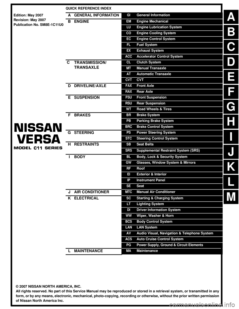
QUICK REFERENCE INDEX
AGENERAL INFORMATIONGIGeneral Information
BENGINEEMEngine Mechanical
LUEngine Lubrication System
COEngine Cooling System
ECEngine Control System
FLFuel System
EXExhaust System
ACCAccelerator Control System
CTRANSMISSION/
TRANSAXLECLClutch System
MTManual Transaxle
ATAutomatic Transaxle
CVTCVT
DDRIVELINE/AXLEFAXFront Axle
RAXRear Axle
ESUSPENSIONFSUFront Suspension
RSURear Suspension
WTRoad Wheels & Tires
FBRAKESBRBrake System
PBParking Brake System
BRCBrake Control System
GSTEERINGPSPower Steering System
STCSteering Control System
HRESTRAINTSSBSeat Belts
SRSSupplemental Restraint System (SRS)
IBODYBLBody, Lock & Security System
GWGlasses, Window System & Mirrors
RFRoof
EIExterior & Interior
IPInstrument Panel
SESeat
JAIR CONDITIONERMTCManual Air Conditioner
KELECTRICALSCStarting & Charging System
LTLighting System
DIDriver Information System
WWWiper, Washer & Horn
BCSBody Control System
LANLAN System
AVAudio Visual, Navigation & Telephone System
ACSAuto Cruise Control System
PGPower Supply, Ground & Circuit Elements
LMAINTENANCEMAMaintenance
Edition: May 2007
Revision: May 2007
Publication No. SM8E-1C11U0
B
D
© 2007 NISSAN NORTH AMERICA, INC.
All rights reserved. No part of this Service Manual may be reproduced or stored in a retrieval system, or transmitted in any
form, or by any means, electronic, mechanical, photo-copying, recording or otherwise, without the prior written permission
of Nissan North America Inc.
A
C
E
F
G
H
I
J
K
L
M
Page 83 of 2771
TROUBLE DIAGNOSIS
AT-71
< SERVICE INFORMATION >
D
E
F
G
H
I
J
K
L
MA
B
AT
N
O
P
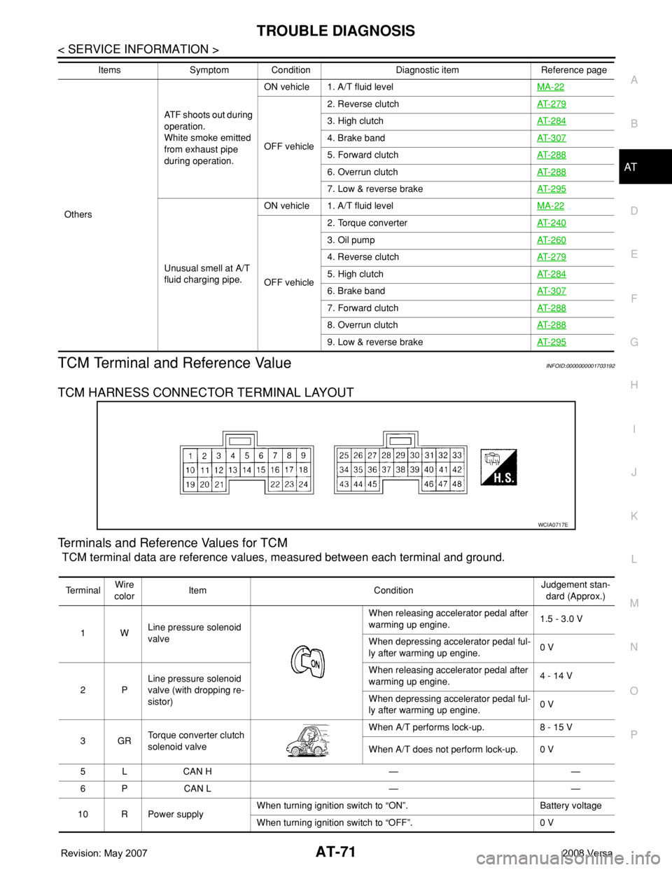
TCM Terminal and Reference ValueINFOID:0000000001703192
TCM HARNESS CONNECTOR TERMINAL LAYOUT
Terminals and Reference Values for TCM
TCM terminal data are reference values, measured between each terminal and ground.
OthersATF shoots out during
operation.
White smoke emitted
from exhaust pipe
during operation.ON vehicle 1. A/T fluid levelMA-22
OFF vehicle2. Reverse clutchAT- 2 7 9
3. High clutchAT- 2 8 4
4. Brake bandAT- 3 0 7
5. Forward clutchAT- 2 8 8
6. Overrun clutchAT- 2 8 8
7. Low & reverse brakeAT- 2 9 5
Unusual smell at A/T
fluid charging pipe.ON vehicle 1. A/T fluid levelMA-22
OFF vehicle2. Torque converterAT- 2 4 0
3. Oil pumpAT- 2 6 0
4. Reverse clutchAT- 2 7 9
5. High clutchAT- 2 8 4
6. Brake bandAT- 3 0 7
7. Forward clutchAT- 2 8 8
8. Overrun clutchAT- 2 8 8
9. Low & reverse brakeAT- 2 9 5
Items Symptom Condition Diagnostic item Reference page
WCIA0717E
Te r m i n a lWire
colorItem ConditionJudgement stan-
dard (Approx.)
1WLine pressure solenoid
valveWhen releasing accelerator pedal after
warming up engine.1.5 - 3.0 V
When depressing accelerator pedal ful-
ly after warming up engine.0 V
2PLine pressure solenoid
valve (with dropping re-
sistor)When releasing accelerator pedal after
warming up engine.4 - 14 V
When depressing accelerator pedal ful-
ly after warming up engine.0 V
3GRTorque converter clutch
solenoid valveWhen A/T performs lock-up. 8 - 15 V
When A/T does not perform lock-up. 0 V
5 L CAN H — —
6 P CAN L — —
10 R Power supplyWhen turning ignition switch to “ON”. Battery voltage
When turning ignition switch to “OFF”. 0 V
Page 216 of 2771
AT-204
< SERVICE INFORMATION >
SHIFT CONTROL SYSTEM
REMOVAL
CAUTION:
Make sure that parking brake is applied before removal/installation.
1. Place the selector lever in the “N” position.
2. Remove the center console assembly. Refer to IP-10
.
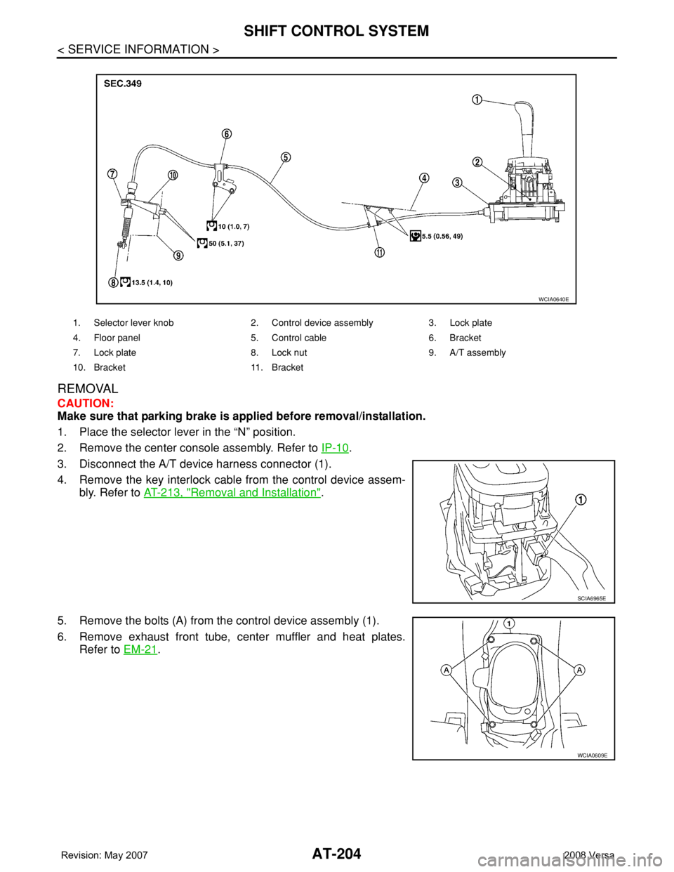
3. Disconnect the A/T device harness connector (1).
4. Remove the key interlock cable from the control device assem-
bly. Refer to AT-213, "
Removal and Installation".
5. Remove the bolts (A) from the control device assembly (1).
6. Remove exhaust front tube, center muffler and heat plates.
Refer to EM-21
.
1. Selector lever knob 2. Control device assembly 3. Lock plate
4. Floor panel 5. Control cable 6. Bracket
7. Lock plate 8. Lock nut 9. A/T assembly
10. Bracket 11. Bracket
WCIA0640E
SCIA6965E
WCIA0609E
Page 669 of 2771
BODY REPAIR
BL-235
< SERVICE INFORMATION >
C
D
E
F
G
H
J
K
L
MA
B
BL
N
O
P
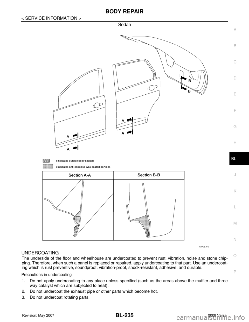
Sedan
UNDERCOATING
The underside of the floor and wheelhouse are undercoated to prevent rust, vibration, noise and stone chip-
ping. Therefore, when such a panel is replaced or repaired, apply undercoating to that part. Use an undercoat-
ing which is rust preventive, soundproof, vibration-proof, shock-resistant, adhesive, and durable.
Precautions in undercoating
1. Do not apply undercoating to any place unless specified (such as the areas above the muffler and three
way catalyst which are subjected to heat).
2. Do not undercoat the exhaust pipe or other parts which become hot.
3. Do not undercoat rotating parts.
LIIA2875E
Page 822 of 2771

OVERHEATING CAUSE ANALYSIS
CO-5
< SERVICE INFORMATION >
C
D
E
F
G
H
I
J
K
L
MA
CO
N
P O
OVERHEATING CAUSE ANALYSIS
Troubleshooting ChartINFOID:0000000001702527
Symptom Check items
Cooling sys-
tem parts
malfunctionPoor heat transferWater pump malfunction Worn or loose drive belt
— Thermostat stuck closed Thermostat
Damaged finsDust contamination or pa-
per clogging
Physical damage
Clogged radiator cooling
tubeExcess foreign material
(rust, dirt, sand, etc.)
Reduced air flowCooling fan does not oper-
ate
Fan assembly— High resistance to fan rota-
tion
Damaged fan blades
Damaged radiator shroud — —
Improper engine coolant
mixture ratio—
—
Engine coolant viscosity—
Poor engine coolant quality — —
Insufficient engine coolantEngine coolant leaksCooling hoseLoose clamp
Cracked hose
Water pump Poor sealing
Radiator capLoose
Poor sealing
RadiatorO-ring for damage, deterio-
ration or improper fitting
Cracked radiator tank
Cracked radiator core
Reservoir tank Cracked reservoir tank
Overflowing reservoir tankExhaust gas leaks into cool-
ing systemCylinder head deterioration
Cylinder head gasket deteri-
oration
Page 1007 of 2771
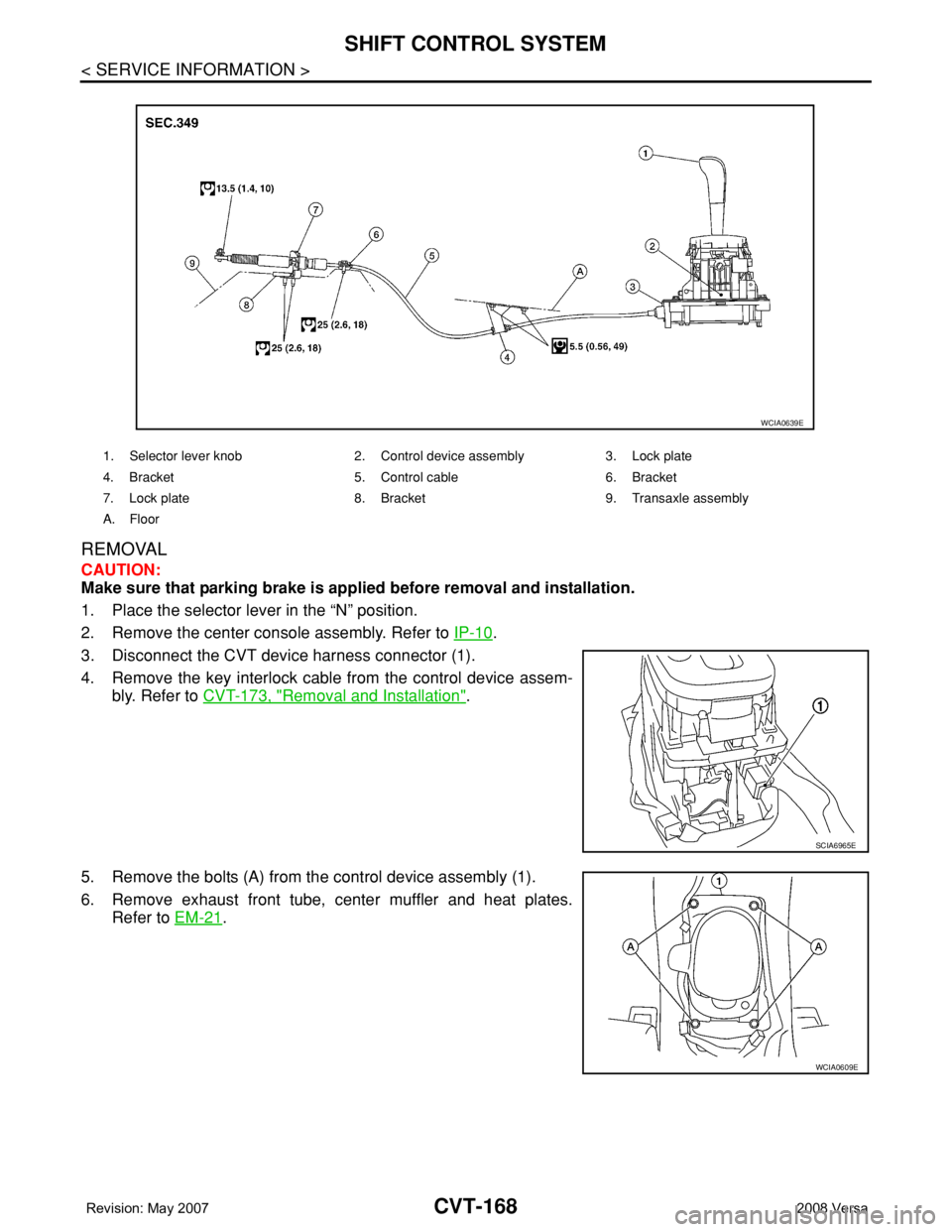
CVT-168
< SERVICE INFORMATION >
SHIFT CONTROL SYSTEM
REMOVAL
CAUTION:
Make sure that parking brake is applied before removal and installation.
1. Place the selector lever in the “N” position.
2. Remove the center console assembly. Refer to IP-10
.
3. Disconnect the CVT device harness connector (1).
4. Remove the key interlock cable from the control device assem-
bly. Refer to CVT-173, "
Removal and Installation".
5. Remove the bolts (A) from the control device assembly (1).
6. Remove exhaust front tube, center muffler and heat plates.
Refer to EM-21
.
1. Selector lever knob 2. Control device assembly 3. Lock plate
4. Bracket 5. Control cable 6. Bracket
7. Lock plate 8. Bracket 9. Transaxle assembly
A. Floor
WCIA0639E
SCIA6965E
WCIA0609E
Page 1095 of 2771
PREPARATION
EC-21
< SERVICE INFORMATION >
C
D
E
F
G
H
I
J
K
L
MA
EC
N
P O
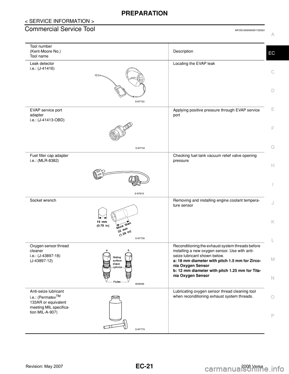
Commercial Service ToolINFOID:0000000001702553
Tool number
(Kent-Moore No.)
Tool nameDescription
Leak detector
i.e.: (J-41416)Locating the EVAP leak
EVAP service port
adapter
i.e.: (J-41413-OBD)Applying positive pressure through EVAP service
port
Fuel filler cap adapter
i.e.: (MLR-8382)Checking fuel tank vacuum relief valve opening
pressure
Socket wrench Removing and installing engine coolant tempera-
ture sensor
Oxygen sensor thread
cleaner
i.e.: (J-43897-18)
(J-43897-12)Reconditioning the exhaust system threads before
installing a new oxygen sensor. Use with anti-
seize lubricant shown below.
a: 18 mm diameter with pitch 1.5 mm for Zirco-
nia Oxygen Sensor
b: 12 mm diameter with pitch 1.25 mm for Tita-
nia Oxygen Sensor
Anti-seize lubricant
i.e.: (Permatex
TM
133AR or equivalent
meeting MIL specifica-
tion MIL-A-907)Lubricating oxygen sensor thread cleaning tool
when reconditioning exhaust system threads.
S-NT703
S-NT704
S-NT815
S-NT705
AEM488
S-NT779
Page 1097 of 2771
ENGINE CONTROL SYSTEM
EC-23
< SERVICE INFORMATION >
C
D
E
F
G
H
I
J
K
L
MA
EC
N
P O
*1: This sensor is not used to control the engine system under normal conditions.
*2: This signal is sent to the ECM through CAN communication line.
*3: ECM determines the start signal status by the signals of engine speed and battery voltage.
SYSTEM DESCRIPTION
The amount of fuel injected from the fuel injector is determined by the ECM. The ECM controls the length of
time the valve remains open (injection pulse duration). The amount of fuel injected is a program value in the
ECM memory. The program value is preset by engine operating conditions. These conditions are determined
by input signals (for engine speed and intake air) from the crankshaft position sensor (POS), camshaft position
sensor (PHASE) and the mass air flow sensor.
VARIOUS FUEL INJECTION INCREASE/DECREASE COMPENSATION
In addition, the amount of fuel injected is compensated to improve engine performance under various operat-
ing conditions as listed below.
• When starting the engine
• During acceleration
• Hot-engine operation
• When selector lever is changed from N to D (A/T and CVT models)
• High-load, high-speed operation
• During deceleration
• During high engine speed operation
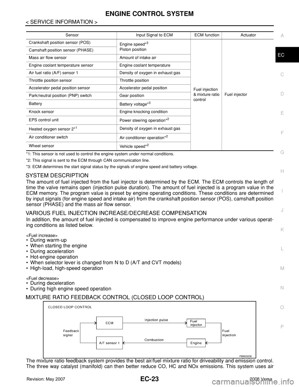
MIXTURE RATIO FEEDBACK CONTROL (CLOSED LOOP CONTROL)
The mixture ratio feedback system provides the best air/fuel mixture ratio for driveability and emission control.
The three way catalyst (manifold) can then better reduce CO, HC and NOx emissions. This system uses air
Sensor Input Signal to ECM ECM function Actuator
Crankshaft position sensor (POS)
Engine speed*
3
Piston position
Fuel injection
& mixture ratio
controlFuel injector Camshaft position sensor (PHASE)
Mass air flow sensor Amount of intake air
Engine coolant temperature sensor Engine coolant temperature
Air fuel ratio (A/F) sensor 1 Density of oxygen in exhaust gas
Throttle position sensor Throttle position
Accelerator pedal position sensor Accelerator pedal position
Park/neutral position (PNP) switch Gear position
Battery
Battery voltage*
3
Knock sensor Engine knocking condition
EPS control unit
Power steering operation*
2
Heated oxygen sensor 2*1Density of oxygen in exhaust gas
Air conditioner switch
Air conditioner operation*
2
Wheel sensor
Vehicle speed*2
PBIB3020E
Page 1098 of 2771
EC-24
< SERVICE INFORMATION >
ENGINE CONTROL SYSTEM
fuel ratio (A/F) sensor 1 in the exhaust manifold to monitor whether the engine operation is rich or lean. The
ECM adjusts the injection pulse width according to the sensor voltage signal. For more information about air
fuel ratio (A/F) sensor 1, refer to EC-213
. This maintains the mixture ratio within the range of stoichiometric
(ideal air/fuel mixture).
This stage is referred to as the closed loop control condition.
Heated oxygen sensor 2 is located downstream of the three way catalyst (manifold). Even if the switching
characteristics of air fuel ratio (A/F) sensor 1 shift, the air/fuel ratio is controlled to stoichiometric by the signal
from heated oxygen sensor 2.
Open Loop Control
The open loop system condition refers to when the ECM detects any of the following conditions. Feedback
control stops in order to maintain stabilized fuel combustion.
• Deceleration and acceleration
• High-load, high-speed operation
• Malfunction of air fuel ratio (A/F) sensor 1 or its circuit
• Insufficient activation of air fuel ratio (A/F) sensor 1 at low engine coolant temperature
• High engine coolant temperature
• During warm-up
• After shifting from N to D (A/T and CVT models)
• When starting the engine
MIXTURE RATIO SELF-LEARNING CONTROL
The mixture ratio feedback control system monitors the mixture ratio signal transmitted from air fuel ratio (A/F)
sensor 1. This feedback signal is then sent to the ECM. The ECM controls the basic mixture ratio as close to
the theoretical mixture ratio as possible. However, the basic mixture ratio is not necessarily controlled as orig-
inally designed. Both manufacturing differences (i.e., mass air flow sensor hot wire) and characteristic
changes during operation (i.e., fuel injector clogging) directly affect mixture ratio.
Accordingly, the difference between the basic and theoretical mixture ratios is monitored in this system. This is
then computed in terms of “injection pulse duration” to automatically compensate for the difference between
the two ratios.
“Fuel trim” refers to the feedback compensation value compared against the basic injection duration. Fuel trim
includes short term fuel trim and long term fuel trim.
“Short term fuel trim” is the short-term fuel compensation used to maintain the mixture ratio at its theoretical
value. The signal from air fuel ratio (A/F) sensor 1 indicates whether the mixture ratio is RICH or LEAN com-
pared to the theoretical value. The signal then triggers a reduction in fuel volume if the mixture ratio is rich, and
an increase in fuel volume if it is lean.
“Long term fuel trim” is overall fuel compensation carried out long-term to compensate for continual deviation
of the short term fuel trim from the central value. Such deviation will occur due to individual engine differences,
wear over time and changes in the usage environment.
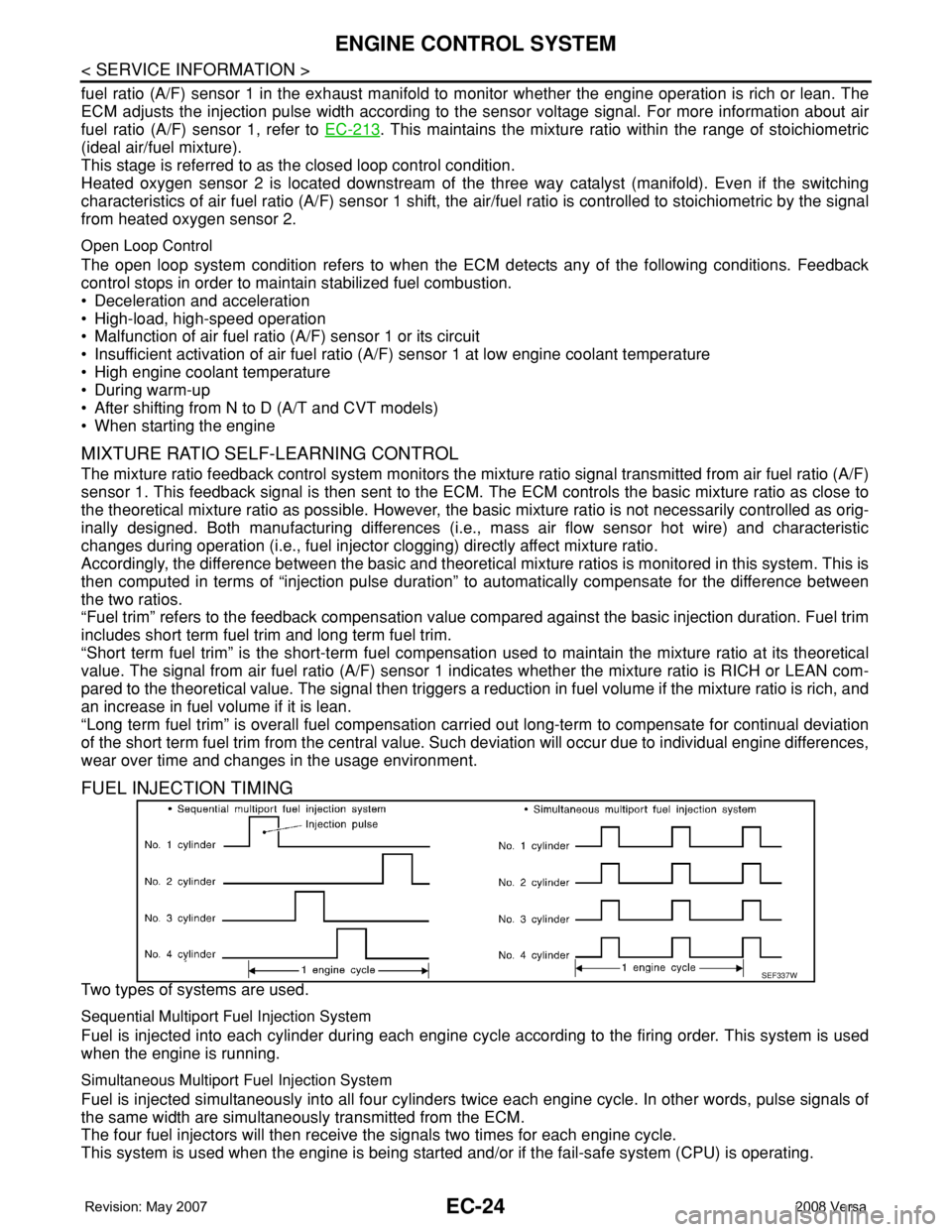
FUEL INJECTION TIMING
Two types of systems are used.
Sequential Multiport Fuel Injection System
Fuel is injected into each cylinder during each engine cycle according to the firing order. This system is used
when the engine is running.
Simultaneous Multiport Fuel Injection System
Fuel is injected simultaneously into all four cylinders twice each engine cycle. In other words, pulse signals of
the same width are simultaneously transmitted from the ECM.
The four fuel injectors will then receive the signals two times for each engine cycle.
This system is used when the engine is being started and/or if the fail-safe system (CPU) is operating.
SEF337W
Page 1138 of 2771

EC-64
< SERVICE INFORMATION >
ON BOARD DIAGNOSTIC (OBD) SYSTEM
C) without the same malfunction recurring. The “TIME” in “SELF-DIAGNOSTIC RESULTS” mode of CON-
SULT-II will count the number of times the vehicle is driven.
• The 1st trip DTC is not displayed when the self-diagnosis results in OK for the 2nd trip.
SUMMARY CHART
For details about patterns B and C under “Fuel Injection System” and “Misfire”, see "EXPLANATION FOR DRIVING PATTERNS FOR
“MISFIRE
For details about patterns A and B under “Other”, see "EXPLANATION FOR DRIVING PATTERNS FOR “MISFIRE
*1: Clear timing is at the moment OK is detected.
*2: Clear timing is when the same malfunction is detected in the 2nd trip.
RELATIONSHIP BETWEEN MIL, DTC, 1ST TRIP DTC AND DRIVING PATTERNS FOR “MISFIRE
Items Fuel Injection System Misfire Other
MIL (goes off) 3 (pattern B) 3 (pattern B) 3 (pattern B)
DTC, Freeze Frame Data (no
display)80 (pattern C) 80 (pattern C) 40 (pattern A)
1st Trip DTC (clear) 1 (pattern C), *1 1 (pattern C), *1 1 (pattern B)
1st Trip Freeze Frame Data
(clear)*1, *2 *1, *2 1 (pattern B)