fail-safe NISSAN TIIDA 2008 Service Repair Manual
[x] Cancel search | Manufacturer: NISSAN, Model Year: 2008, Model line: TIIDA, Model: NISSAN TIIDA 2008Pages: 2771, PDF Size: 60.61 MB
Page 13 of 2771

AT-1
TRANSMISSION/TRANSAXLE
D
E
F
G
H
I
J
K
L
M
SECTION AT
A
B
AT
N
O
P
CONTENTS
AUTOMATIC TRANSAXLE
SERVICE INFORMATION ............................5
INDEX FOR DTC .................................................5
Alphabetical Index .....................................................5
DTC No. Index ..........................................................5
PRECAUTIONS ...................................................7
Precaution for Supplemental Restraint System
(SRS) "AIR BAG" and "SEAT BELT PRE-TEN-
SIONER" ...................................................................
7
Precaution Necessary for Steering Wheel Rota-
tion After Battery Disconnect .....................................
7
Precaution for On Board Diagnosis (OBD) System
of A/T and Engine .....................................................
7
Precaution .................................................................8
Service Notice or Precaution .....................................9
PREPARATION ..................................................10
Special Service Tool ...............................................10
Commercial Service Tool ........................................13
A/T FLUID ...........................................................15
Checking A/T Fluid ..................................................15
Changing A/T Fluid .................................................15
A/T Fluid Cooler Cleaning .......................................16
A/T CONTROL SYSTEM ....................................19
Cross-Sectional View ..............................................19
Shift Mechanism ......................................................19
TCM Function ..........................................................27
CAN Communication ...............................................28
Input/Output Signal of TCM .....................................28
Line Pressure Control .............................................29
Shift Control ............................................................30
Lock-up Control .......................................................31
Engine Brake Control (Overrun Clutch Control) ......32
Control Valve ...........................................................34
Centrifugal Cancel Mechanism ...............................34
ON BOARD DIAGNOSTIC (OBD) SYSTEM ......36
Introduction .............................................................36
OBD-II Function for A/T System ..............................36
One or Two Trip Detection Logic of OBD-II .............36
OBD-II Diagnostic Trouble Code (DTC) ..................36
Malfunction Indicator Lamp (MIL) ............................38
TROUBLE DIAGNOSIS ....................................39
DTC Inspection Priority Chart ..................................39
Fail-Safe ..................................................................39
How to Perform Trouble Diagnosis for Quick and
Accurate Repair .......................................................
40
A/T Electrical Parts Location ...................................46
Circuit Diagram ........................................................47
Inspections Before Trouble Diagnosis .....................48
Road Test ................................................................52
Check Before Engine Is Started ..............................53
Check at Idle ............................................................53
Cruise Test - Part 1 .................................................55
Cruise Test - Part 2 .................................................58
Cruise Test - Part 3 .................................................59
Vehicle Speed at Which Gear Shifting Occurs ........61
Vehicle Speed at Which Lock-up Occurs/Releas-
es .............................................................................
61
Symptom Chart ........................................................61
TCM Terminal and Reference Value .......................71
CONSULT-III Function (A/T) ...................................73
Diagnosis Procedure without CONSULT-III ............78
DTC U1000 CAN COMMUNICATION LINE .....83
Description ...............................................................83
On Board Diagnosis Logic .......................................83
Possible Cause ........................................................83
DTC Confirmation Procedure ..................................83
Wiring Diagram - AT - CAN .....................................84
Diagnosis Procedure ...............................................85
DTC P0705 PARK/NEUTRAL POSITION
(PNP) SWITCH ..................................................
86
Description ...............................................................86
CONSULT-III Reference Value in Data Monitor
Mode ........................................................................
86
On Board Diagnosis Logic .......................................86
Possible Cause ........................................................86
Page 17 of 2771

INDEX FOR DTC
AT-5
< SERVICE INFORMATION >
D
E
F
G
H
I
J
K
L
MA
B
AT
N
O
P
SERVICE INFORMATION
INDEX FOR DTC
Alphabetical IndexINFOID:0000000001703149
NOTE:
If DTC “CAN COMM CIRCUIT” is displayed with other DTCs, first perform the trouble diagnosis for
DTC “CAN COMM CIRCUIT”. Refer to AT- 8 3
.
*1: These numbers is prescribed by SAE J2012.
*2: When the fail-safe operation occurs, the MIL illuminates.
*3: The MIL illuminates when both the “Revolution sensor signal” and the “Vehicle speed sensor signal” meet the fail-safe condition at
the same time.
DTC No. IndexINFOID:0000000001703150
NOTE:
If DTC “CAN COMM CIRCUIT” is displayed with other DTCs, first perform the trouble diagnosis for
DTC “CAN COMM CIRCUIT”. Refer to AT- 8 3
.
Items
(CONSULT-III screen terms)DTC
Reference page
CONSULT-III or GST
*1
A/T 1ST GR FNCTN P0731AT-105
A/T 2ND GR FNCTN P0732AT-108
A/T 3RD GR FNCTN P0733AT- 111
A/T 4TH GR FNCTN P0734AT- 11 4
A/T TCC S/V FNCTN P0744AT-124
ATF TEMP SEN/CIRC P0710AT- 9 1
BATT/FLUID TEMP SEN —AT-152
CAN COMM CIRCUIT U1000AT- 8 3
CONTROL UNIT (RAM) —AT-163
CONTROL UNIT (ROM) —AT-163
ENGINE SPEED SIG P0725AT-101
LINE PRESSURE S/V P0745AT-129
OVERRUN CLUTCH S/V P1760AT-144
PNP SW/CIRC P0705AT- 8 6
SHIFT SOLENOID/V A*2P0750AT-134
SHIFT SOLENOID/V B*2P0755AT-139
T/C CLUTCH SOL/V P0740AT- 11 9
TURBINE SENSOR —AT-158
VHCL SPEED SEN-A/T*3P0720AT- 9 6
VHCL SPEED SEN-MTR —AT-149
DTC
Items
(CONSULT-III screen terms) Reference page
CONSULT-III or GST
*1
P0705 PNP SW/CIRCAT- 8 6
P0710 ATF TEMP SEN/CIRCAT- 9 1
P0720
VHCL SPEED SEN-A/T*3AT- 9 6
P0725 ENGINE SPEED SIGAT- 1 0 1
P0731 A/T 1ST GR FNCTNAT- 1 0 5
Page 18 of 2771

AT-6
< SERVICE INFORMATION >
INDEX FOR DTC
*1: These numbers is prescribed by SAE J2012.
*2: When the fail-safe operation occurs, the MIL illuminates.
*3: The MIL illuminates when both the “Revolution sensor signal” and the “Vehicle speed sensor signal” meet the fail-safe condition at
the same time.P0732 A/T 2ND GR FNCTNAT- 1 0 8
P0733 A/T 3RD GR FNCTNAT- 111
P0734 A/T 4TH GR FNCTNAT- 11 4
P0740 T/C CLUTCH SOL/VAT- 11 9
P0744 A/T TCC S/V FNCTNAT- 1 2 4
P0745 LINE PRESSURE S/VAT- 1 2 9
P0750
SHIFT SOLENOID/V A*2AT- 1 3 4
P0755
SHIFT SOLENOID/V B*2AT- 1 3 9
P1760 OVERRUN CLUTCH S/VAT- 1 4 4
U1000 CAN COMM CIRCUITAT- 8 3
— BATT/FLUID TEMP SENAT- 1 5 2
— CONTROL UNIT (RAM)AT- 1 6 3
— CONTROL UNIT (ROM)AT- 1 6 3
— TURBINE SENSORAT- 1 5 8
— VHCL SPEED SEN-MTRAT- 1 4 9
DTC
Items
(CONSULT-III screen terms) Reference page
CONSULT-III or GST
*1
Page 39 of 2771
A/T CONTROL SYSTEM
AT-27
< SERVICE INFORMATION >
D
E
F
G
H
I
J
K
L
MA
B
AT
N
O
P
TCM FunctionINFOID:0000000001703163
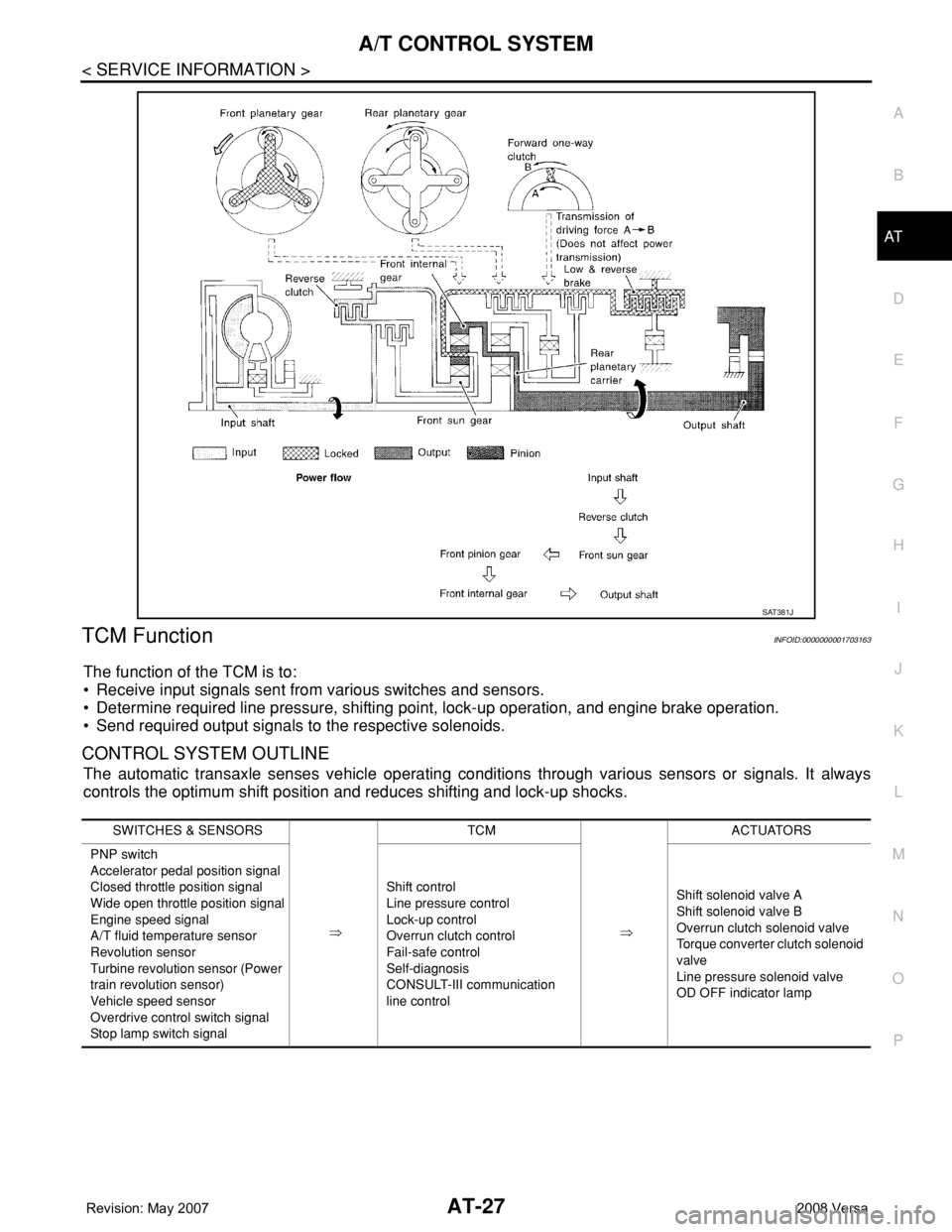
The function of the TCM is to:
• Receive input signals sent from various switches and sensors.
• Determine required line pressure, shifting point, lock-up operation, and engine brake operation.
• Send required output signals to the respective solenoids.
CONTROL SYSTEM OUTLINE
The automatic transaxle senses vehicle operating conditions through various sensors or signals. It always
controls the optimum shift position and reduces shifting and lock-up shocks.
SAT381J
SWITCHES & SENSORS
⇒TCM
⇒ACTUATORS
PNP switch
Accelerator pedal position signal
Closed throttle position signal
Wide open throttle position signal
Engine speed signal
A/T fluid temperature sensor
Revolution sensor
Turbine revolution sensor (Power
train revolution sensor)
Vehicle speed sensor
Overdrive control switch signal
Stop lamp switch signalShift control
Line pressure control
Lock-up control
Overrun clutch control
Fail-safe control
Self-diagnosis
CONSULT-III communication
line controlShift solenoid valve A
Shift solenoid valve B
Overrun clutch solenoid valve
Torque converter clutch solenoid
valve
Line pressure solenoid valve
OD OFF indicator lamp
Page 40 of 2771
AT-28
< SERVICE INFORMATION >
A/T CONTROL SYSTEM
CONTROL SYSTEM DIAGRAM
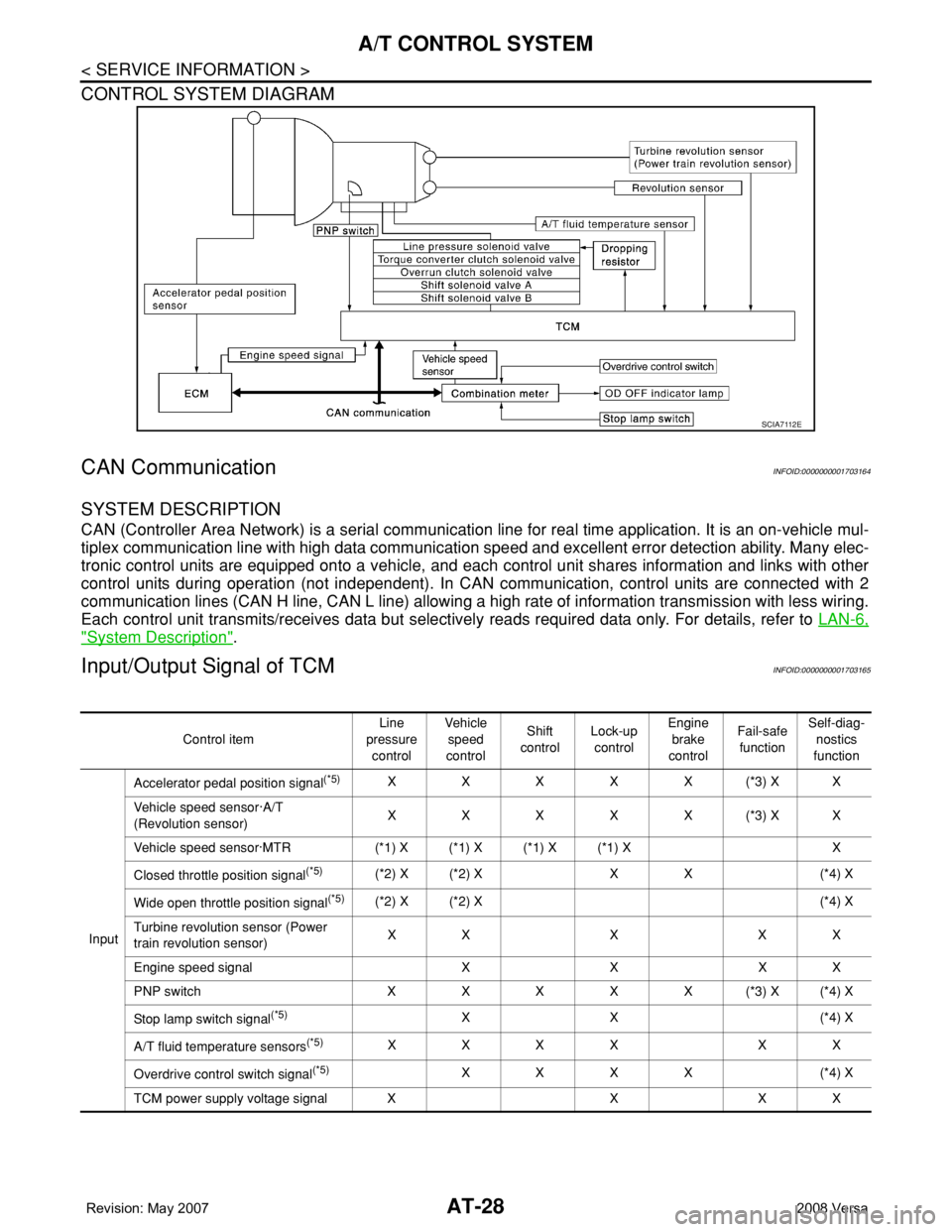
CAN CommunicationINFOID:0000000001703164
SYSTEM DESCRIPTION
CAN (Controller Area Network) is a serial communication line for real time application. It is an on-vehicle mul-
tiplex communication line with high data communication speed and excellent error detection ability. Many elec-
tronic control units are equipped onto a vehicle, and each control unit shares information and links with other
control units during operation (not independent). In CAN communication, control units are connected with 2
communication lines (CAN H line, CAN L line) allowing a high rate of information transmission with less wiring.
Each control unit transmits/receives data but selectively reads required data only. For details, refer to LAN-6,
"System Description".
Input/Output Signal of TCMINFOID:0000000001703165
SCIA7112E
Control itemLine
pressure
controlVehicle
speed
controlShift
controlLock-up
controlEngine
brake
controlFail-safe
functionSelf-diag-
nostics
function
InputAccelerator pedal position signal
(*5)XXXXX(*3) XX
Vehicle speed sensor·A/T
(Revolution sensor)XXXXX(*3) XX
Vehicle speed sensor·MTR (*1) X (*1) X (*1) X (*1) X X
Closed throttle position signal
(*5)(*2) X (*2) X X X (*4) X
Wide open throttle position signal
(*5)(*2) X (*2) X (*4) X
Turbine revolution sensor (Power
train revolution sensor)XXXXX
Engine speed signal X X X X
PNP switch XXXXX(*3) X(*4) X
Stop lamp switch signal
(*5)XX (*4) X
A/T fluid temperature sensors
(*5)XXXX XX
Overdrive control switch signal
(*5)XXXX (*4) X
TCM power supply voltage signal X X X X
Page 41 of 2771
A/T CONTROL SYSTEM
AT-29
< SERVICE INFORMATION >
D
E
F
G
H
I
J
K
L
MA
B
AT
N
O
P
*1: Spare for vehicle speed sensor·A/T (revolution sensor)
*2: Spare for accelerator pedal position signal
*3: If these input and output signals are different, the TCM triggers the fail-safe function.
*4: Used as a condition for starting self-diagnostics; if self-diagnosis are not started, it is judged that there is some kind of error.
*5: Input by CAN communications.
*6: Output by CAN communications.
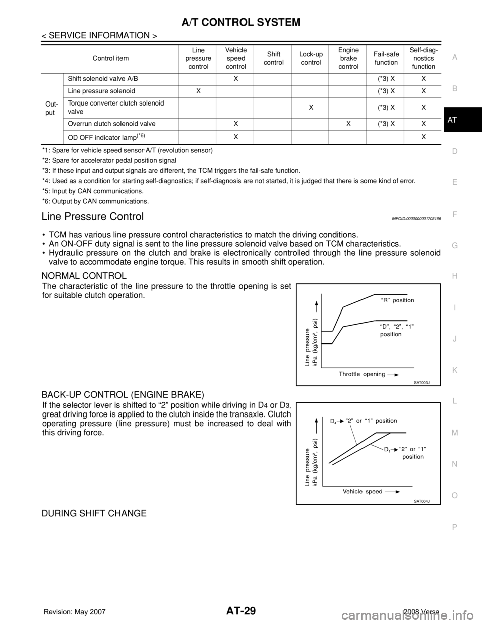
Line Pressure ControlINFOID:0000000001703166
• TCM has various line pressure control characteristics to match the driving conditions.
• An ON-OFF duty signal is sent to the line pressure solenoid valve based on TCM characteristics.
• Hydraulic pressure on the clutch and brake is electronically controlled through the line pressure solenoid
valve to accommodate engine torque. This results in smooth shift operation.
NORMAL CONTROL
The characteristic of the line pressure to the throttle opening is set
for suitable clutch operation.
BACK-UP CONTROL (ENGINE BRAKE)
If the selector lever is shifted to “2” position while driving in D4 or D3,
great driving force is applied to the clutch inside the transaxle. Clutch
operating pressure (line pressure) must be increased to deal with
this driving force.
DURING SHIFT CHANGE
Out-
putShift solenoid valve A/B X (*3) X X
Line pressure solenoid X (*3) X X
Torque converter clutch solenoid
valveX(*3) XX
Overrun clutch solenoid valve X X (*3) X X
OD OFF indicator lamp
(*6)XX Control itemLine
pressure
controlVeh icl e
speed
controlShift
controlLock-up
controlEngine
brake
controlFail-safe
functionSelf-diag-
nostics
function
SAT003J
SAT004J
Page 51 of 2771
TROUBLE DIAGNOSIS
AT-39
< SERVICE INFORMATION >
D
E
F
G
H
I
J
K
L
MA
B
AT
N
O
P
TROUBLE DIAGNOSIS
DTC Inspection Priority ChartINFOID:0000000001703177
If some DTCs are displayed at the same time, perform inspections one by one based on the following priority
chart.
NOTE:
If DTC “CAN COMM CIRCUIT” is displayed with other DTCs, first perform the trouble diagnosis for
DTC “CAN COMM CIRCUIT”. Refer to AT- 8 3
.
Fail-SafeINFOID:0000000001703178
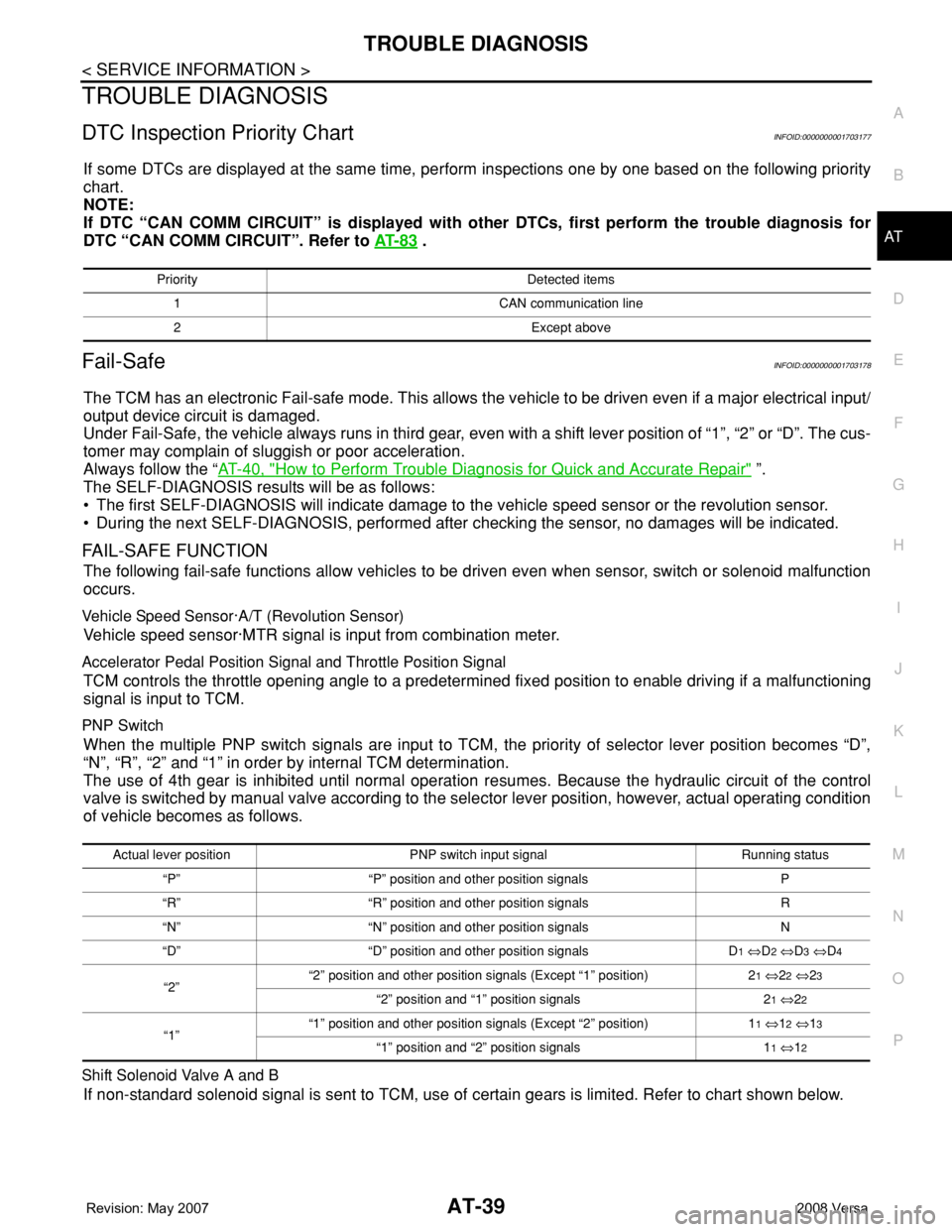
The TCM has an electronic Fail-safe mode. This allows the vehicle to be driven even if a major electrical input/
output device circuit is damaged.
Under Fail-Safe, the vehicle always runs in third gear, even with a shift lever position of “1”, “2” or “D”. The cus-
tomer may complain of sluggish or poor acceleration.
Always follow the “AT-40, "
How to Perform Trouble Diagnosis for Quick and Accurate Repair" ”.
The SELF-DIAGNOSIS results will be as follows:
• The first SELF-DIAGNOSIS will indicate damage to the vehicle speed sensor or the revolution sensor.
• During the next SELF-DIAGNOSIS, performed after checking the sensor, no damages will be indicated.
FAIL-SAFE FUNCTION
The following fail-safe functions allow vehicles to be driven even when sensor, switch or solenoid malfunction
occurs.
Vehicle Speed Sensor·A/T (Revolution Sensor)
Vehicle speed sensor·MTR signal is input from combination meter.
Accelerator Pedal Position Signal and Throttle Position Signal
TCM controls the throttle opening angle to a predetermined fixed position to enable driving if a malfunctioning
signal is input to TCM.
PNP Switch
When the multiple PNP switch signals are input to TCM, the priority of selector lever position becomes “D”,
“N”, “R”, “2” and “1” in order by internal TCM determination.
The use of 4th gear is inhibited until normal operation resumes. Because the hydraulic circuit of the control
valve is switched by manual valve according to the selector lever position, however, actual operating condition
of vehicle becomes as follows.
Shift Solenoid Valve A and B
If non-standard solenoid signal is sent to TCM, use of certain gears is limited. Refer to chart shown below.
Priority Detected items
1 CAN communication line
2 Except above
Actual lever position PNP switch input signal Running status
“P” “P” position and other position signals P
“R” “R” position and other position signals R
“N” “N” position and other position signals N
“D” “D” position and other position signals D
1 ⇔D2 ⇔D3 ⇔D4
“2”“2” position and other position signals (Except “1” position) 21 ⇔22 ⇔23
“2” position and “1” position signals 21 ⇔22
“1”“1” position and other position signals (Except “2” position) 11 ⇔12 ⇔13
“1” position and “2” position signals 11 ⇔12
Page 55 of 2771
TROUBLE DIAGNOSIS
AT-43
< SERVICE INFORMATION >
D
E
F
G
H
I
J
K
L
MA
B
AT
N
O
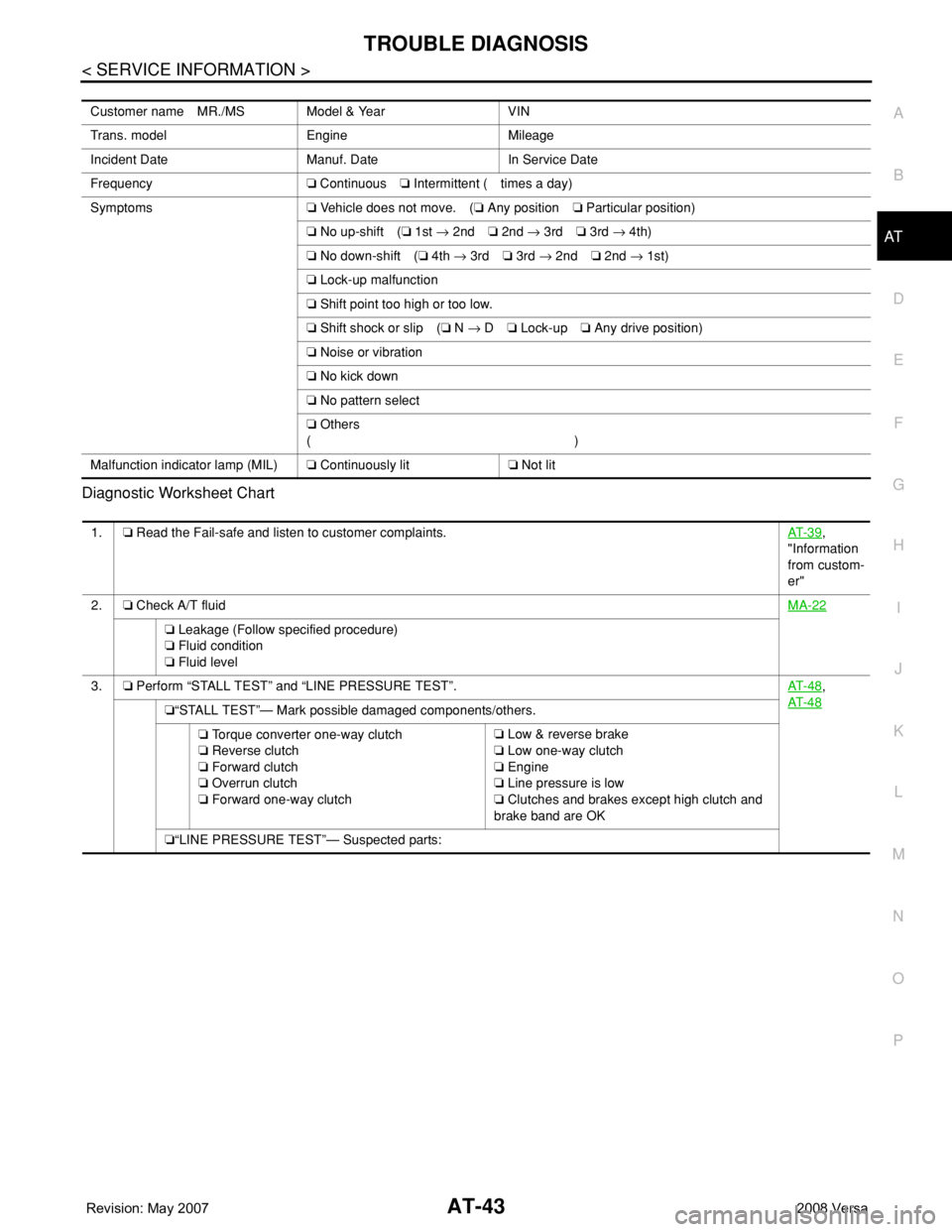
P Diagnostic Worksheet Chart
Customer name MR./MS Model & Year VIN
Trans. model Engine Mileage
Incident Date Manuf. Date In Service Date
Frequency❏ Continuous❏ Intermittent ( times a day)
Symptoms❏ Vehicle does not move. (❏ Any position❏ Particular position)
❏ No up-shift (❏ 1st → 2nd❏ 2nd → 3rd❏ 3rd → 4th)
❏ No down-shift (❏ 4th → 3rd❏ 3rd → 2nd❏ 2nd → 1st)
❏ Lock-up malfunction
❏ Shift point too high or too low.
❏ Shift shock or slip (❏ N → D❏ Lock-up❏ Any drive position)
❏ Noise or vibration
❏ No kick down
❏ No pattern select
❏ Others
()
Malfunction indicator lamp (MIL)❏ Continuously lit❏ Not lit
1.❏ Read the Fail-safe and listen to customer complaints.AT- 3 9,
"Information
from custom-
er"
2.❏ Check A/T fluidMA-22
❏ Leakage (Follow specified procedure)
❏ Fluid condition
❏ Fluid level
3.❏ Perform “STALL TEST” and “LINE PRESSURE TEST”.AT- 4 8
,
AT- 4 8
❏“STALL TEST”— Mark possible damaged components/others.
❏ Torque converter one-way clutch
❏ Reverse clutch
❏ Forward clutch
❏ Overrun clutch
❏ Forward one-way clutch❏ Low & reverse brake
❏ Low one-way clutch
❏ Engine
❏ Line pressure is low
❏ Clutches and brakes except high clutch and
brake band are OK
❏“LINE PRESSURE TEST”— Suspected parts:
Page 89 of 2771
TROUBLE DIAGNOSIS
AT-77
< SERVICE INFORMATION >
D
E
F
G
H
I
J
K
L
MA
B
AT
N
O
P
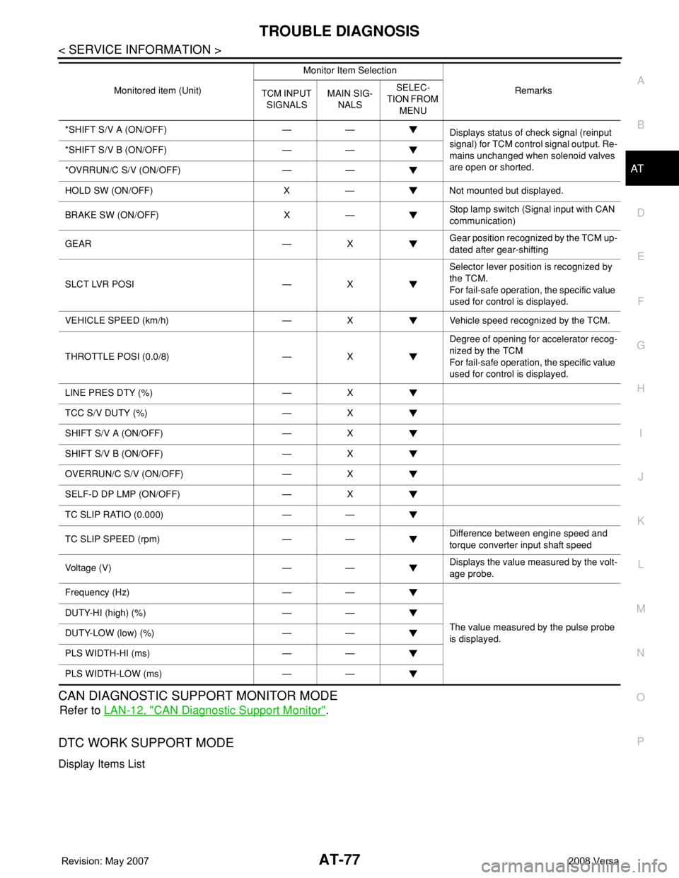
CAN DIAGNOSTIC SUPPORT MONITOR MODE
Refer to LAN-12, "CAN Diagnostic Support Monitor".
DTC WORK SUPPORT MODE
Display Items List
*SHIFT S/V A (ON/OFF) — —
Displays status of check signal (reinput
signal) for TCM control signal output. Re-
mains unchanged when solenoid valves
are open or shorted. *SHIFT S/V B (ON/OFF) — —
*OVRRUN/C S/V (ON/OFF) — —
HOLD SW (ON/OFF) X — Not mounted but displayed.
BRAKE SW (ON/OFF) X —Stop lamp switch (Signal input with CAN
communication)
GEAR — XGear position recognized by the TCM up-
dated after gear-shifting
SLCT LVR POSI — XSelector lever position is recognized by
the TCM.
For fail-safe operation, the specific value
used for control is displayed.
VEHICLE SPEED (km/h) — X Vehicle speed recognized by the TCM.
THROTTLE POSI (0.0/8) — XDegree of opening for accelerator recog-
nized by the TCM
For fail-safe operation, the specific value
used for control is displayed.
LINE PRES DTY (%) — X
TCC S/V DUTY (%) — X
SHIFT S/V A (ON/OFF) — X
SHIFT S/V B (ON/OFF) — X
OVERRUN/C S/V (ON/OFF) — X
SELF-D DP LMP (ON/OFF) — X
TC SLIP RATIO (0.000) — —
TC SLIP SPEED (rpm) — —Difference between engine speed and
torque converter input shaft speed
Voltage (V) — —Displays the value measured by the volt-
age probe.
Frequency (Hz) — —
The value measured by the pulse probe
is displayed. DUTY-HI (high) (%) — —
DUTY-LOW (low) (%) — —
PLS WIDTH-HI (ms) — —
PLS WIDTH-LOW (ms) — —Monitored item (Unit)Monitor Item Selection
Remarks
TCM INPUT
SIGNALSMAIN SIG-
NALSSELEC-
TION FROM
MENU
Page 184 of 2771
AT-172
< SERVICE INFORMATION >
SHIFT POSITION INDICATOR CIRCUIT
SHIFT POSITION INDICATOR CIRCUIT
DescriptionINFOID:0000000001703331
TCM sends the switch signals to combination meter via CAN communication line. Then selector lever position
is indicated on the shift position indicator.
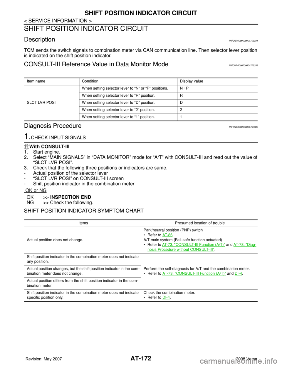
CONSULT-III Reference Value in Data Monitor ModeINFOID:0000000001703332
Diagnosis ProcedureINFOID:0000000001703333
1.CHECK INPUT SIGNALS
With CONSULT-III
1. Start engine.
2. Select “MAIN SIGNALS” in “DATA MONITOR” mode for “A/T” with CONSULT-III and read out the value of
“SLCT LVR POSI”.
3. Check that the following three positions or indicators are same.
- Actual position of the selector lever
- “SLCT LVR POSI” on CONSULT-III screen
- Shift position indicator in the combination meter
OK or NG
OK >>INSPECTION END
NG >> Check the following.
SHIFT POSITION INDICATOR SYMPTOM CHART
Item name Condition Display value
SLCT LVR POSIWhen setting selector lever to “N” or “P” positions. N · P
When setting selector lever to “R” position. R
When setting selector lever to “D” position. D
When setting selector lever to “2” position. 2
When setting selector lever to “1” position. 1
Items Presumed location of trouble
Actual position does not change.Park/neutral position (PNP) switch
• Refer to AT- 8 6
.
A/T main system (Fail-safe function actuated)
•Refer to AT- 7 3 , "
CONSULT-III Function (A/T)" and AT- 7 8 , "Diag-
nosis Procedure without CONSULT-III".
Shift position indicator in the combination meter does not indicate
any position.
Perform the self-diagnosis for A/T and the combination meter.
• Refer to AT- 7 3 , "
CONSULT-III Function (A/T)" and DI-4. Actual position changes, but the shift position indicator in the com-
bination meter does not change.
Actual position differs from the shift position indicator in the com-
bination meter.
Shift position indicator in the combination meter does not indicate
specific position only.Check the combination meter.
• Refer to DI-4
.