wiper NISSAN TIIDA 2009 Service Owner's Guide
[x] Cancel search | Manufacturer: NISSAN, Model Year: 2009, Model line: TIIDA, Model: NISSAN TIIDA 2009Pages: 4331, PDF Size: 58.04 MB
Page 3386 of 4331
.
22. Remove wiper & washer switch. Refer to WW-23, " Removal and Installation of Front Wiper and Washer
Switch " .
23. Remove hood opener handle and fuel filler lid opener handle. Refer to BL-15, " Removal and Installation of
Hood Lock Control " .
24. Remove screws, and then remove instrument panel & pad from passenger door opening portion.
Installation
Installation is in the reverse order of removal.
CLUSTER LID A
Removal
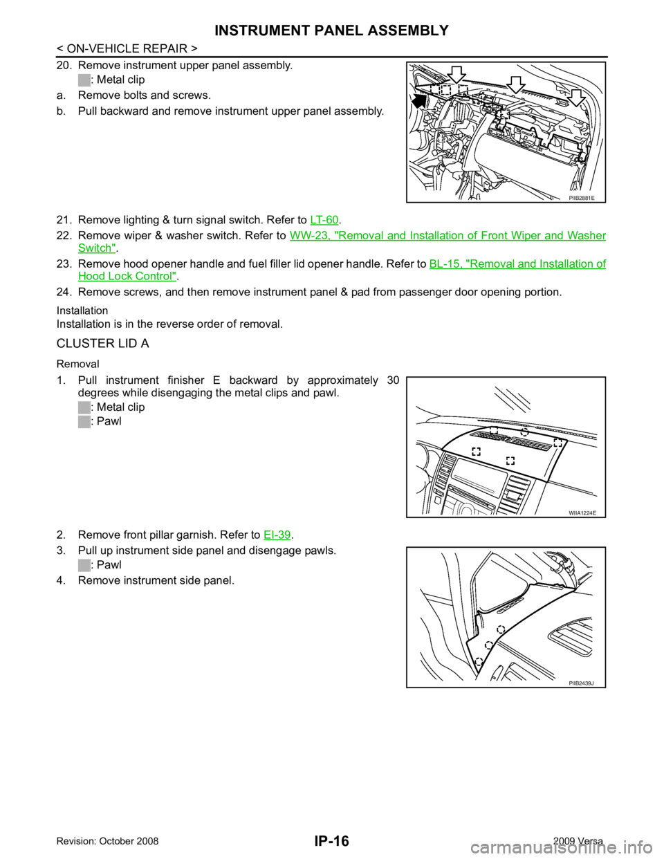
1. Pull instrument finisher E backward by approximately 30 degrees while disengaging the metal clips and pawl.
: Metal clip
: Pawl
2. Remove front pillar garnish. Refer to EI-39 .
3. Pull up instrument side panel and disengage pawls. : Pawl
4. Remove instrument side panel. WIIA1224E
PIIB2439J
Page 3422 of 4331

LAN
N
O P
Engine status signal T R
Fuel consumption monitor signal T R
Malfunction indicator lamp signal T R
Wide open throttle position signal T R R
A/C switch signal R T
Blower fan motor switch signal R T
Buzzer output signal T R
T R
Day time running light request signal *3
T R
Door lock/unlock status signal T R
Door switch signal T R R R
Front wiper request signal T R
High beam request signal T R R
Horn chirp signal T R
Ignition switch signal T R
Low beam request signal T R
Position lights request signal T R R
Rear window defogger switch signal T R
Sleep/wake up signal R T
T R R R
Theft warning horn request signal T R
Tire pressure signal *4
T R
Trunk open/close status signal T R
Turn indicator signal T R
EPS operation signal R T
EPS warning lamp signal T R
Door lock/unlock/trunk open request signal R T
Hazard request signal R T
Ignition knob switch signal R T
KEY warning lamp signal T R
LOCK warning lamp signal T R
Panic alarm request signal R T
Fuel level sensor signal R T
Overdrive control switch signal T R R
P/N range signal T R
Stop lamp switch signal T R R
Vehicle speed signal R R R R T
R R R T R
R*5
T*5
ABS warning lamp signal R T
Brake warning lamp signal R T
A/T check indicator signal R T Signal name/Connecting unitECM
BCM EPS
I-KEY
M&AABS
TCM *1
TCM *2
IPDM-E
Page 3669 of 4331
LT
N
O P
Terminal and Reference Value for BCM
INFOID:0000000004306594
Refer to BCS-11, " Terminal and Reference Value for BCM " .
CONSULT-III Function (BCM) INFOID:0000000004306595
Refer to LT-11, " CONSULT-III Function (BCM) " .
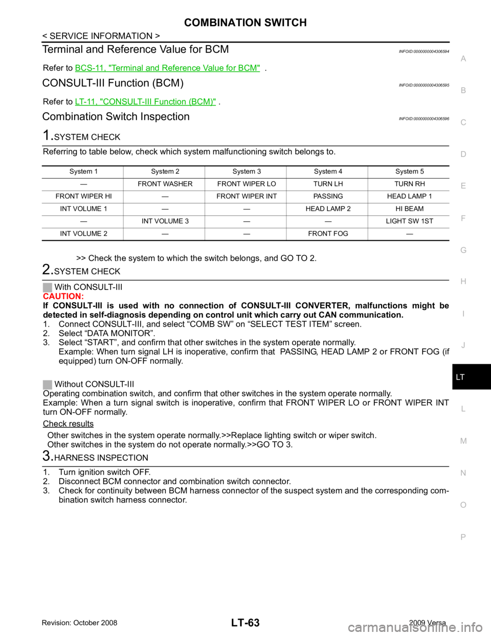
Combination Switch Inspection INFOID:0000000004306596Other switches in the system operate normall
y.>>Replace lighting switch or wiper switch.
Other switches in the system do not operate normally.>>GO TO 3.
Page 3671 of 4331
LT
N
O P
OK or NG OK >> Open circuit in combination switch, GO TO 5.
NG >> Replace BCM. Refer to BCS-18, " Removal and Installation of BCM " .
.
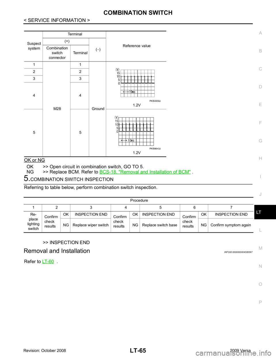
Suspect
system Terminal
Reference value
(+)
(− )
Combination
switch
connector Terminal
1
M28 1
Ground 1.2V
2 2
3 3
4 4
5 5 1.2V PKIB8643J
Procedure
1 2 3 4 5 6 7
Re-
place
lighting switch Confirm
check
results OK INSPECTION END
Confirm
check
results OK INSPECTION END
Confirm
check
results OK INSPECTION END
NG Replace wiper switch NG Replace switch base NG Confirm symptom again
Page 3749 of 4331

Tire "
Rotation "
Rotation "
Tire Pressure Monitor-
ing System (TPMS)
t ransmitter compo-
nents Replace the TPMS transmitter grommet seal, valve core and cap when the tires
are replaced due to wear or age. WT-8 Wheel Align-
ment Inspection " and
WT-7, " Balancing
Wheels "
LOCKS, HING-
ES AND HOOD LATCH :
Lubricating Locks, Hing-
es and Hood Latch "
Item
Reference page
Warning lamps and
chimes Make sure that all warning lamps and chimes are operating properly. —
Windshield wiper and
washer Check that the wipers and washer operate properly and that the wipers do not
streak. —
Windshield defroster Check that the air comes out of the defroster outlets properly and in sufficient
quantity when operating the heater or air conditioning. —
Steering wheel Check that it has the specified play. Be sure to check for changes in the steering
condition, such as excessive play, hard steering or strange noises.
Free play: Less than 35 mm (1.38 in) —
Seats Check seat position controls such as seat adjusters, seat back recliner, etc. to
make sure they operate smoothly and that all latches lock securely in every po-
sition. Check that the head restraints move up and down smoothly and that the
locks (if equipped) hold securely in all latched positions. Check that the latches
lock securely for folding-down rear seat backs. —
Page 4001 of 4331

Item name
CONSULT-III
screen display Display or unit Monitor item selection
Description
ALL
SIGNALS MAIN
SIGNALS SELECTION
FROM MENU
Motor fan request MOTOR FAN
REQ 1/2/3/4 X X X Signal status input from ECM
Compressor re-
quest AC COMP REQ ON/OFF X X X Signal status input from ECM
Parking, license,
and tail lamp re-
quest TAIL & CLR REQ ON/OFF X X X Signal status input from BCM
Headlamp low
beam request HL LO REQ ON/OFF X X X Signal status input from BCM
Headlamp high
beam request HL HI REQ ON/OFF X X X Signal
status input from BCM
Front fog request FR FOG REQ ON/OFF X X X Signal status input from BCM
FR wiper request FR WIP REQ STOP/1LO/LO/HI X X X Signal status input from BCM
Wiper auto stop WIP AUTO
STOP ACT P/STOP P X X X Output status of IPDM E/R
Wiper protection WIP PROT OFF/LS/HS/Block X X X Control status of IPDM E/R
Starter request ST RLY REQ ON/OFF X X Status of input signal (*1)
Ignition relay
status IGN RLY ON/OFF X X X Ignition relay status monitored
with IPDM E/R
Rear defogger re-
quest RR DEF REQ ON/OFF X X X Signal status input from BCM
Oil pressure
switch OIL P SW OPEN/CLOSE X X
Signal status input from IPDM
E/R
Hood switch HOOD SW (*2) OFF X X Signal status input from IPDM
E/R
Page 4002 of 4331
PG
N
O P
*1 Perform monitoring of IPDM E/R data with the ignition switch ON. When the ignition switch is in ACC position, display may no
t be cor-
rect.
*2 This item is displayed, but does not function.
CAN DIAG SUPPORT MNTR Refer to LAN-10, " Description " .
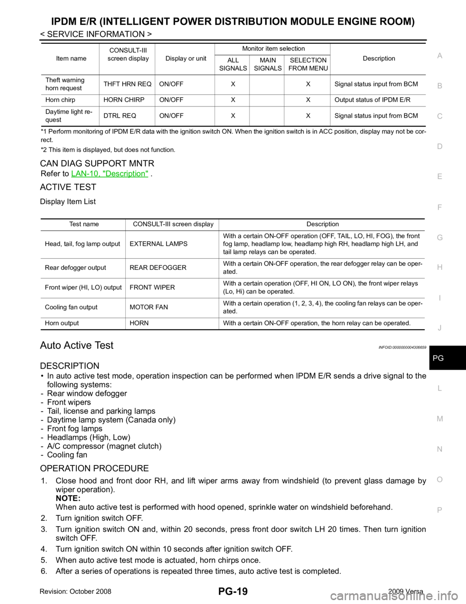
ACTIVE TEST
Display Item List
Auto Active Test INFOID:0000000004306659
DESCRIPTION • In auto active test mode, operation inspection can be performed when IPDM E/R sends a drive signal to the
following systems:
- Rear window defogger
- Front wipers
- Tail, license and parking lamps
- Daytime lamp system (Canada only)
- Front fog lamps
- Headlamps (High, Low)
- A/C compressor (magnet clutch)
- Cooling fan
OPERATION PROCEDURE 1. Close hood and front door RH, and lift wiper arms away from windshield (to prevent glass damage by
wiper operation).
NOTE:
When auto active test is performed with hood opened, sprinkle water on windshield beforehand.
2. Turn ignition switch OFF.
3. Turn ignition switch ON and, within 20 seconds, pre ss front door switch LH 20 times. Then turn ignition
switch OFF.
4. Turn ignition switch ON within 10 seconds after ignition switch OFF.
5. When auto active test mode is actuated, horn chirps once.
6. After a series of operations is repeated th ree times, auto active test is completed.
Theft warning
horn request THFT HRN REQ ON/OFF X X Signal status input from BCM
Horn chirp HORN CHIRP ON/OFF X X O utput status of IPDM E/R
Daytime light re-
quest DTRL REQ ON/OFF X X Signal
status input from BCM
Item name
CONSULT-III
screen display Display or unit Monitor item selection
Description
ALL
SIGNALS MAIN
SIGNALS SELECTION
FROM MENU Test name CONSULT-III screen display Description
Head, tail, fog lamp output EXTERNAL LAMPS With a certain ON-OFF operation (OFF, TAIL, LO, HI, FOG), the front
fog lamp, headlamp low, headlamp high RH, headlamp high LH, and
tail lamp relays can be operated.
Rear defogger output REAR DEFOGGER With a certain ON-OFF operation, the rear defogger relay can be oper-
ated.
Front wiper (HI, LO) output FRONT WIPER With a certain operation (OFF, HI ON, LO ON), the front wiper relays
(Lo, Hi) can be operated.
Cooling fan output MOTOR FAN With a certain operation (1, 2, 3, 4), the cooling fan relays can be oper-
ated.
Horn output HORN With a certain ON-OFF operation, the horn relay can be operated.
Page 4008 of 4331

PG
N
O P
24 Y Cooling fan relay-3 Output —
Conditions correct for cooling
fan high operation Battery voltage
Conditions not correct for
cooling fan high operation 0V
26 O Tail lamp relay (park-
ing lamps) Output — Lighting switch in 2nd position Battery voltage
27 BR Tail lamp relay (park-
ing lamps) Output — Lighting switch in 2nd position Battery voltage
28 GR Tail lamp relay (park-
ing lamps) Output — Lighting switch in 2nd position Battery voltage
29 P Tail lamp relay (park-
ing lamps) Output — Lighting switch in 2nd position Battery voltage
30
(A/T
only) R Fuse 54 Output — Ignition switch ON or START Battery voltage
Ignition switch OFF or ACC 0V
31 O Fuse 55 Output — Ignition switch ON or START Battery voltage
Ignition switch OFF or ACC 0V
32 L Wiper high speed sig-
nal OutputON or
START Wiper switch OFF, LO, INT 0V
HI Battery voltage
33 Y Wiper low speed sig-
nal OutputON or
START Wiper switch OFF 0V
LO or INT Battery voltage
35 BR Starter relay (inhibit
switch) InputON or
START Selector lever in "P" or "N"
(CVT or A/T) or clutch pedal
depressed (M/T) Battery voltage
Selector lever any other posi-
tion (CVT or A/T) or clutch
pedal released (M/T) 0V
36 BR Fuel pump relay Output — Ignition switch ON or START Battery voltage
Ignition switch OFF or ACC 0V
37 G Oil pressure switch Input ON or
START Engine running and oil pres-
sure within specification Battery voltage
Engine not running or oil pres-
sure below specification 0V
38 R Wiper auto stop signal Input ON or
START Wipers not in park position Battery voltage
Wipers in park position 0V
39 B Ground Input — — 0V
40 P CAN-L — ON — —
41 L CAN-H — ON — —
45 R Horn relay control Input — Horn switch PUSHED, alarm
switch activated or door lock/
unlock is confirmed when op-
erating lock system via the
keyfob 0V
Horn switch released, alarm
not active, keyfob not active Battery voltage
46 Y Throttle control motor
relay control Input —Ignition switch ON or START 0V
Ignition switch OFF or ACC Battery voltage
47 GR Fuel pump relay con-
trol Input —Ignition switch ON or START 0V
Ignition switch OFF or ACC Battery voltage
Terminal
Wire
color Signal name Signal
input/
output Measuring condition
Reference value
(Approx.)
Ignition
switch Operation or condition
Page 4042 of 4331

PG
N
O P
STM CVT Step Motor
STOP/L LT Stop Lamp
TCV AT Torque Converter Clutch Solenoid Valve
TCV CVT Torque Converter Clutch Solenoid Valve
T/LID BL Trunk Lid Opener
T/WARN WT Low Tire Pr essure Warning System
TAIL/L LT Parking, License and Tail Lamps
TPS1 EC Throttle Position Sensor
TPS2 EC Throttle Position Sensor
TPS3 EC Throttle Position Sensor
TURN LT Turn Signal and Hazard Warning Lamps
VEHSEC BL Vehicle Security (Theft Warning) System
VENT/V EC EVAP Canister Vent Control Valve
VSSA/T AT Vehicle Speed Sensor A/T (Revolution Sensor)
VSSMTR AT Vehicle Speed Sensor MTR
WARN DI Warning Lamps
WINDOW GW Power Window
WIP/R WW Rear Wiper and Washer
WIPER WW Front Wiper and Washer
Page 4227 of 4331
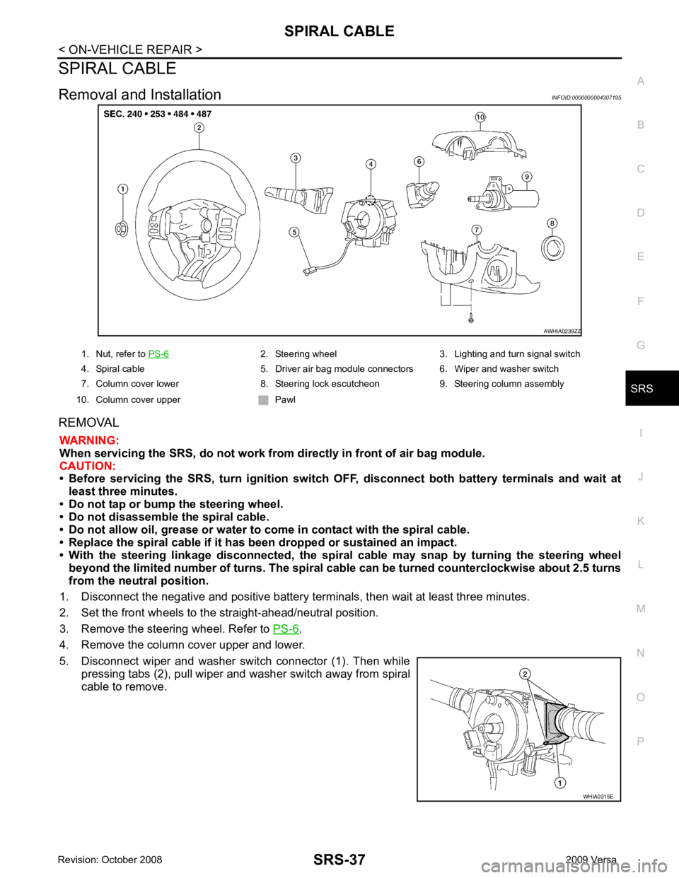
SRS
N
O P
SPIRAL CABLE
Removal and Installation INFOID:0000000004307195
REMOVAL WARNING:
When servicing the SRS, do not work from directly in front of air bag module.
CAUTION:
• Before servicing the SRS, turn ignition switch OFF, disconnect both battery terminals and wait at
least three minutes.
• Do not tap or bump the steering wheel.
• Do not disassemble the spiral cable.
• Do not allow oil, grease or water to co me in contact with the spiral cable.
• Replace the spiral cable if it has b een dropped or sustained an impact.
• With the steering linkage disconn ected, the spiral cable may snap by turning the steering wheel
beyond the limited number of turns. The spiral cable can be turned counterclockwise about 2.5 turns
from the neutral position.
1. Disconnect the negative and positive battery term inals, then wait at least three minutes.
2. Set the front wheels to the straight-ahead/neutral position.
3. Remove the steering wheel. Refer to PS-6 .
4. Remove the column cover upper and lower.
5. Disconnect wiper and washer switch connector (1). Then while pressing tabs (2), pull wiper and washer switch away from spiral
cable to remove. 2. Steering wheel 3. Lighting and turn signal switch
4. Spiral cable 5. Driver air bag module connectors 6. Wiper and washer switch
7. Column cover lower 8. Steering lock escutcheon 9. Steering column assembly
10. Column cover upper Pawl