wiper NISSAN TIIDA 2009 Service Service Manual
[x] Cancel search | Manufacturer: NISSAN, Model Year: 2009, Model line: TIIDA, Model: NISSAN TIIDA 2009Pages: 4331, PDF Size: 58.04 MB
Page 4293 of 4331

WW
N
O P
CONTENTS
WIPER, WASHER & HORN
SERVICE INFORMATION .. ..........................2
PRECAUTION ................................................ .....2
Precaution for Supplemental Restraint System
(SRS) "AIR BAG" and "SEAT BELT PRE-TEN-
SIONER" ............................................................. ......
2
Precaution for Procedure without Cowl Top Cover ......2
FRONT WIPER AND WASHER SYSTEM ..... .....3
Component Parts and Harness Connector Loca-
tion ...................................................................... ......
3
System Description ............................................. ......3
CAN Communication System Description ........... ......5
Schematic ........................................................... ......6
Wiring Diagram - WIPER - .................................. ......7
Terminal and Reference Value for BCM ............. ....10
Terminal and Reference Value for IPDM E/R ..... ....10
How to Proceed with Trouble Diagnosis ............. ....10
Preliminary Check ............................................... ....10
CONSULT-III Function (BCM) ............................. ....10
CONSULT-III Function (IPDM E/R) ..................... ....11
Front Wiper Does Not Operate ........................... ....12
Front Wiper Does Not Return to Stop Position (Af-
ter Front Wiper Operate for 10 Seconds, They
Stop for 20 Seconds, and After Repeating the Op-
eration Five Times, They Become Inoperative) .. ....
14
Only Front Wiper Low Does Not Operate ........... ....15
Only Front Wiper High Does Not Operate ........... ....16
Only Front Wiper Intermittent Does Not Operate .... 17
Front Wiper Intermittent Operation Switch Posi-
tion Cannot Be Adjusted ..................................... ....
18
Wiper Does Not Wipe When Front Washer Oper-
ates ..................................................................... ....
18
Front Wiper Does Not Stop ................................. ....18
Removal and Installation of Front Wiper Arms .... ....18
Adjustment of Wiper Arm Stop Location ............. ....19 Removal and Installation of Front Wiper Drive As-
sembly ................................................................. ....
20
Removal and Installation of Front Washer Nozzle ....20
Inspection for Washer No zzle ..................................21
Washer Nozzle Adjustment ................................. ....22
Washer Tube Layout ........................................... ....22
Removal and Installation of Front Wiper and
Washer Switch ..................................................... ....
23
Inspection of Front Wiper and Washer Switch Cir-
cuit ....................................................................... ....
23
Removal and Installation of Washer Tank ...............23
Removal and Installation of Front Washer Motor .... 24
REAR WIPER AND WASHER SYSTEM .......... 25
Component Parts and Harness Connector Loca-
tion ....................................................................... ....
25
System Description .............................................. ....25
Wiring Diagram - WIP/R - .................................... ....27
Terminal and Reference Value for BCM ..................29
How to Proceed with Trou ble Diagnosis ..................29
Preliminary Check ............................................... ....29
CONSULT-III Function (B CM) .................................29
Rear Wiper Does Not Operate ............................ ....29
Rear Wiper Stop Position Is Incorrect ................. ....30
Only Rear Wiper Does Not Operate .................... ....32
Only Rear Wiper Intermittent Does Not Operate . ....32
Wiper Does Not Wipe When Rear Washer Oper-
ates ...................................................................... ....
32
Removal and Installation ..................................... ....32
Washer Nozzle Adjustment ................................. ....35
POWER SOCKET ............................................. 36
Wiring Diagram - P/SCKT - ................................. ....36
Removal and Installation ..................................... ....36
HORN ................................................................ 38
Wiring Diagram - HORN - .................................... ....38
Removal and Installation ..................................... ....38
Page 4295 of 4331
WW
N
O P
FRONT WIPER AND WASHER SYSTEM
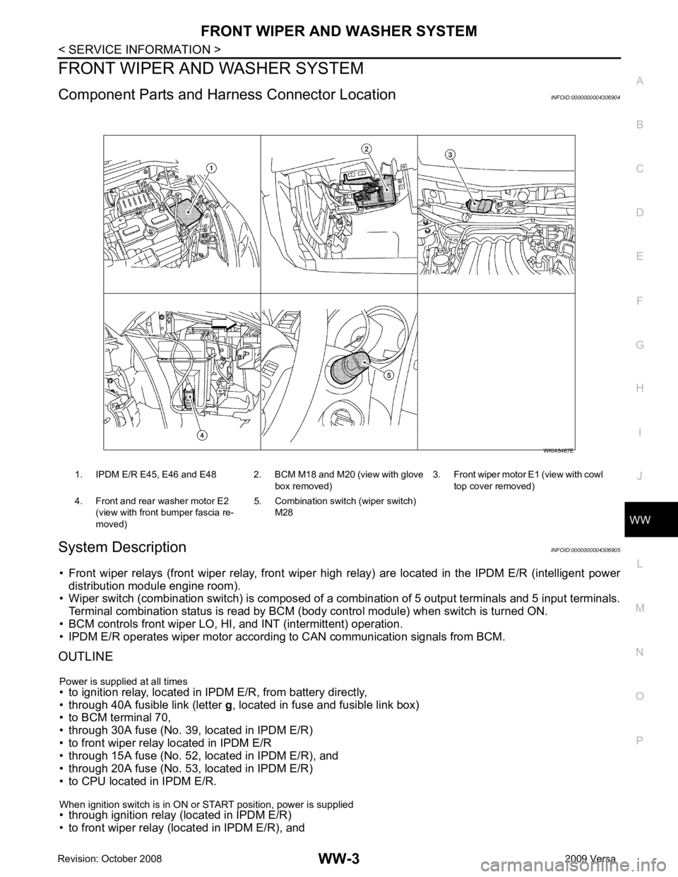
Component Parts and Har ness Connector Location INFOID:0000000004306904
System Description INFOID:0000000004306905
• Front wiper relays (front wiper relay, front wiper hi gh relay) are located in the IPDM E/R (intelligent power
distribution module engine room).
• Wiper switch (combination switch) is composed of a combination of 5 output terminals and 5 input terminals.
Terminal combination status is read by BCM (body control module) when switch is turned ON.
• BCM controls front wiper LO, HI, and INT (intermittent) operation.
• IPDM E/R operates wiper motor accordi ng to CAN communication signals from BCM.
OUTLINE
Power is supplied at all times
• to ignition relay, located in IPDM E/R, from battery directly,
• through 40A fusible link (letter g, located in fuse and fusible link box)
• to BCM terminal 70,
• through 30A fuse (No. 39, located in IPDM E/R)
• to front wiper relay located in IPDM E/R
• through 15A fuse (No. 52, located in IPDM E/R), and
• through 20A fuse (No. 53, located in IPDM E/R)
• to CPU located in IPDM E/R.
When ignition switch is in ON or START position, power is supplied
• through ignition relay (located in IPDM E/R)
• to front wiper relay (located in IPDM E/R), and 1. IPDM E/R E45, E46 and E48 2. BCM M18 and M20 (view with glove
box removed)3. Front wiper motor E1
(view with cowl
top cover removed)
4. Front and rear washer motor E2 (view with front bumper fascia re-
moved) 5. Combination switch (wiper switch)
M28
Page 4297 of 4331

WW
N
O P
AUTO STOP OPERATION
With wiper switch turned OFF, wiper motor will cont inue to operate until wiper arms reach windshield base.
When the wiper arms are not located at base of wi ndshield with wiper switch OFF, ground is supplied
• from IPDM E/R terminal 33
• to front wiper motor terminal 3, in order to continue wiper motor operation at low speed.
When the wiper arms reach base of windshield, fr ont wiper motor terminals 4 and 2 are connected, and
ground is supplied
• to IPDM E/R terminal 38
• through front wiper motor terminals 4 and 2, and
• through grounds E15 and E24.
Then the IPDM E/R sends auto stop operation signal to BCM with CAN communication line.
When the BCM receives auto-stop operation signal, BCM sends wiper stop signal to IPDM E/R with CAN com-
munication line.
IPDM E/R stops wiper motor. Wiper motor wi ll then stop wiper arms at the STOP position.
WASHER OPERATION When the wiper switch is in front wiper washer positi on, BCM detect front wiper washer signal by BCM combi-
nation switch reading function. Refer to BCS-3, " System Description " .
Combination switch power is supplied
• through combination switch terminal 14
• to washer motor terminal 1.
Ground is supplied
• to front washer motor terminal 2
• through combination switch terminal 11, and
• through combination switch terminal 12
• through grounds M57 and M61.
With ground supplied, front washer motor is operated.
When the BCM detects that front washer motor has operated for 0.4 seconds or longer, BCM operates front
wiper motor for low speed.
When the BCM detects washer switch is OFF, low speed operation cycles approximately 2 times and stops.
MIST OPERATION When the wiper switch is turned to the mist positi on, wiper low speed operation cycles once and then stops.
For additional information about wiper operation under th is condition, refer to "LOW SPEED WIPER OPERA-
TION" .
If switch is held in mist posit ion, low speed operation continues.
FAIL-SAFE FUNCTION If an abnormality occurs in CAN communications, IPDM E/ R holds the condition just before fail-safe status is
initiated until ignition switch is turned OFF. (If wipers we re operating in LO just before the initiation of fail-safe
status, they continue to operate in LO until ignition switch is turned OFF.)
COMBINATION SWITCH READING FUNCTION Refer to BCS-3, " System Description " .
CAN Communication System Description INFOID:0000000004306906
Refer to LAN-8, " System Description " .
Page 4299 of 4331
WW
N
O P
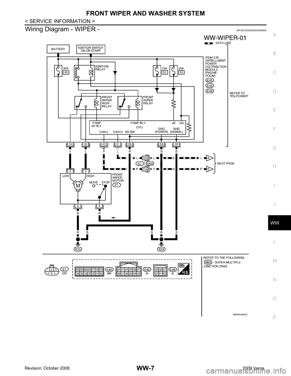
Wiring Diagram - WIPER -
INFOID:0000000004306908
Page 4302 of 4331

Terminal and Reference Value for BCM " .
Terminal and Reference Value for IPDM E/R INFOID:0000000004306910
Refer to PG-24, " Terminal and Reference Value for IPDM E/R " .
How to Proceed with Trouble Diagnosis INFOID:0000000004306911
1. Confirm symptoms and customer complaint.
2. Understand operation description and function description. Refer to WW-3, " System Description " .
3. Perform preliminary check. Refer to WW-10, " Preliminary Check " .
4. Check symptom and repair or replace malfunctioning parts.
5. Does front wiper and washer operate normally ? If YES, GO TO 6. If NO, GO TO 4.
6. Inspection End.
Preliminary Check INFOID:0000000004306912
CHECK POWER SUPPLY AND GROUND CIRCUIT FOR BCM
Refer to BCS-15, " BCM Power Supply and Ground Circuit Inspection "
Item Description CONSULT-III Factory setting
WIPER SPEED SETTING Vehicle speed sensing type wiper control mode can be changed in this mode. ON
×
OFF — ALL SIGNALS Monitors all the signals.
SELECTION FROM MENU Selects items and monitor them. Monitor item Contents
IGN ON SW “ON/OFF” Displays “ignition switch ON (ON)/Other OFF or ACC (OFF)” status as judged from ignition
switch signal.
IGN SW CAN “ON/OFF” Displays “ignition switch ON (ON)/Other OFF or ACC (OFF)” status as judged from CAN com-
munication signal.
FR WIPER HI “ON/OFF” Displays “FRONT WI PER HI (ON)/Other (OFF)” status as judged from wiper switch signal.
FR WIPER LOW “ON/OFF” Displays “FRONT WIPER LOW (ON)/Other (OFF)” status as judged from wiper switch signal.
Page 4303 of 4331

WW
N
O P
NOTE: This item is displayed, but cannot be monitored.
ACTIVE TEST
Display Item List
CONSULT-III Function (IPDM E/R) INFOID:0000000004306914
CONSULT-III can display each diagnostic item using the diagnostic test modes shown following.
DATA MONITOR
All Signals, Main Signals, Selection From Menu
NOTE: FR WIPER INT “ON/OFF” Displays “FRONT WIPER INT (ON)/Other
(OFF)” status as judged from wiper switch signal.
FR WASHER SW “ON/OFF” Displays “FRONT WASHER Switch
(ON)/Other (OFF)” status as judged from wiper switch sig-
nal.
INT VOLUME “1 - 7” Displays intermittent operation dial position setting (1 - 7) as judged from wiper switch signal.
FR WIPER STOP “ON/OFF” Displays “Stopped (ON)/Operati ng (OFF)” status as judged from auto-stop signal.
VEHICLE SPEED “km/h” Displays vehicle speed stat us as judged from vehicle speed signal.
RR WIPER ON “ON/OFF” Displays “REAR WIPER (ON)/Other (O FF)” status as judged from wiper switch signal.
RR WIPER INT “ON/OFF” Displays “REAR WIPER INT (ON)/Other (OFF)” status as judged from wiper switch signal.
RR WASHER SW “ON/OFF” Displays “FRONT WASHER Switch
(ON)/Other (OFF)” status as judged from wiper switch sig-
nal.
RR WIPER STOP “ON/OFF” Displays “Stopp ed (ON)/Operating (OFF)” status as judged from auto-stop switch 1.
RR WIPER STP2 “ON/OFF” Displays “Stopp ed (ON)/Operating (OFF)” status as judged from auto-stop switch 2.
H/L WASH SW NOTE
“OFF” —
Monitor item Contents Test item Display on CONSULT-III screen Description
Front wiper LO output FR WIPER (LO) Front LO wiper can be operated by any ON-OFF operation.
Front wiper HI output FR WIPER (HI) Front HI wiper can be operated by any ON-OFF operation.
Front wiper INT output FR WIPER (INT) Front INT wiper can be operated by any ON-OFF operation.
Rear wiper output RR WIPER Rear wiper can be operated by any ON-OFF operation. IPDM E/R diagnostic Mode Description
SELF-DIAG RESULTS Displays IPDM E/R self-diagnosis results.
DATA MONITOR Displays IPDM E/R input/output data in real time.
CAN DIAG SUPPORT MNTR The result of transmit/receive diagnosis of CAN communication can be read. ACTIVE TEST Operation of electrical loads can be checked by sending drive signal to them. ALL SIGNALS Monitors all items.
MAIN SIGNALS Monitor the predetermined item.
SELECTION FROM MENU Selects items and monitors them. Item name
CONSULT-III
screen display Display or unit Monitor item selection
Description
ALL
SIGNALS MAIN
SIGNALS SELECTION
FROM MENU
FR wiper request FR WIP REQ STOP/1LOW/
LOW/HI × × ×
Signal status input from BCM
Wiper auto stop WIP AUTO STOP ACT P/STOP P × × ×Output status of IPDM E/R
Wiper protection WIP PROT OFF/BLOCK × × ×Control status of IPDM E/R
Page 4304 of 4331
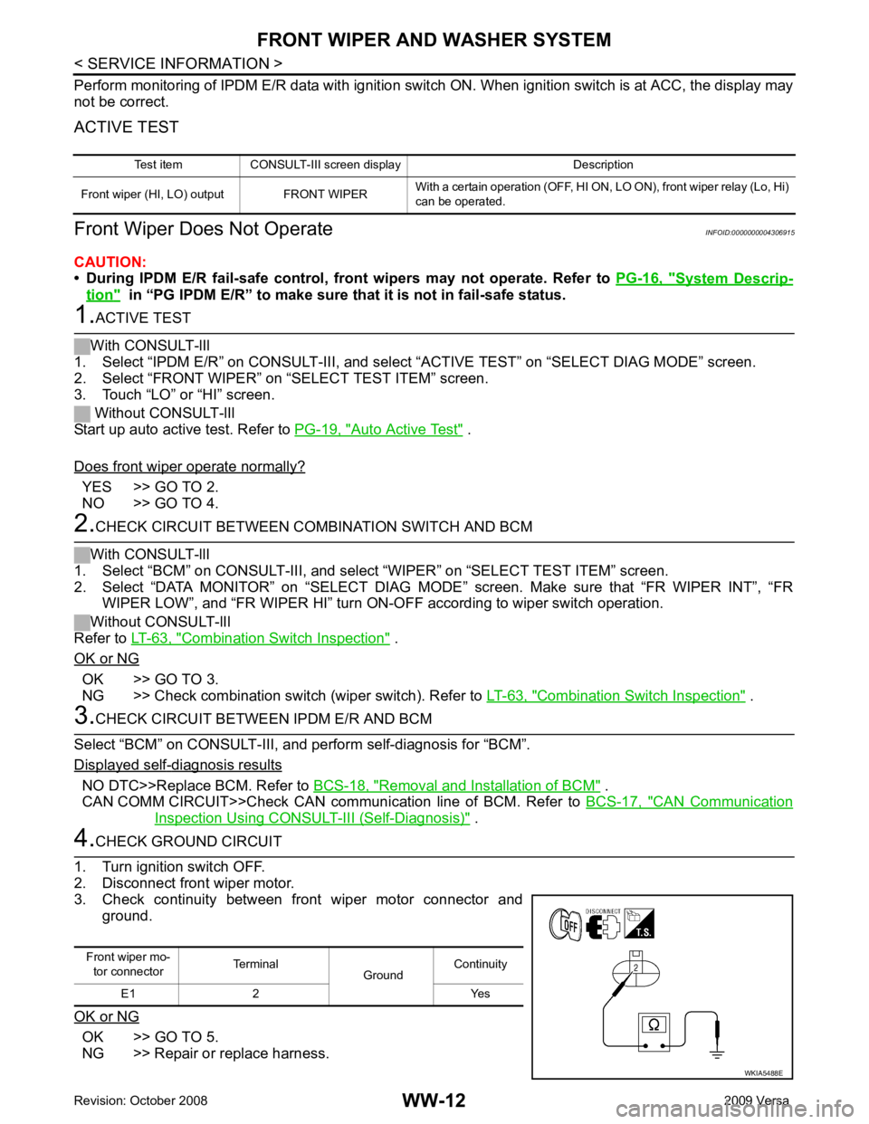
System Descrip-
tion " in “PG IPDM E/R” to make sure
that it is not in fail-safe status. Auto Active Test " .
Does front wiper operate normally? YES >> GO TO 2.
NO >> GO TO 4. Combination Switch Inspection " .
OK or NG OK >> GO TO 3.
NG >> Check combination switch (wiper switch). Refer to LT-63, " Combination Switch Inspection " .
- diagnosis results
NO DTC>>Replace BCM. Refer to
BCS-18, " Removal and Installation of BCM " .
CAN COMM CIRCUIT>>Check CAN communi cation line of BCM. Refer to BCS-17, " CAN Communication
Inspection Using CONSULT-III (Self-Diagnosis) " .
OK >> GO TO 5.
NG >> Repair or replace harness. Test item CONSULT-III screen display Description
Front wiper (HI, LO) output FRONT WIPER With a certain operation (OFF, HI ON,
LO ON), front wiper relay (Lo, Hi)
can be operated. Front wiper mo-
tor connector Terminal
GroundContinuity
E1 2 Yes
Page 4305 of 4331
WW
N
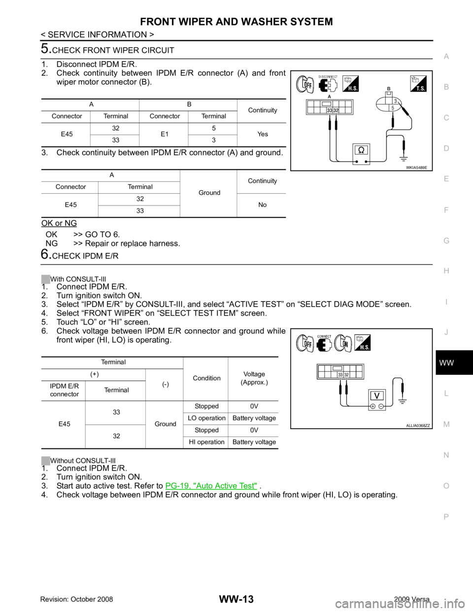
O P OK >> GO TO 6.
NG >> Repair or replace harness. Auto Active Test " .
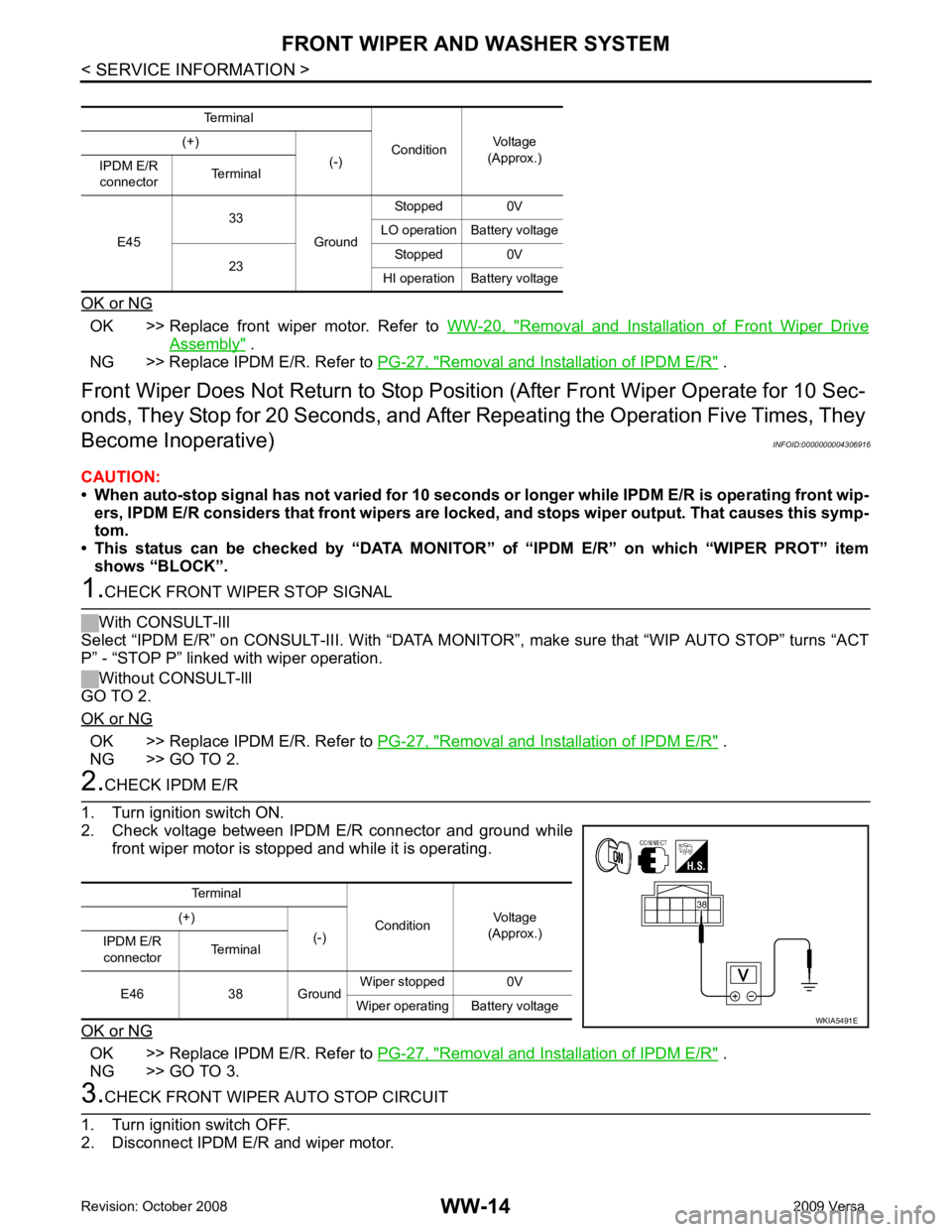
4. Check voltage between IPDM E/R connector and gr ound while front wiper (HI, LO) is operating.
A B
Continuity
Connector Terminal Connector Terminal
E45 32
E1 5
Yes
33 3
A GroundContinuity
Connector Terminal
E45 32
No
33
Page 4306 of 4331
OK >> Replace front wiper motor. Refer to
WW-20, " Removal and Installation of Front Wiper Drive
Assembly " .
NG >> Replace IPDM E/R. Refer to PG-27, " Removal and Installation of IPDM E/R " .
Front Wiper Does Not Return to Stop Positi on (After Front Wiper Operate for 10 Sec-
onds, They Stop for 20 Second s, and After Repeating the Operation Five Times, They
Become Inoperative) INFOID:0000000004306916
CAUTION:
• When auto-stop signal has not varied for 10 seconds or longer while IPDM E/R is operating front wip-
ers, IPDM E/R considers that front wipers are locked, and stops wiper output. That causes this symp-
tom.
• This status can be checked by “DATA MONITOR” of “IPDM E/R” on which “WIPER PROT” item
shows “BLOCK”. OK >> Replace IPDM E/R. Refer to
PG-27, " Removal and Installation of IPDM E/R " .
NG >> GO TO 2. OK >> Replace IPDM E/R. Refer to
PG-27, " Removal and Installation of IPDM E/R " .
NG >> GO TO 3. Terminal
ConditionVoltage
(Approx.)
(+)
(-)
IPDM E/R
connector Terminal
E46 38 Ground Wiper stopped 0V
Wiper operating Battery voltage
Page 4307 of 4331
WW
N
O P
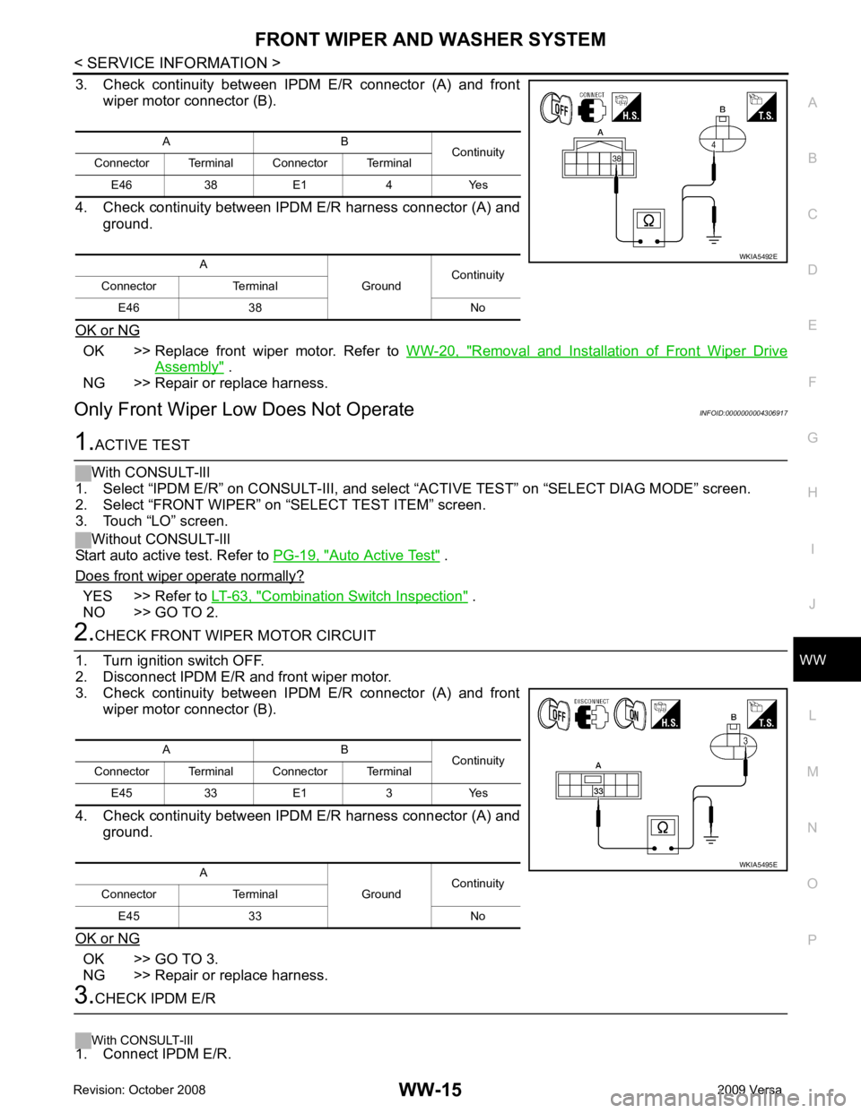
3. Check continuity between IPDM E/R connector (A) and front
wiper motor connector (B).
4. Check continuity between IPDM E/R harness connector (A) and ground.
OK or NG OK >> Replace front wiper motor. Refer to
WW-20, " Removal and Installation of Front Wiper Drive
Assembly " .
NG >> Repair or replace harness.
Only Front Wiper Low Does Not Operate INFOID:0000000004306917Auto Active Test " .
Does front wiper operate normally? YES >> Refer to
LT-63, " Combination Switch Inspection " .
NO >> GO TO 2. OK >> GO TO 3.
NG >> Repair or replace harness.