NISSAN TIIDA 2009 Service Repair Manual
Manufacturer: NISSAN, Model Year: 2009, Model line: TIIDA, Model: NISSAN TIIDA 2009Pages: 4331, PDF Size: 58.04 MB
Page 4071 of 4331
PS
N
O P
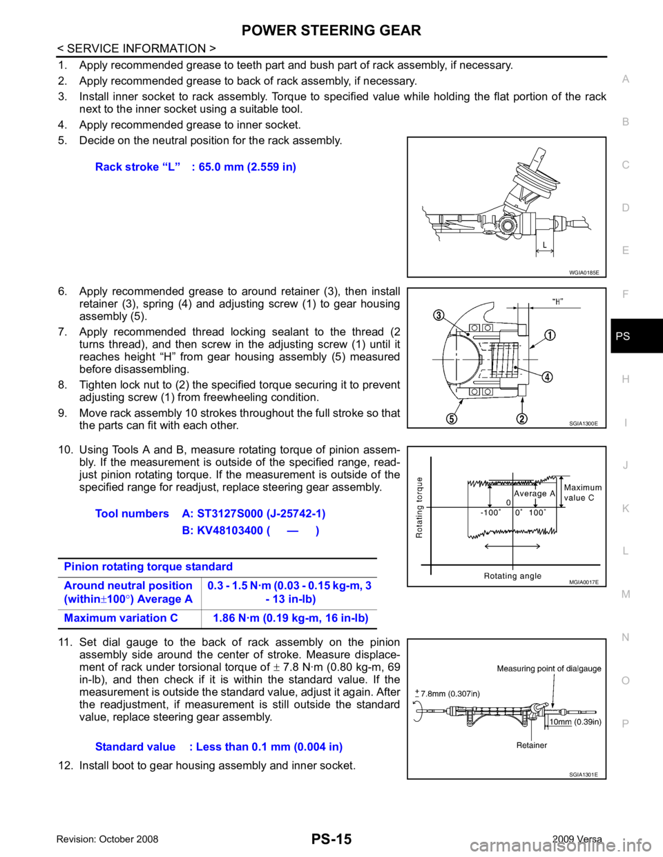
1. Apply recommended grease to teeth part and bush part of rack assembly, if necessary.
2. Apply recommended grease to back of rack assembly, if necessary.
3. Install inner socket to rack assembly. Torque to specified value while holding the flat portion of the rack next to the inner socket using a suitable tool.
4. Apply recommended grease to inner socket.
5. Decide on the neutral position for the rack assembly.
6. Apply recommended grease to around retainer (3), then install retainer (3), spring (4) and adjusting screw (1) to gear housing
assembly (5).
7. Apply recommended thread locking sealant to the thread (2 turns thread), and then screw in the adjusting screw (1) until it
reaches height “H” from gear housing assembly (5) measured
before disassembling.
8. Tighten lock nut to (2) the specified torque securing it to prevent adjusting screw (1) from freewheeling condition.
9. Move rack assembly 10 strokes throughout the full stroke so that the parts can fit with each other.
10. Using Tools A and B, measure rotating torque of pinion assem- bly. If the measurement is outside of the specified range, read-
just pinion rotating torque. If the measurement is outside of the
specified range for readjust, replace steering gear assembly.
11. Set dial gauge to the back of rack assembly on the pinion assembly side around the center of stroke. Measure displace-
ment of rack under torsional torque of ± 7.8 N·m (0.80 kg-m, 69
in-lb), and then check if it is within the standard value. If the
measurement is outside the standard value, adjust it again. After
the readjustment, if measurement is still outside the standard
value, replace steering gear assembly.
12. Install boot to gear housing assembly and inner socket. Rack stroke “L” : 65.0 mm (2.559 in)
Page 4072 of 4331
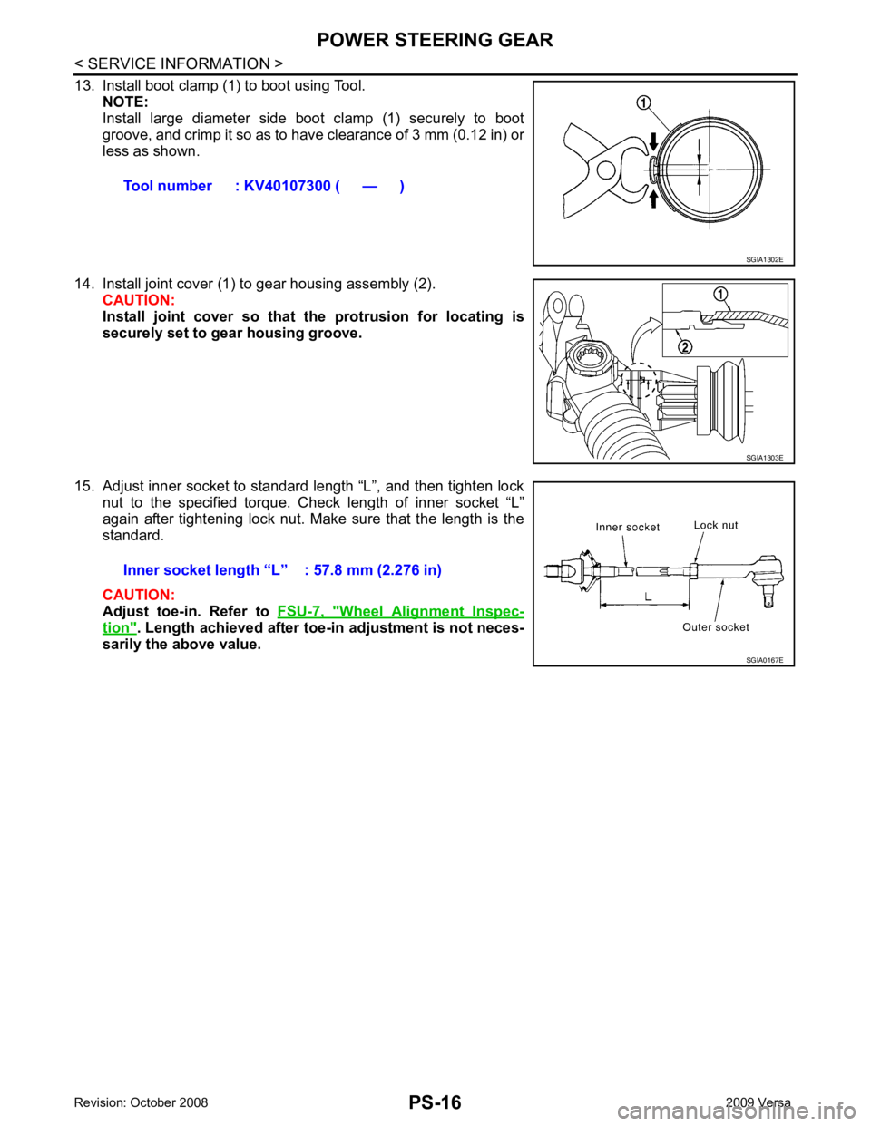
Wheel Alignment Inspec-
tion " . Length achieved after toe-in adjustment is not neces-
sarily the above value. Tool number : KV40107300 ( — ) SGIA1303E
Page 4073 of 4331
SERVICE DATA AND SPECIFICATIONS (SDS)
PS-17
< SERVICE INFORMATION >
C
D E
F
H I
J
K L
M A
B PS
N
O
P
SERVICE DATA AND SPECIFICATIONS (SDS)
Steering Wheel INFOID:0000000004305936
Steering Angle INFOID:0000000004305937
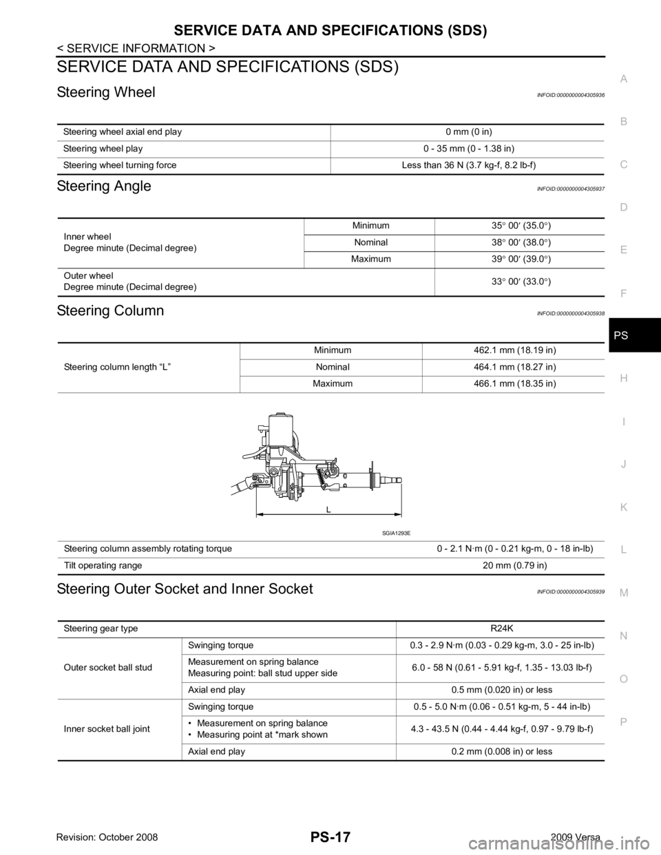
Steering Column INFOID:0000000004305938
Steering Outer Socket and Inner Socket INFOID:0000000004305939
Steering wheel axial end play 0 mm (0 in)
Steering wheel play 0 - 35 mm (0 - 1.38 in)
Steering wheel turning force Less than 36 N (3.7 kg-f, 8.2 lb-f) Inner wheel
Degree minute (Decimal degree) Minimum 35
° 00 ′ (35.0 °)
Nominal 38 ° 00 ′ (38.0 °)
Maximum 39 ° 00 ′ (39.0 °)
Outer wheel
Degree minute (Decimal degree) 33
° 00 ′ (33.0 °) Steering column length “L”
Minimum 462.1 mm (18.19 in)
Nominal 464.1 mm (18.27 in)
Maximum 466.1 mm (18.35 in)
Steering column assembly rotating torque 0 - 2.1 N·m (0 - 0.21 kg-m, 0 - 18 in-lb)
Tilt operating range 20 mm (0.79 in)SGIA1293E
Steering gear type R24K
Outer socket ball stud Swinging torque 0.3 - 2.9 N·m (0.03 - 0.29 kg-m, 3.0 - 25 in-lb)
Measurement on spring balance
Measuring point: ball stud upper side 6.0 - 58 N (0.61 - 5.91 kg-f, 1.35 - 13.03 lb-f)
Axial end play 0.5 mm (0.020 in) or less
Inner socket ball joint Swinging torque 0.5 - 5.0 N·m (0.06 - 0.51 kg-m, 5 - 44 in-lb)
• Measurement on spring balance
• Measuring point at *mark shown 4.3 - 43.5 N (0.44 - 4.44 kg-f, 0.97 - 9.79 lb-f)
Axial end play 0.2 mm (0.008 in) or less
Page 4074 of 4331
PS-18< SERVICE INFORMATION >
SERVICE DATA AND SPECIFICATIONS (SDS)
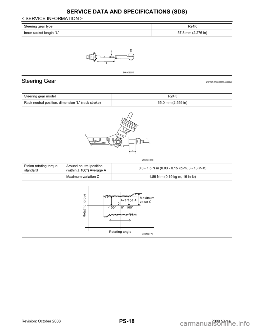
Steering Gear INFOID:0000000004305940
Inner socket length “L”
57.8 mm (2.276 in)
Steering gear type
R24KSGIA0950E
Steering gear model R24K
Rack neutral position, dimension “L ” (rack stroke) 65. 0 mm (2.559 in)
Pinion rotating torque
standard Around neutral position
(within ± 100 °) Average A 0.3 - 1.5 N·m (0.03 - 0.15 kg-m, 3 - 13 in-lb)
Maximum variation C 1.86 N· m (0.19 kg-m, 16 in-lb) WGIA0185E
MGIA0017E
Page 4075 of 4331

RAX
N
O P
CONTENTS
REAR AXLE
SERVICE INFORMATION .. ..........................2
PRECAUTIONS .............................................. .....2
Precaution for Supplemental Restraint System
(SRS) "AIR BAG" and "SEAT BELT PRE-TEN-
SIONER" ............................................................. ......
2
Precaution Necessary fo r Steering Wheel Rota-
tion After Battery Disconnect ............................... ......
2
PREPARATION .............................................. .....3
Commercial Service Tool .................................... ......3 NOISE, VIBRATION AND HARSHNESS
(NVH) TROUBLESHOOTING ............................ 4
NVH Troubleshooting Chart ................................ .....4
WHEEL HUB ...................................................... 5
On-Vehicle Inspection and Service ..................... .....5
Removal and Installation ..................................... .....5
SERVICE DATA AND SPECIFICATIONS
(SDS) .................................................................. 7
Wheel Bearing ..................................................... .....7
Page 4076 of 4331
Page 4077 of 4331
PREPARATION
RAX-3
< SERVICE INFORMATION >
C
E F
G H
I
J
K L
M A
B RAX
N
O P
PREPARATION
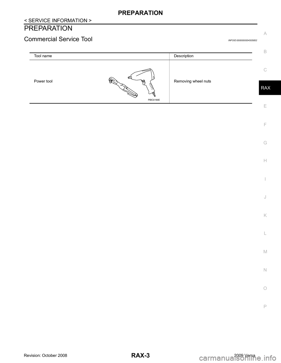
Commercial Service Tool INFOID:0000000004305852
Tool name Description
Power tool Removing wheel nuts PBIC0190E
Page 4078 of 4331
—
RAX-5
RSU-5, "
NVH Troubleshooting Chart
"
WT-5, "
NVH Troubleshooting Chart
"
WT-5, "
NVH Troubleshooting Chart
"
BR-5, "
NVH Troubleshooting Chart
"
PS-5, "
NVH Troubleshooting Chart
" Possible cause and SUSPECTED PARTS
Improper installation, looseness
Parts interference
Wheel bearing damage
REAR SUSPENSION
TIRES
ROAD WHEEL
BRAKES
STEERING
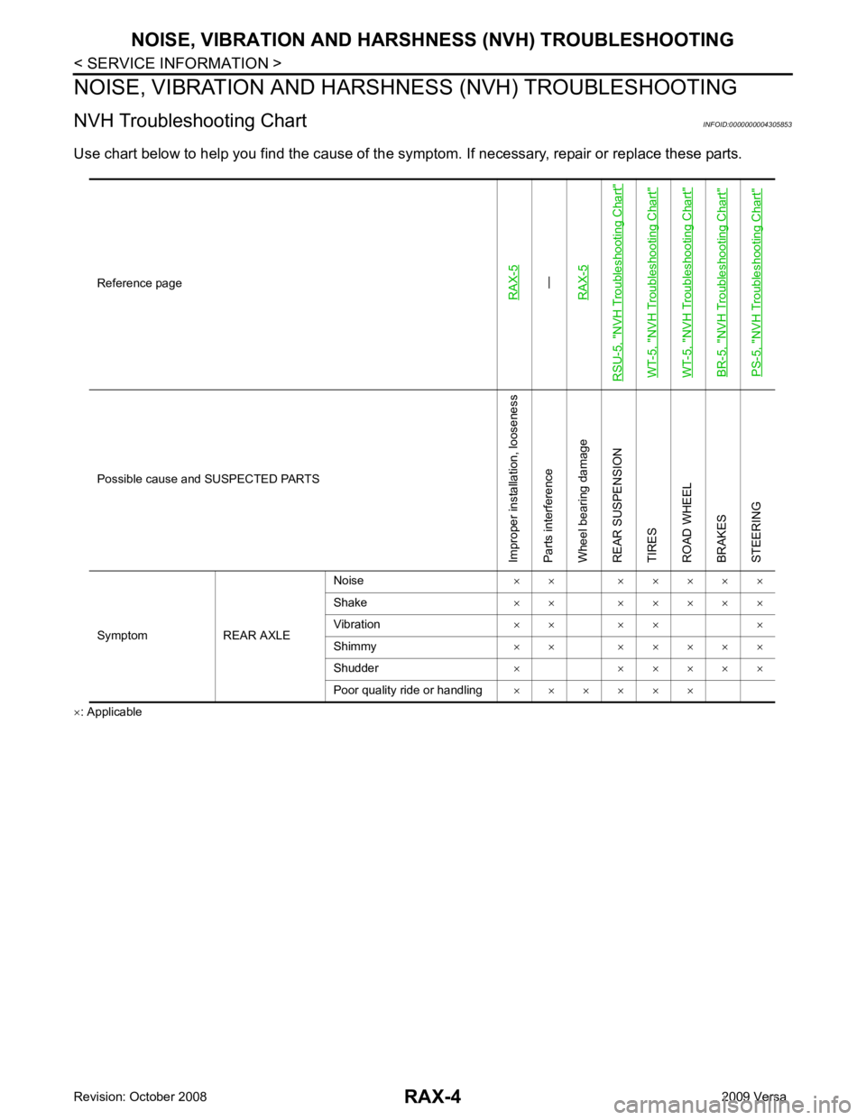
Symptom REAR AXLE Noise
× × × × × × ×
Shake × × × × × × ×
Vibration × × × × ×
Shimmy × × × × × × ×
Shudder × × × × × ×
Poor quality ride or handling × × × × × ×
Page 4079 of 4331
WHEEL HUB
RAX-5
< SERVICE INFORMATION >
C
E F
G H
I
J
K L
M A
B RAX
N
O P
WHEEL HUB
On-Vehicle Inspection and Service INFOID:0000000004305854
• Check the axle and suspension parts for excessive play, wear, or damage.
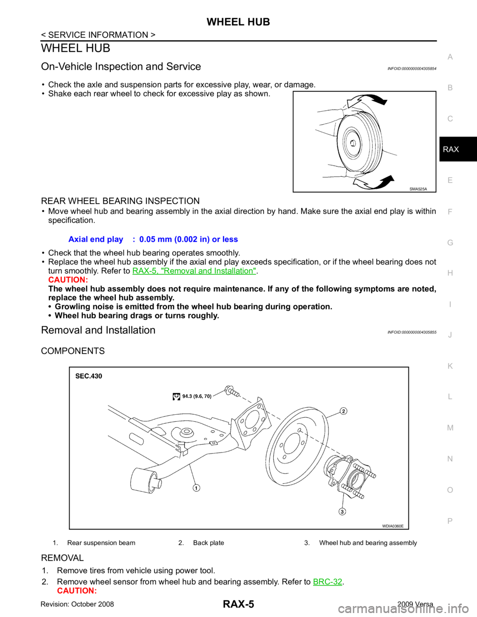
• Shake each rear wheel to check for excessive play as shown.
REAR WHEEL BEARING INSPECTION • Move wheel hub and bearing assembly in the axial direction by hand. Make sure the axial end play is within specification.
• Check that the wheel hub bearing operates smoothly.
• Replace the wheel hub assembly if the axial end play e xceeds specification, or if the wheel bearing does not
turn smoothly. Refer to RAX-5, " Removal and Installation " .
CAUTION:
The wheel hub assembly does not requ ire maintenance. If any of the following symptoms are noted,
replace the wheel hub assembly.
• Growling noise is emitted from th e wheel hub bearing during operation.
• Wheel hub bearing dr ags or turns roughly.
Removal and Installation INFOID:0000000004305855
COMPONENTS
REMOVAL 1. Remove tires from vehicle using power tool.
2. Remove wheel sensor from wheel hub and bearing assembly. Refer to BRC-32 .
CAUTION: SMA525A
Axial end play : 0.05 mm (0.002 in) or less
1. Rear suspension beam 2. Back plate 3. Wheel hub and bearing assembly WDIA0360E
Page 4080 of 4331
Removal and Installation of Drum Brake Assembly " .
4. Remove wheel hub and bearing assembly bolts, and then remove wheel hub and bearing assembly from vehicle.
5. If necessary remove back plate, following procedure. 1. Remove parking brake rear cable from back plate. Refer to PB-6, " Removal and Installation " .
2. Separate brake tube from wheel cylinder. Refer to BR-12, " Rear Brake Tube and Hose " .
INSPECTION AFTER REMOVAL
Check for any deformity, cracks, or other damage on the wheel hub assembly, replace if necessary.
CAUTION:
The wheel hub assembly does not require maintenance. If any of the following symptoms are noted,
replace the wheel hub assembly.
• Growling noise is emitted from the wheel hub bearing during operation.
• Wheel hub bearing drags or turns roughly.
INSTALLATION
Installation is in the reverse order of removal.