NISSAN TIIDA 2009 Service Repair Manual
Manufacturer: NISSAN, Model Year: 2009, Model line: TIIDA, Model: NISSAN TIIDA 2009Pages: 4331, PDF Size: 58.04 MB
Page 4101 of 4331
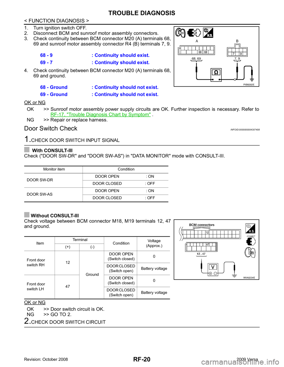
OK >> Sunroof motor assembly power supply circuits
are OK. Further inspection is necessary. Refer to
RF-17, " Trouble Diagnosis Chart by Symptom " .
NG >> Repair or replace harness.
Door Switch Check INFOID:0000000004307408OK >> Door switch circuit is OK.
NG >> GO TO 2. Item
Terminal
ConditionVoltage
(Approx.)
(+) (-)
Front door
switch RH 12
Ground DOOR OPEN
(Switch closed) 0
DOOR CLOSED (Switch open) Battery voltage
Front door
switch LH 47 DOOR OPEN
(Switch closed) 0
DOOR CLOSED (Switch open) Battery voltage
Page 4102 of 4331
RF
N
O P
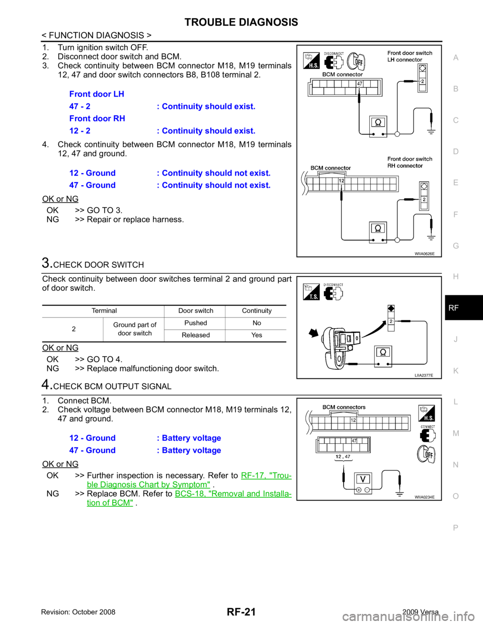
1. Turn ignition switch OFF.
2. Disconnect door switch and BCM.
3. Check continuity between BCM connector M18, M19 terminals
12, 47 and door switch connectors B8, B108 terminal 2.
4. Check continuity between BCM connector M18, M19 terminals 12, 47 and ground.
OK or NG OK >> GO TO 3.
NG >> Repair or replace harness. OK >> GO TO 4.
NG >> Replace malfunctioning door switch. OK >> Further inspection is necessary. Refer to
RF-17, " Trou-
ble Diagnosis Chart by Symptom " .
NG >> Replace BCM. Refer to BCS-18, " Removal and Installa-
tion of BCM " .
Front door LH
47 - 2 : Continuity should exist.
Front door RH
12 - 2 : Continuity should exist.
12 - Ground : Continuity should not exist.
47 - Ground : Continuity should not exist.
Page 4103 of 4331
Page 4104 of 4331
RF
N
O P
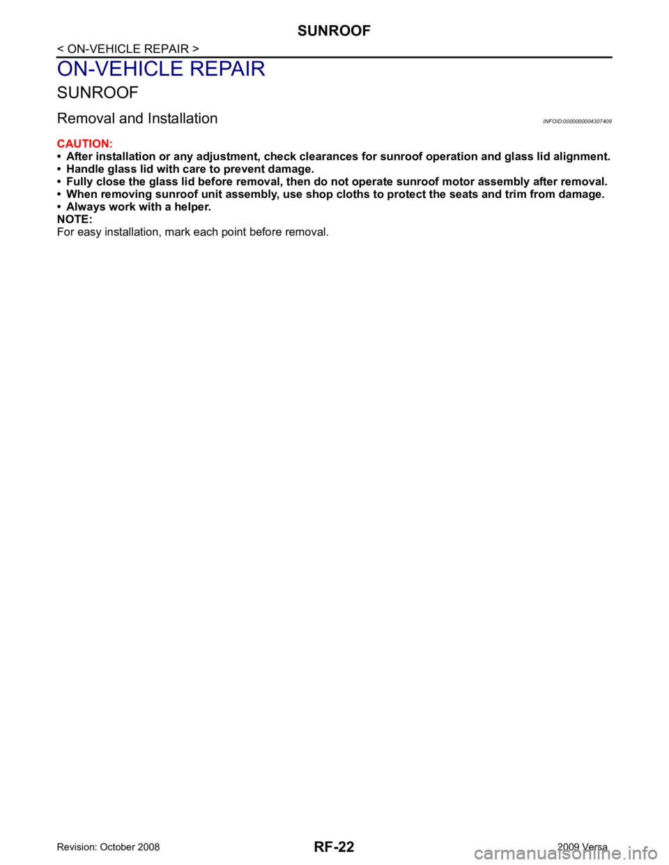
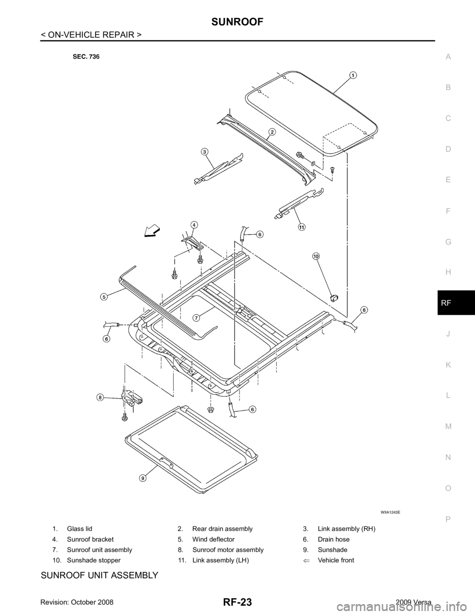
SUNROOF UNIT ASSEMBLY 1. Glass lid 2. Rear drain assembly 3. Link assembly (RH)
4. Sunroof bracket 5. Wind deflector 6. Drain hose
7. Sunroof unit assembly 8. Sunroof motor assembly 9. Sunshade
10. Sunshade stopper 11. Link assembly (LH) ⇐Vehicle front
Page 4105 of 4331
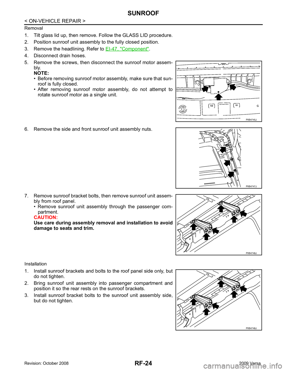
Component " .
4. Disconnect drain hoses.
5. Remove the screws, then disconnect the sunroof motor assem- bly.
NOTE:
• Before removing sunroof motor assembly, make sure that sun- roof is fully closed.
• After removing sunroof motor assembly, do not attempt to
rotate sunroof motor as a single unit.
6. Remove the side and front sunroof unit assembly nuts.
7. Remove sunroof bracket bolts, then remove sunroof unit assem- bly from roof panel.
• Remove sunroof unit assembly through the passenger com-
partment.
CAUTION:
Use care during assembly removal and installation to avoid
damage to seats and trim.
Installation
1. Install sunroof brackets and bolts to the roof panel side only, but do not tighten.
2. Bring sunroof unit assembly into passenger compartment and position it so the rear rests on the sunroof brackets.
3. Install sunroof bracket bolts to the sunroof unit assembly side, but do not tighten. PIIB4747J
PIIB4748J
Page 4106 of 4331
SUNROOF
RF-25
< ON-VEHICLE REPAIR >
C
D E
F
G H
J
K L
M A
B RF
N
O P
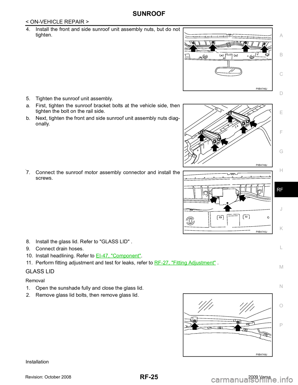
4. Install the front and side sunroof unit assembly nuts, but do not
tighten.
5. Tighten the sunroof unit assembly.
a. First, tighten the sunroof bracket bolts at the vehicle side, then tighten the bolt on the rail side.
b. Next, tighten the front and side sunroof unit assembly nuts diag- onally.
6. 7. Connect the sunroof motor assembly connector and install the
screws.
8. Install the glass lid. Refer to "GLASS LID" .
9. Connect drain hoses.
10. Install headlining. Refer to EI-47, " Component " .
11. Perform fitting adjustment and test for leaks, refer to RF-27, " Fitting Adjustment " .
GLASS LID
Removal 1. Open the sunshade fully and close the glass lid.
2. Remove glass lid bolts, then remove glass lid.
Installation PIIB4746J
PIIB4748J
PIIB4745J
PIIB4749J
Page 4107 of 4331
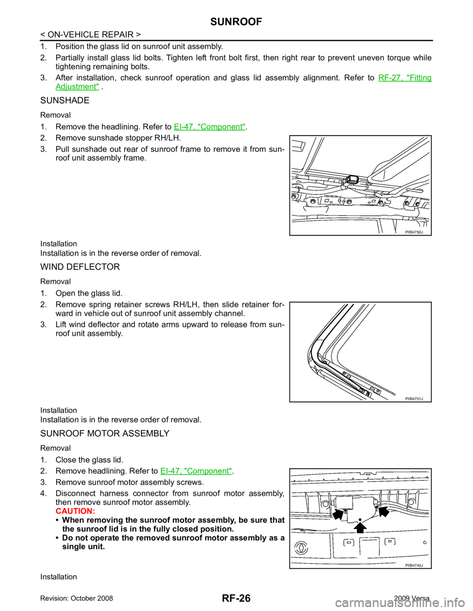
Fitting
Adjustment " .
SUNSHADE
Removal
1. Remove the headlining. Refer to EI-47, " Component " .
2. Remove sunshade stopper RH/LH.
3. Pull sunshade out rear of sunroof frame to remove it from sun- roof unit assembly frame.
Installation
Installation is in the reverse order of removal.
WIND DEFLECTOR
Removal
1. Open the glass lid.
2. Remove spring retainer screws RH/LH, then slide retainer for- ward in vehicle out of sunroof unit assembly channel.
3. Lift wind deflector and rotate arms upward to release from sun- roof unit assembly.
Installation
Installation is in the reverse order of removal.
SUNROOF MOTOR ASSEMBLY
Removal
1. Close the glass lid.
2. Remove headlining. Refer to EI-47, " Component " .
3. Remove sunroof motor assembly screws.
4. Disconnect harness connector from sunroof motor assembly, then remove sunroof motor assembly.
CAUTION:
• When removing the sunroof motor assembly, be sure that
the sunroof lid is in th e fully closed position.
• Do not operate the removed sunroof motor assembly as a
single unit.
Installation PIIB4745J
Page 4108 of 4331
RF
N
O P
CAUTION:
• Before installing the sunroof motor assembly, be su re the link assembly is in the symmetrical and
fully closed position.
• Align the link notch with the hole of the guide track (fully closed: RH and LH).
1. Place the sunroof motor assembly flat onto the sunroof unit assembly surface.
2. Laterally move the assembly little by little so that the gear is completely engaged into the wire and there is no gap between the sunroof unit assembly and sunroof motor assembly.
3. Install the sunroof motor assembly screws, then connect the harness connector.
4. After installing, perform the initialization procedure. Refer to RF-11, " System Description " .
LINK ASSEMBLY
Removal 1. Remove sunroof unit assembly. Follow the SUNROOF UNIT ASSEMBLY procedure.
2. Remove screws, then remove rear drain assembly.
3. Remove sunroof motor assembly. Follo w the SUNROOF MOTOR ASSEMBLY procedure.
4. Remove link assembly from t he rear end of the sunroof frame.
Installation Installation is in the reverse order of removal.
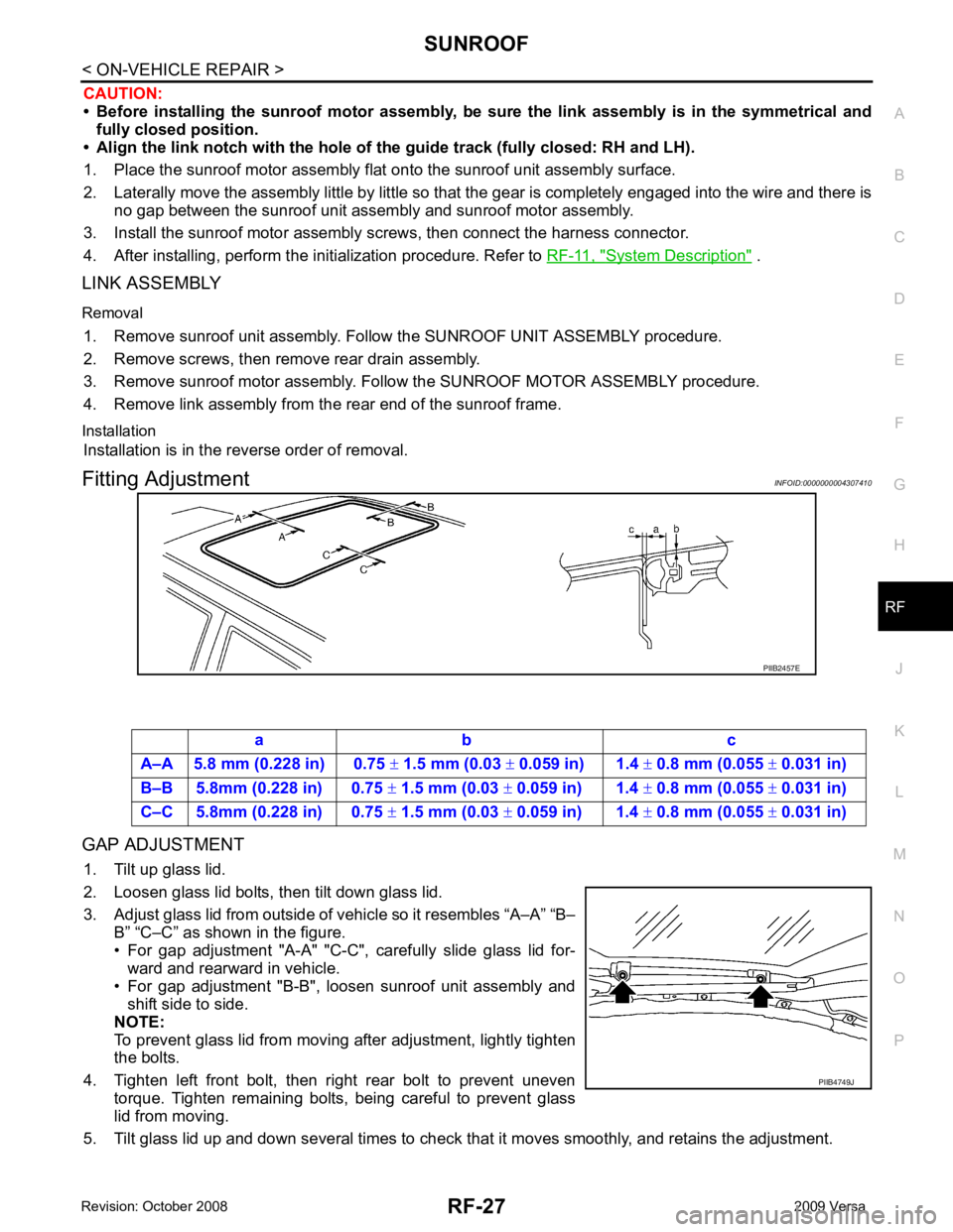
Fitting Adjustment INFOID:0000000004307410
GAP ADJUSTMENT 1. Tilt up glass lid.
2. Loosen glass lid bolts, then tilt down glass lid.
3. Adjust glass lid from outside of vehicle so it resembles “A–A” “B– B” “C–C” as shown in the figure.
• For gap adjustment "A-A" "C-C", carefully slide glass lid for- ward and rearward in vehicle.
• For gap adjustment "B-B", loosen sunroof unit assembly and
shift side to side.
NOTE:
To prevent glass lid from moving after adjustment, lightly tighten
the bolts.
4. Tighten left front bolt, then right rear bolt to prevent uneven torque. Tighten remaining bolts, being careful to prevent glass
lid from moving.
5. Tilt glass lid up and down several times to check that it moves smoothly, and retains the adjustment.
Page 4109 of 4331
RF-28< ON-VEHICLE REPAIR >
SUNROOF
HEIGHT ADJUSTMENT
1. Tilt up glass lid.
2. Loosen glass lid bolts, then tilt down glass lid.
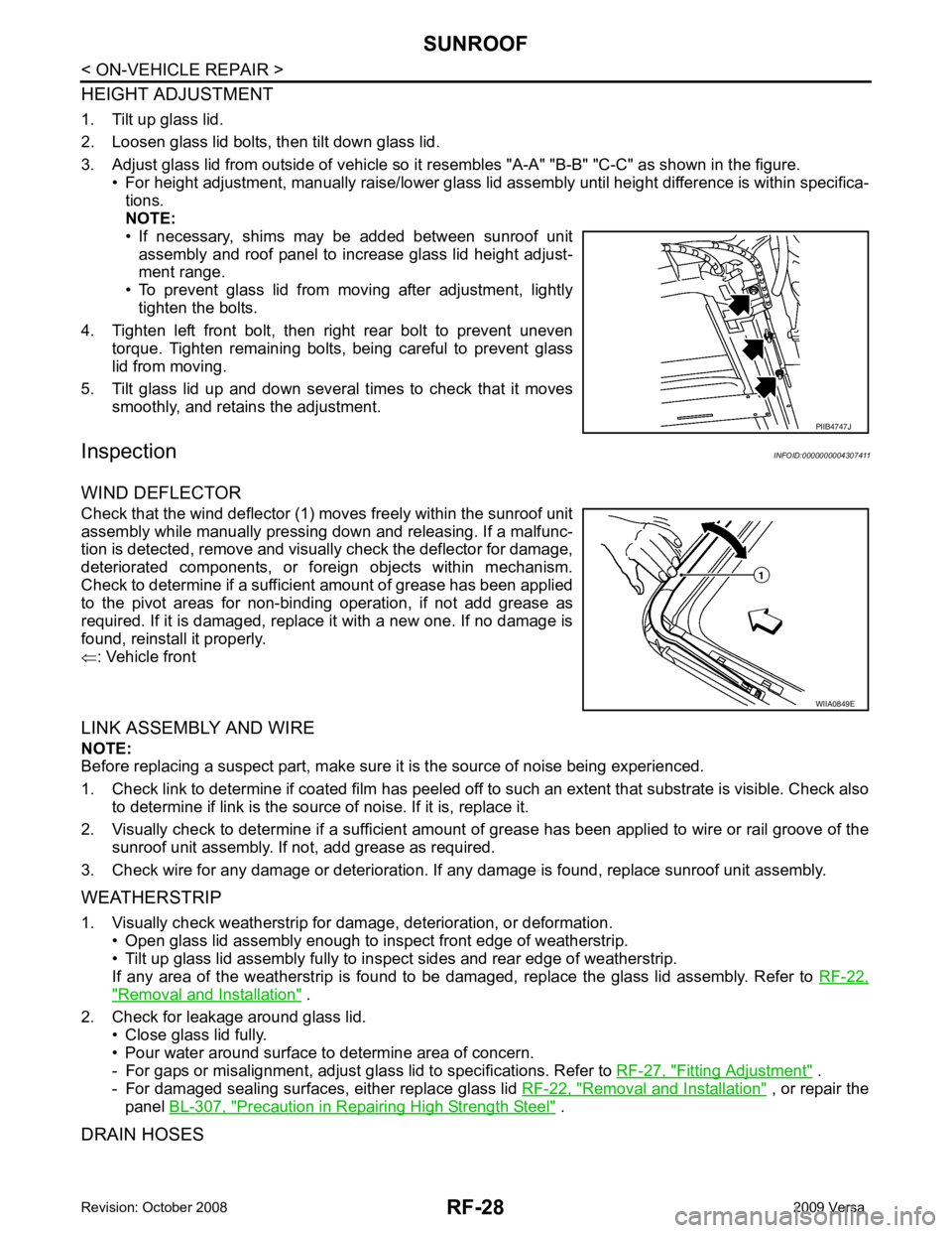
3. Adjust glass lid from outside of vehicle so it resembles "A-A" "B-B" "C-C" as shown in the figure.
• For height adjustment, manually raise/lower glass lid assembly until height difference is within specifica-
tions.
NOTE:
• If necessary, shims may be added between sunroof unit
assembly and roof panel to increase glass lid height adjust-
ment range.
• To prevent glass lid from moving after adjustment, lightly
tighten the bolts.
4. Tighten left front bolt, then right rear bolt to prevent uneven torque. Tighten remaining bolts, being careful to prevent glass
lid from moving.
5. Tilt glass lid up and down several times to check that it moves smoothly, and retains the adjustment.
Inspection INFOID:0000000004307411
WIND DEFLECTOR
Check that the wind deflector (1) moves freely within the sunroof unit
assembly while manually pressing down and releasing. If a malfunc-
tion is detected, remove and visually check the deflector for damage,
deteriorated components, or foreign objects within mechanism.
Check to determine if a sufficient amount of grease has been applied
to the pivot areas for non-binding operation, if not add grease as
required. If it is damaged, replace it with a new one. If no damage is
found, reinstall it properly.
⇐ : Vehicle front
LINK ASSEMBLY AND WIRE
NOTE:
Before replacing a suspect part, make sure it is the source of noise being experienced.
1. Check link to determine if coated film has peeled off to such an extent that substrate is visible. Check also
to determine if link is the source of noise. If it is, replace it.
2. Visually check to determine if a sufficient amount of grease has been applied to wire or rail groove of the
sunroof unit assembly. If not, add grease as required.
3. Check wire for any damage or deterioration. If any damage is found, replace sunroof unit assembly.
WEATHERSTRIP
1. Visually check weatherstrip for dam age, deterioration, or deformation.
• Open glass lid assembly enough to inspect front edge of weatherstrip.
• Tilt up glass lid assembly fully to in spect sides and rear edge of weatherstrip.
If any area of the weatherstrip is found to be damaged, replace the glass lid assembly. Refer to RF-22," Removal and Installation " .
2. Check for leakage around glass lid. • Close glass lid fully.
• Pour water around surface to determine area of concern.
- For gaps or misalignment, adjust glass lid to specifications. Refer to RF-27, " Fitting Adjustment " .
- For damaged sealing surfaces, either replace glass lid RF-22, " Removal and Installation " , or repair the
panel BL-307, " Precaution in Repairing High Strength Steel " .
DRAIN HOSES PIIB4747J
WIIA0849E
Page 4110 of 4331
RF
N
O P
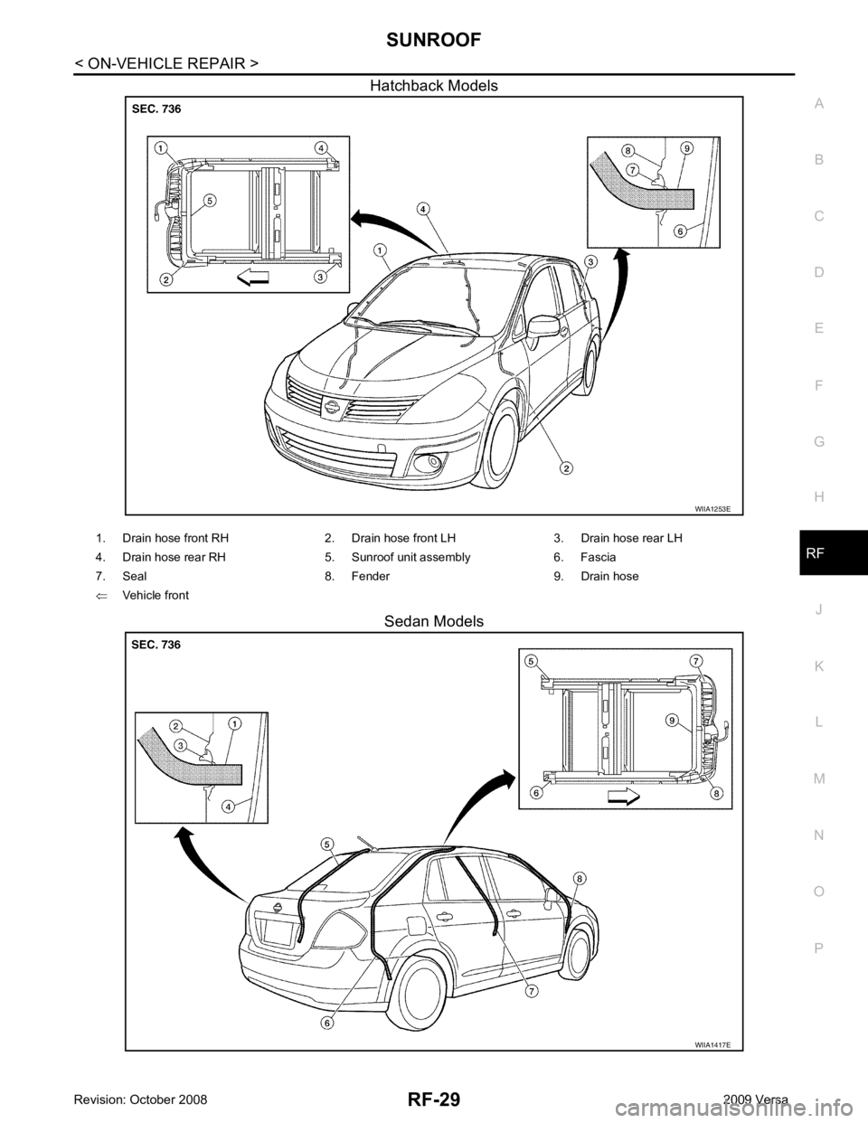
Hatchback Models
Sedan Models