Panel NISSAN TIIDA 2011 Service Repair Manual
[x] Cancel search | Manufacturer: NISSAN, Model Year: 2011, Model line: TIIDA, Model: NISSAN TIIDA 2011Pages: 3787, PDF Size: 78.35 MB
Page 3529 of 3787
RF-6
< SYMPTOM DIAGNOSIS >
SQUEAK AND RATTLE TROUBLE DIAGNOSES
If possible, drive the vehicle with the customer until the noise is duplicated. Note any additional information on
the Diagnostic Worksheet regarding the conditions or lo cation of the noise. This information can be used to
duplicate the same conditions when you confirm the repair.
If the noise can be duplicated easily during the test drive, to help identify the source of the noise, try to dupli-
cate the noise with the vehicle stopped by doing one or all of the following:
1) Close a door.
2) Tap or push/pull around the area where the noise appears to be coming from.
3) Rev the engine.
4) Use a floor jack to recreate vehicle “twist”.
5) At idle, apply engine load (electrical load, half-clutch on M/T model, drive position on CVT and A/T models).
6) Raise the vehicle on a hoist and hit a tire with a rubber hammer.
• Drive the vehicle and attempt to duplicate the conditions the customer states exist when the noise occurs.
• If it is difficult to duplicate the noise, drive the v ehicle slowly on an undulating or rough road to stress the
vehicle body.
CHECK RELATED SERVICE BULLETINS
After verifying the customer concern or symptom, chec k ASIST for Technical Service Bulletins (TSBs) related
to that concern or symptom.
If a TSB relates to the symptom, follo w the procedure to repair the noise.
LOCATE THE NOISE AND IDENTIFY THE ROOT CAUSE
1. Narrow down the noise to a general area. To help pi npoint the source of the noise, use a listening tool
(Engine Ear or mechanics stethoscope).
2. Narrow down the noise to a more specific area and identify the cause of the noise by:
• removing the components in the area that you suspect the noise is coming from.
Do not use too much force when removing clips and fasteners, otherwise clips and fastener can be broken
or lost during the repair, resulting in the creation of new noise.
• tapping or pushing/pulling the component that you suspect is causing the noise.
Do not tap or push/pull the component with excessive force, otherwise the noise will be eliminated only tem-
porarily.
• feeling for a vibration with your hand by touching the component(s) that you suspect is (are) causing the
noise.
• placing a piece of paper between components that you suspect are causing the noise.
• looking for loose components and contact marks. Refer to RF-7, "
Generic Squeak and Rattle Troubleshooting".
REPAIR THE CAUSE
• If the cause is a loose component, tighten the component securely.
• If the cause is insufficient clearance between components:
- separate components by repositioning or loos ening and retightening the component, if possible.
- insulate components with a suitable insulator such as urethane pads, foam blocks, felt cloth tape or urethane tape are available through your authorized Nissan Parts Department.
CAUTION:
Do not use excessive force as many components are constructed of plastic and may be damaged.
NOTE:
Always check with the Parts Departm ent for the latest parts information.
Each item can be ordered separately as needed.
URETHANE PADS [1.5 mm (0.059 in) thick]
Insulates connectors, harness, etc.
76268-9E005: 100 × 135 mm (3.94 × 5.31 in)/76884-71L01: 60 × 85 mm (2.36 × 3.35 in)/76884-71L02: 15 ×
25 mm (0.59 × 0.98 in)
INSULATOR (Foam blocks)
Insulates components from contact. Can be used to fill space behind a panel.
73982-9E000: 45 mm (1.77 in) thick, 50 × 50 mm (1.97 × 1.97 in)/73982-50Y00: 10 mm (0.39 in) thick, 50
× 50 mm (1.97 × 1.97 in)
INSULATOR (Light foam block)
80845-71L00: 30 mm (1.18 in) thick, 30 × 50 mm (1.18 × 1.97 in)
FELT CLOTH TAPE
Used to insulate where movement does not occu r. Ideal for instrument panel applications.
68370-4B000: 15 × 25 mm (0.59 × 0.98 in) pad/68239-13E00: 5 mm (0.20 in) wide tape roll
Revision: May 2010 2011 Versa
Page 3530 of 3787
SQUEAK AND RATTLE TROUBLE DIAGNOSESRF-7
< SYMPTOM DIAGNOSIS >
C
DE
F
G H
J
K L
M A
B
RF
N
O P
The following materials, not available through NISSAN Parts Department, can also be used to repair squeaks
and rattles.
UHMW(TEFLON) TAPE
Insulates where slight movement is present. Ideal for instrument panel applications.
SILICONE GREASE
Used in place of UHMW tape that will be visible or not fit.
Note: Will only last a few months.
SILICONE SPRAY
Use when grease cannot be applied.
DUCT TAPE
Use to eliminate movement.
CONFIRM THE REPAIR
Confirm that the cause of a noise is repaired by test driving the vehicle. Operate the vehicle under the same
conditions as when the noise originally occurred. Refer to the notes on the Diagnostic Worksheet.
Generic Squeak and Rattle TroubleshootingINFOID:0000000005929522
Refer to Table of Contents for specific component removal and installation information.
INSTRUMENT PANEL
Most incidents are caused by contact and movement between:
1. The cluster lid A and instrument panel
2. Acrylic lens and combination meter housing
3. Instrument panel to front pillar garnish
4. Instrument panel to windshield
5. Instrument panel pins
6. Wiring harnesses behind the combination meter
7. A/C defroster duct and duct joint
These incidents can usually be located by tapping or moving the components to duplicate the noise or by
pressing on the components while driving to stop the noi se. Most of these incidents can be repaired by apply-
ing felt cloth tape or silicone spray (in hard to reach areas). Urethane pads can be used to insulate wiring har-
ness.
CAUTION:
Do not use silicone spray to isolate a squeak or ra ttle. If you saturate the area with silicone, you will
not be able to recheck the repair.
CENTER CONSOLE
Components to pay attention to include:
1. Shift selector assembly cover to finisher
2. A/C control unit and cluster lid C
3. Wiring harnesses behind audio and A/C control unit
The instrument panel repair and isolation pr ocedures also apply to the center console.
DOORS
Pay attention to the:
1. Finisher and inner panel making a slapping noise
2. Inside handle escutcheon to door finisher
3. Wiring harnesses tapping
4. Door striker out of alignment causing a popping noise on starts and stops
Tapping or moving the components or pressing on them while driving to duplicate the conditions can isolate
many of these incidents. You can usually insulate the ar eas with felt cloth tape or insulator foam blocks from
the NISSAN Squeak and Rattle Kit (J-43980) to repair the noise.
TRUNK
Trunk noises are often caused by a loose jack or loose items put into the trunk by the owner.
In addition look for:
1. Trunk lid bumpers out of adjustment
Revision: May 2010 2011 Versa
Page 3531 of 3787
RF-8
< SYMPTOM DIAGNOSIS >
SQUEAK AND RATTLE TROUBLE DIAGNOSES
2. Trunk lid striker out of adjustment
3. The trunk lid torsion bars knocking together
4. A loose license plate or bracket
Most of these incidents can be repaired by adjusting, securing or insulating the item(s) or component(s) caus-
ing the noise.
SUNROOF/HEADLINING
Noises in the sunroof/headlining area c an often be traced to one of the following:
1. Sunroof lid, rail, linkage or seals making a rattle or light knocking noise
2. Sun visor shaft shaking in the holder
3. Front or rear windshield touching headliner and squeaking
Again, pressing on the components to stop the noise while duplicating the conditions can isolate most of these
incidents. Repairs usually consist of insulating with felt cloth tape.
OVERHEAD CONSOLE (FRONT AND REAR)
Overhead console noises are often caused by the c onsole panel clips not being engaged correctly. Most of
these incidents are repaired by pushing up on the c onsole at the clip locations until the clips engage.
In addition look for:
1. Loose harness or harness connectors.
2. Front console map/reading lamp lens loose.
3. Loose screws at console attachment points.
SEATS
When isolating seat noise it's important to note the pos ition the seat is in and the load placed on the seat when
the noise is present. These conditions should be duplicated when verifying and isolating the cause of the
noise.
Cause of seat noise include:
1. Headrest rods and holder
2. A squeak between the seat pad cushion and frame
3. The rear seatback lock and bracket
These noises can be isolated by moving or pressing on the suspected components while duplicating the con-
ditions under which the noise occurs. Most of thes e incidents can be repaired by repositioning the component
or applying urethane tape to the contact area.
UNDERHOOD
Some interior noise may be caused by components under the hood or on the engine wall. The noise is then
transmitted into the passenger compartment.
Causes of transmitted underhood noise include:
1. Any component installed on the engine wall
2. Components that pass through the engine wall
3. Engine wall mounts and connectors
4. Loose radiator pins
5. Hood bumpers out of adjustment
6. Hood striker out of adjustment
These noises can be difficult to isolate since they cannot be reached from the interior of the vehicle. The best
method is to secure, move or insulate one component at a time and test drive the \
vehicle. Also, engine RPM
or load can be changed to isolate the noise. Repairs can usually be made by moving, adjusting, securing, or
insulating the component causing the noise.
Revision: May 2010 2011 Versa
Page 3535 of 3787
RF-12
< FUNCTION DIAGNOSIS >
TROUBLE DIAGNOSIS
• to sunroof motor assembly terminal 1
• through sunroof switch terminal 3
• through sunroof switch terminal 2
• through grounds M57 and M61.
Then the sunroof will tilt up/slide closed.
TILT DOWN/SLIDE OPEN OPERATION
When down/open switch is pressed, ground is supplied
• to sunroof motor assembly terminal 5
• through sunroof switch terminal 1
• through sunroof switch terminal 2
• through grounds M57 and M61.
Then the sunroof will tilt down/slide open.
AUTO OPERATION
The power sunroof AUTO feature makes it possible to slide open and slide closed or tilt up and tilt down the
sunroof without holding the sunroof switch in the UP/CLOSE or DOWN/OPEN position.
RETAINED POWER OPERATION
When the ignition switch is turned to OFF position from ON position, power is supplied for 45 seconds
• through BCM terminal 68
• to sunroof motor assembly terminal 9.
When power is supplied, the sunroof can be operated.
The retained power operation is canceled when the front door LH or RH is opened.
RAP signal period can be changed by CONSULT-III. Refer to RF-17, "
Work Support" .
ANTI-PINCH FUNCTION
The CPU (central processing unit) of sunroof motor as sembly monitors the sunroof motor operation and the
sunroof position (fully-closed or other ) by the signals from sunroof motor.
When sunroof motor detects an interruption during the following slide close and tilt down operation, sunroof
switch controls the motor for open and the sunroof will oper ate until it reaches full up position (during tilt down
operation) or 125 mm (4.92 in) or more in an open direction (during slide close operation).
• close operation and tilt down when igniti on switch is in the ON position.
• close operation and tilt down during retained power operation.
INITIALIZATION FAILURE CONDITIONS
Initialization and teaching of system should be conducted if the following conditions exist:
• sunroof will only move in the UP/CLOSE direction, having a step by step motion
• sunroof does not have any auto operation.
INITIALIZATION PROCEDURE
If the sunroof does not open or close automatically, use the following procedure to return sunroof operation to
normal.
NOTE:
If the sunroof switch is released at any time during step 3, the procedure must be started over again. Leave
the ignition switch ON for at least 2 seconds after this procedure.
1. Push the ignition switch to the ON position.
2. Hold the sunroof switch in the tilt up position. Release the switch when the s unroof has reached the full tilt
up position.
3. Within 5 seconds of releasing the switch in step 2, hold the sunroof switch in the tilt up position again. The sunroof will move from the open position and back to t he close position. Release the switch only when
the sunroof has reached the full closed position.
RE-TEACHING CONDITIONS
Re-teaching of system should be conducted if any of the following conditions exist:
• the sunroof is manually operated using the sunroof wrench with the battery discharged or disconnected.
• the sunroof is manually operated using the sunroof wrench with the key switch in the OFF position and
retained power timed out (after approximat ely 45 seconds or with a front door open).
• the sunroof motor assembly is replaced with a new one.
• the sunroof motor is removed from the sunroof assembly and operated before it is reinstalled.
• the sunroof motor is removed from the sunroof assembly and the glass panel position is changed.
RE-TEACHING PROCEDURE
1. Using the UP/CLOSE switch, move the sunroof toward the tilt position until it stops.
Revision: May 2010 2011 Versa
Page 3547 of 3787
RF-24
< ON-VEHICLE REPAIR >
SUNROOF
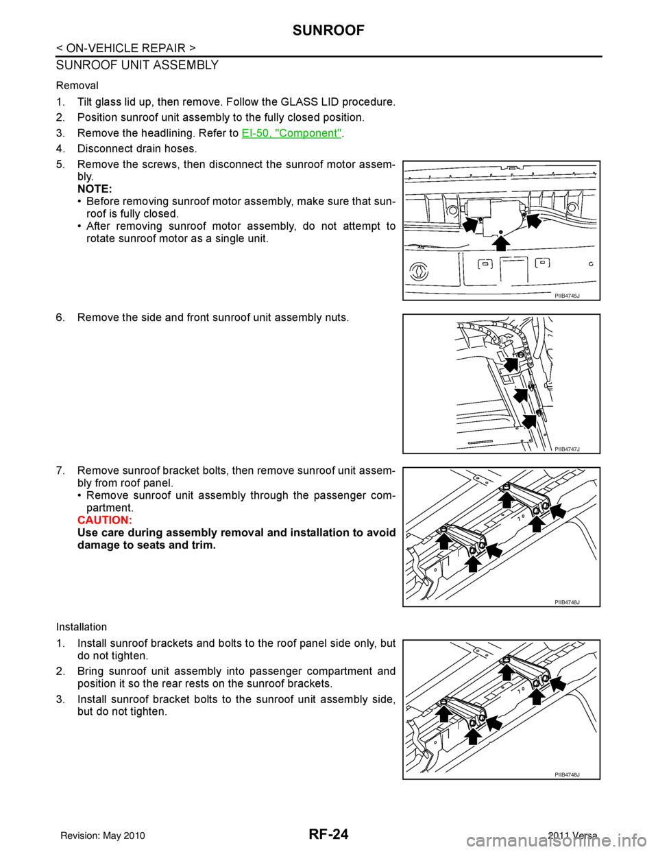
SUNROOF UNIT ASSEMBLY
Removal
1. Tilt glass lid up, then remove. Follow the GLASS LID procedure.
2. Position sunroof unit assembly to the fully closed position.
3. Remove the headlining. Refer to EI-50, "
Component".
4. Disconnect drain hoses.
5. Remove the screws, then disconnect the sunroof motor assem- bly.
NOTE:
• Before removing sunroof motor assembly, make sure that sun-roof is fully closed.
• After removing sunroof motor assembly, do not attempt to rotate sunroof motor as a single unit.
6. Remove the side and front sunroof unit assembly nuts.
7. Remove sunroof bracket bolts, then remove sunroof unit assem- bly from roof panel.
• Remove sunroof unit assembly through the passenger com-
partment.
CAUTION:
Use care during assembly removal and installation to avoid
damage to seats and trim.
Installation
1. Install sunroof brackets and bolts to the roof panel side only, but do not tighten.
2. Bring sunroof unit assembly into passenger compartment and position it so the rear rests on the sunroof brackets.
3. Install sunroof bracket bolts to the sunroof unit assembly side, but do not tighten.
PIIB4745J
PIIB4747J
PIIB4748J
PIIB4748J
Revision: May 2010 2011 Versa
Page 3551 of 3787
RF-28
< ON-VEHICLE REPAIR >
SUNROOF
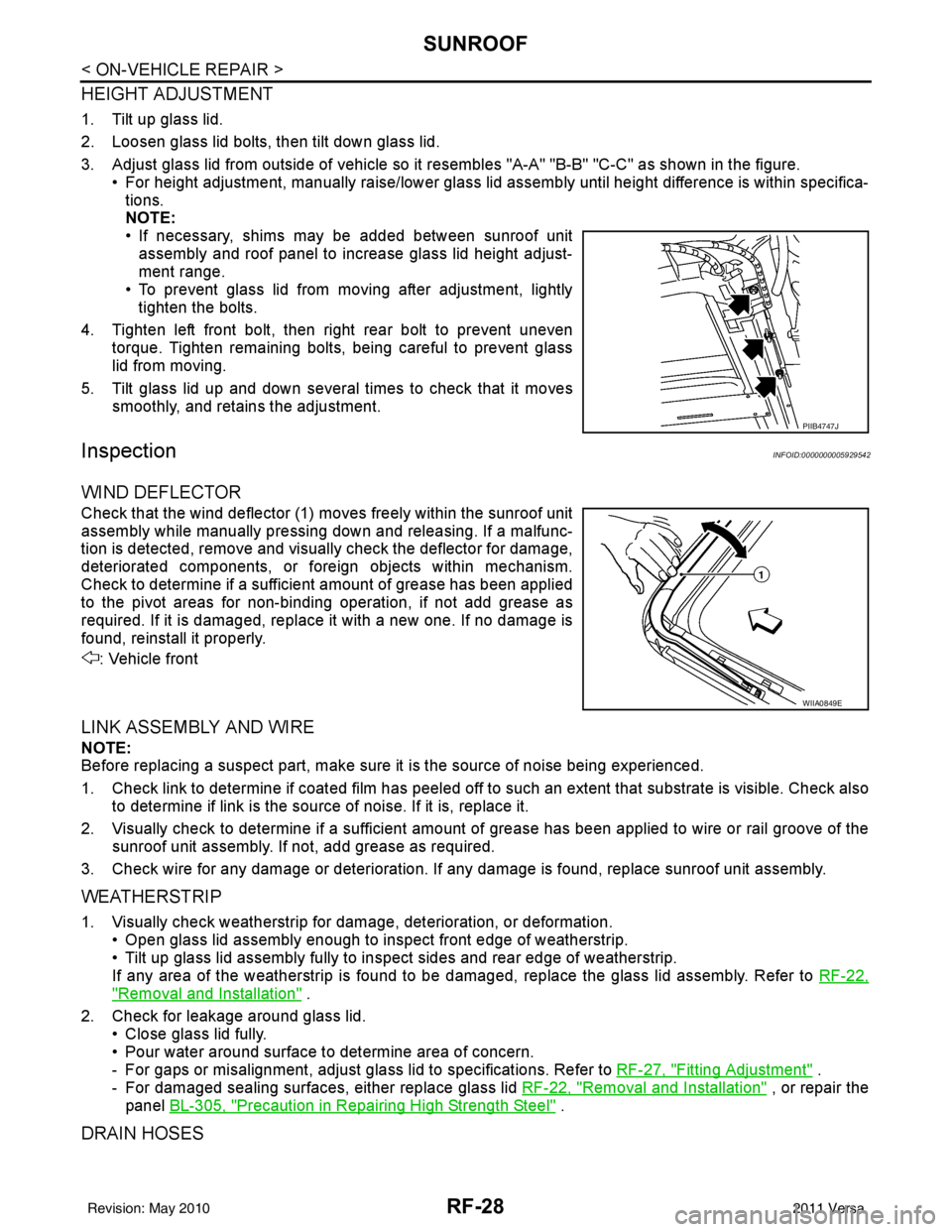
HEIGHT ADJUSTMENT
1. Tilt up glass lid.
2. Loosen glass lid bolts, then tilt down glass lid.
3. Adjust glass lid from outside of vehicle so it resembles "A-A" "B-B" "C-C" as shown in the figure.
• For height adjustment, manually raise/lower glass lid assembly until height difference is within specifica-
tions.
NOTE:
• If necessary, shims may be added between sunroof unit
assembly and roof panel to increase glass lid height adjust-
ment range.
• To prevent glass lid from moving after adjustment, lightly tighten the bolts.
4. Tighten left front bolt, then right rear bolt to prevent uneven torque. Tighten remaining bolts, being careful to prevent glass
lid from moving.
5. Tilt glass lid up and down several times to check that it moves smoothly, and retains the adjustment.
InspectionINFOID:0000000005929542
WIND DEFLECTOR
Check that the wind deflector (1) moves freely within the sunroof unit
assembly while manually pressing down and releasing. If a malfunc-
tion is detected, remove and visually check the deflector for damage,
deteriorated components, or foreign objects within mechanism.
Check to determine if a sufficient amount of grease has been applied
to the pivot areas for non-binding operation, if not add grease as
required. If it is damaged, replace it with a new one. If no damage is
found, reinstall it properly.
: Vehicle front
LINK ASSEMBLY AND WIRE
NOTE:
Before replacing a suspect part, make sure it is the source of noise being experienced.
1. Check link to determine if coated film has peeled off to such an extent that substrate is visible. Check also
to determine if link is the source of noise. If it is, replace it.
2. Visually check to determine if a sufficient amount of grease has been applied to wire or rail groove of the sunroof unit assembly. If not, add grease as required.
3. Check wire for any damage or deterioration. If any damage is found, replace sunroof unit assembly.
WEATHERSTRIP
1. Visually check weatherstrip for damage, deterioration, or deformation.
• Open glass lid assembly enough to inspect front edge of weatherstrip.
• Tilt up glass lid assembly fully to in spect sides and rear edge of weatherstrip.
If any area of the weatherstrip is found to be damaged, replace the glass lid assembly. Refer to RF-22,
"Removal and Installation" .
2. Check for leakage around glass lid. • Close glass lid fully.
• Pour water around surface to determine area of concern.
- For gaps or misalignment, adjust glass lid to specifications. Refer to RF-27, "
Fitting Adjustment" .
- For damaged sealing surfaces, either replace glass lid RF-22, "
Removal and Installation" , or repair the
panel BL-305, "
Precaution in Repairing High Strength Steel" .
DRAIN HOSES
PIIB4747J
WIIA0849E
Revision: May 2010 2011 Versa
Page 3553 of 3787

RF-30
< ON-VEHICLE REPAIR >
SUNROOF
1. Remove headlining. Refer to EI-50, "Component".
2. Visually check drain hoses for: • Proper connection at sunroof unit assembly.
• Damage, pinch, cracks, deterioration.
• Proper fastening and routing on body panels.
3. Pour water through drain hoses to determine watertight performance.
If a damaged or leaking portion in any drain hose is found, replace entire drain hose as an assembly.
1. Drain hose2. Fender 3. Seal
4. Fascia 5. Drain hose rear LH6. Drain hose rear RH
7. Drain hose front LH 8. Drain hose front RH 9. Sunroof unit assembly
Vehicle front
Revision: May 2010 2011 Versa
Page 3578 of 3787

SB-12
< ON-VEHICLE REPAIR >
TOP TETHER STRAP CHILD RESTRAINT
TOP TETHER STRAP CHILD RESTRAINT
Removal and InstallationINFOID:0000000005929625
REMOVAL
1. Disconnect the negative battery cable.
2. Remove the rear parcel shelf finisher. Refer to EI-47, "
Removal and Installation".
3. Remove the bolt (A), then remove the top tether bracket (1) from the body panel.
: Vehicle front
INSTALLATION
Installation is in the reverse order of removal.
LHIA0134E
Revision: May 2010 2011 Versa
Page 3608 of 3787
PRECAUTIONSSE-3
< SERVICE INFORMATION >
C
DE
F
G H
J
K L
M A
B
SE
N
O P
5. When the repair work is completed, return the ignition switch to the ″LOCK ″ position before connecting
the battery cables. (At this time, the steering lock mechanism will engage.)
6. Perform a self-diagnosis check of al l control units using CONSULT-III.
Service NoticeINFOID:0000000005929597
• When removing or installing various parts, place a cloth or padding onto the vehicle body to prevent
scratches.
• Handle trim, molding instruments, grille, etc. carefully during removing or installing. Be careful not to oil or
damage them.
• Apply sealing compound where necessary when installing parts.
• When applying sealing compound, be careful that the sealing compound does not protrude from parts.
• When replacing any metal parts (for example body outer panel, member, etc.), be sure to take rust preven-
tion measures.
PrecautionINFOID:0000000005929598
• When removing or disassembling any part, be careful not to damage or deform it. Protect parts which may
get in the way with cloth.
• When removing parts with a screwdriver or other tool , protect parts by wrapping tools with vinyl or tape.
• Keep removed parts protected with cloth.
• If a clip is deformed or damaged, replace it.
• If an unreusable part is removed, replace it with a new one.
• Tighten bolts and nuts firmly to the specified torque.
• After re-assembly has been completed, make sure each part functions correctly.
• Remove stains in the following way.
Water-soluble stains:
Dip a soft cloth in warm water, and then squeeze it tight ly. After wiping the stain, wipe with a soft dry cloth.
Oil stain:
Dissolve a synthetic detergent in warm water (density of 2 to 3% or less), dip the cloth, then clean off the stain
with the cloth. Next, dip the cloth in fresh water and squeeze it tightly. Then clean off the detergent completely.
Then wipe the area with a soft dry cloth.
• Do not use any organic solvent, such as thinner or benzine.
Revision: May 2010 2011 Versa
Page 3611 of 3787
SE-6
< SERVICE INFORMATION >
SQUEAK AND RATTLE TROUBLE DIAGNOSES
If the noise can be duplicated easily during the test drive, to help identify the source of the noise, try to dupli-
cate the noise with the vehicle stopped by doing one or all of the following:
1) Close a door.
2) Tap or push/pull around the area where the noise appears to be coming from.
3) Rev the engine.
4) Use a floor jack to recreate vehicle “twist”.
5) At idle, apply engine load (electrical load, half-clutch on M/T model, shift selector in the drive position for
CVT and A/T models).
6) Raise the vehicle on a hoist and hit a tire with a rubber hammer.
• Drive the vehicle and attempt to duplicate the conditions the customer states exist when the noise occurs.
• If it is difficult to duplicate the noise, drive the v ehicle slowly on an undulating or rough road to stress the
vehicle body.
CHECK RELATED SERVICE BULLETINS
After verifying the customer concern or symptom, chec k ASIST for Technical Service Bulletins (TSBs) related
to that concern or symptom.
If a TSB relates to the symptom, follo w the procedure to repair the noise.
LOCATE THE NOISE AND IDENTIFY THE ROOT CAUSE
1. Narrow down the noise to a general area.To help pinpoint the source of the noise, use a listening tool
(Chassis Ear: J-39570, Engine Ear: J-39565 and mechanic's stethoscope).
2. Narrow down the noise to a more specific area and identify the cause of the noise by:
• removing the components in the area that you suspect the noise is coming from.
Do not use too much force when removing clips and fasteners, otherwise clips and fasteners can be broken
or lost during the repair, resulting in the creation of new noise.
• tapping or pushing/pulling the component that you suspect is causing the noise.
Do not tap or push/pull the component with excessive force, otherwise the noise will be eliminated only tem-
porarily.
• feeling for a vibration with your hand by touching the component(s) that you suspect is (are) causing the
noise.
• placing a piece of paper between components that you suspect are causing the noise.
• looking for loose components and contact marks. Refer to SE-7, "
Generic Squeak and Rattle Troubleshooting" .
REPAIR THE CAUSE
• If the cause is a loose component, tighten the component securely.
• If the cause is insufficient clearance between components:
- separate components by repositioning or loos ening and retightening the component, if possible.
- insulate components with a suitable insulator such as urethane pads, foam blocks, felt cloth tape or urethane tape. A NISSAN Squeak and Rattle Kit (J-43980) is av ailable through your authorized NISSAN Parts Depart-
ment.
CAUTION:
Do not use excessive force as many components are constructed of plastic and may be damaged.
Always check with the Parts Department for the latest parts information.
The following materials are contained in the NISSAN Squeak and Rattle Kit (J-43980). Each item can be
ordered separately as needed.
URETHANE PADS [1.5 mm (0.059 in) thick]
Insulates connectors, harness, etc.
76268-9E005: 100 ×135 mm (3.94× 5.31 in)/76884-71L01: 60 ×85 mm (2.36 ×3.35 in)/76884-71L02: 15 ×25
mm (0.59× 0.98 in)
INSULATOR (Foam blocks)
Insulates components from contact. Can be used to fill space behind a panel.
73982-9E000: 45 mm (1.77 in) thick, 50 ×50 mm (1.97 ×1.97 in)/73982-50Y00: 10 mm (0.39 in) thick,
50× 50 mm (1.97 ×1.97 in)
INSULATOR (Light foam block)
80845-71L00: 30 mm (1.18 in) thick, 30 ×50 mm (1.18 ×1.97 in)
FELT CLOTH TAPE
Used to insulate where movemen t does not occur. Ideal for instrument panel applications.
68370-4B000: 15 ×25 mm (0.59× 0.98 in) pad/68239-13E00: 5 mm (0.20 in ) wide tape roll. The following
materials not found in the kit can also be used to repair squeaks and rattles.
UHMW (TEFLON) TAPE
Revision: May 2010 2011 Versa