Brake system NISSAN TIIDA 2011 Service Owner's Guide
[x] Cancel search | Manufacturer: NISSAN, Model Year: 2011, Model line: TIIDA, Model: NISSAN TIIDA 2011Pages: 3787, PDF Size: 78.35 MB
Page 619 of 3787
INTELLIGENT KEY SYSTEMBL-109
< SERVICE INFORMATION >
C
DE
F
G H
J
K L
M A
B
BL
N
O P
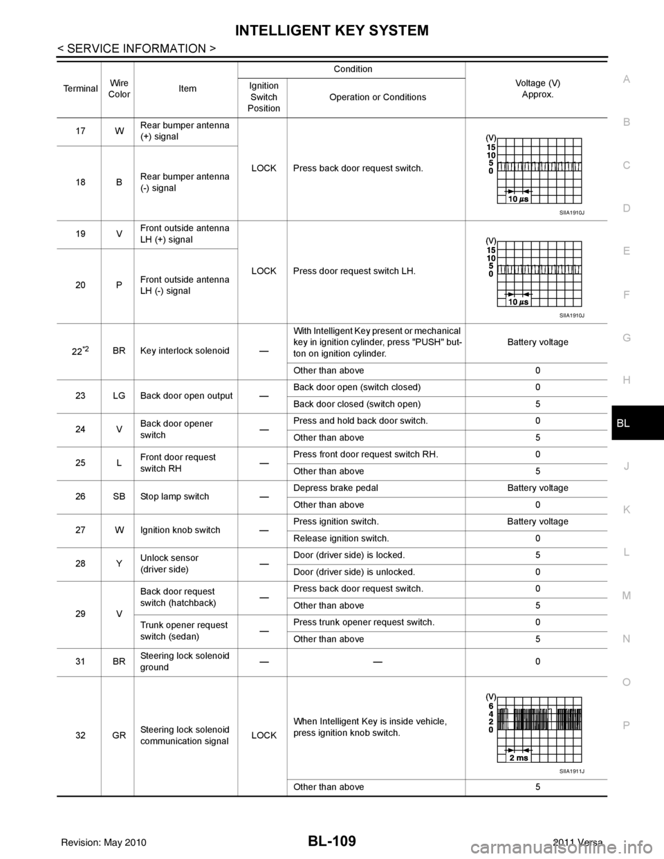
17 W Rear bumper antenna
(+) signal
LOCK Press back door request switch.
18 B Rear bumper antenna
(-) signal
19 V Front outside antenna
LH (+) signal
LOCK Press door request switch LH.
20 P Front outside antenna
LH (-) signal
22
*2BR Key interlock solenoid — With Intelligent Key present or mechanical
key in ignition cylinder, press "PUSH" but-
ton on ignition cylinder.
Battery voltage
Other than above 0
23 LG Back door open output — Back door open (switch closed)
0
Back door closed (switch open) 5
24 V Back door opener
switch —Press and hold back door switch.
0
Other than above 5
25 L Front door request
switch RH —Press front door request switch RH.
0
Other than above 5
26 SB Stop lamp switch —Depress brake pedal
Battery voltage
Other than above 0
27 W Ignition knob switch — Press ignition switch.
Battery voltage
Release ignition switch. 0
28 Y Unlock sensor
(driver side) —Door (driver si
de) is locked. 5
Door (driver side ) is unlocked. 0
29 V Back door request
switch (hatchback)
—Press back door request switch.
0
Other than above 5
Trunk opener request
switch (sedan) —Press trunk opener request switch.
0
Other than above 5
31 BR Steering lock solenoid
ground
——
0
32 GR Steering lock solenoid
communication signal LOCKWhen Intelligent Key is inside vehicle,
press ignition knob switch.
Other than above
5
Terminal
Wire
Color Item Condition
Voltage (V)Approx.
Ignition
Switch
Position Operation or Conditions
SIIA1910J
SIIA1910J
SIIA1911J
Revision: May 2010
2011 Versa
Page 661 of 3787
INTELLIGENT KEY SYSTEMBL-151
< SERVICE INFORMATION >
C
DE
F
G H
J
K L
M A
B
BL
N
O P
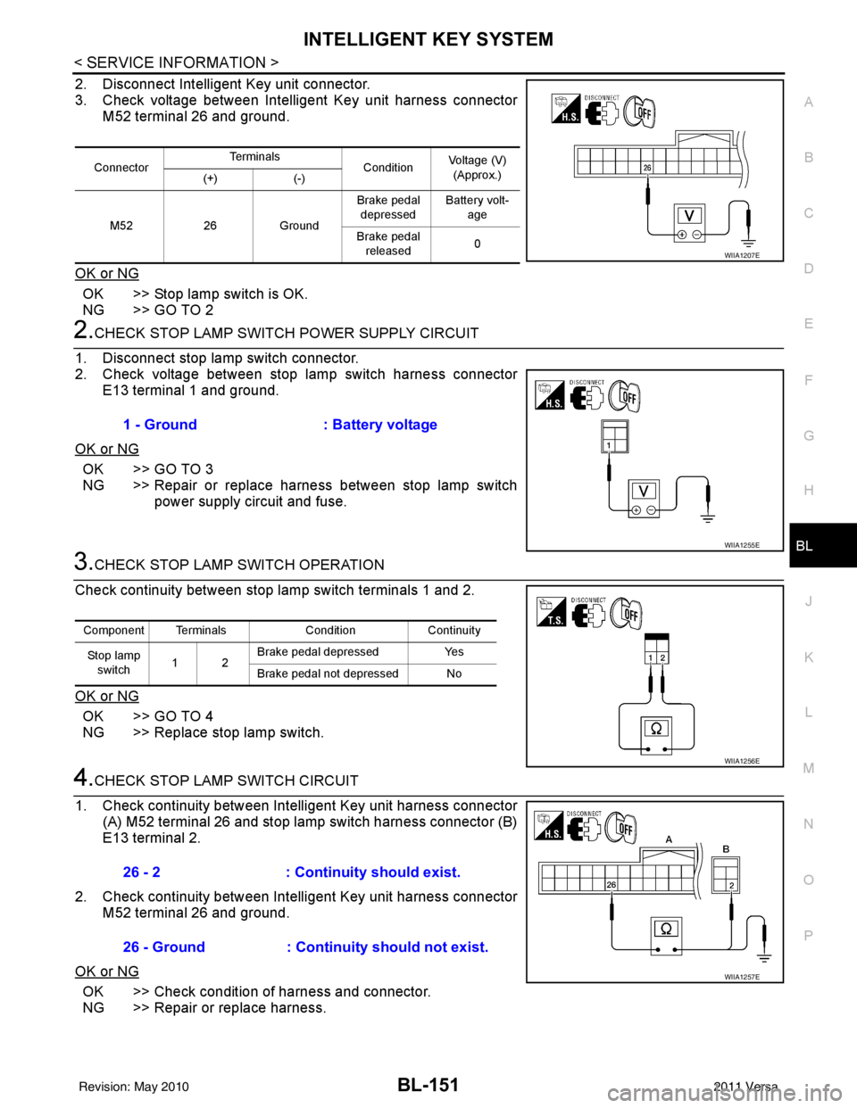
2. Disconnect Intelligent Key unit connector.
3. Check voltage between Intelligent Key unit harness connector M52 terminal 26 and ground.
OK or NG
OK >> Stop lamp switch is OK.
NG >> GO TO 2
2.CHECK STOP LAMP SWIT CH POWER SUPPLY CIRCUIT
1. Disconnect stop lamp switch connector.
2. Check voltage between stop lamp switch harness connector E13 terminal 1 and ground.
OK or NG
OK >> GO TO 3
NG >> Repair or replace harness between stop lamp switch power supply circuit and fuse.
3.CHECK STOP LAMP SWITCH OPERATION
Check continuity between stop lamp switch terminals 1 and 2.
OK or NG
OK >> GO TO 4
NG >> Replace stop lamp switch.
4.CHECK STOP LAMP SWITCH CIRCUIT
1. Check continuity between Intelligent Key unit harness connector (A) M52 terminal 26 and stop lamp switch harness connector (B)
E13 terminal 2.
2. Check continuity between Intelligent Key unit harness connector M52 terminal 26 and ground.
OK or NG
OK >> Check condition of harness and connector.
NG >> Repair or replace harness.
Connector Te r m i n a l s
ConditionVoltage (V)
(Approx.)
(+) (-)
M52 26Ground Brake pedal
depressed Battery volt-
age
Brake pedal released 0
WIIA1207E
1 - Ground
: Battery voltage
WIIA1255E
Component Terminals ConditionContinuity
Stop lamp switch 12 Brake pedal depressed
Yes
Brake pedal not depressed No
WIIA1256E
26 - 2 : Continuity should exist.
26 - Ground : Continuity should not exist.
WIIA1257E
Revision: May 2010 2011 Versa
Page 662 of 3787
BL-152
< SERVICE INFORMATION >
INTELLIGENT KEY SYSTEM
Stop Lamp Switch Check (With M/T)
INFOID:0000000005929360
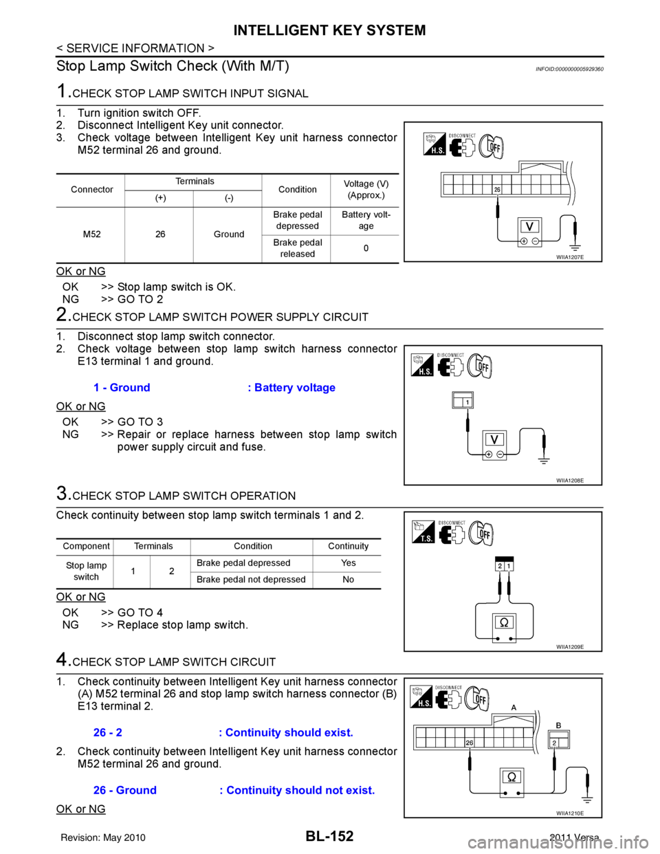
1.CHECK STOP LAMP SWITCH INPUT SIGNAL
1. Turn ignition switch OFF.
2. Disconnect Intelligent Key unit connector.
3. Check voltage between Intelligent Key unit harness connector M52 terminal 26 and ground.
OK or NG
OK >> Stop lamp switch is OK.
NG >> GO TO 2
2.CHECK STOP LAMP SWIT CH POWER SUPPLY CIRCUIT
1. Disconnect stop lamp switch connector.
2. Check voltage between stop lamp switch harness connector E13 terminal 1 and ground.
OK or NG
OK >> GO TO 3
NG >> Repair or replace harness between stop lamp switch power supply circuit and fuse.
3.CHECK STOP LAMP SWITCH OPERATION
Check continuity between stop lamp switch terminals 1 and 2.
OK or NG
OK >> GO TO 4
NG >> Replace stop lamp switch.
4.CHECK STOP LAMP SWITCH CIRCUIT
1. Check continuity between Inte lligent Key unit harness connector
(A) M52 terminal 26 and stop lamp switch harness connector (B)
E13 terminal 2.
2. Check continuity between Inte lligent Key unit harness connector
M52 terminal 26 and ground.
OK or NG
Connector Te r m i n a l s
ConditionVoltage (V)
(Approx.)
(+) (-)
M52 26Ground Brake pedal
depressed Battery volt-
age
Brake pedal released 0
WIIA1207E
1 - Ground
: Battery voltage
WIIA1208E
Component Terminals ConditionContinuity
St op la mp switch 12 Brake pedal depressed
Yes
Brake pedal not depressed No
WIIA1209E
26 - 2 : Continuity should exist.
26 - Ground : Continuity should not exist.
WIIA1210E
Revision: May 2010 2011 Versa
Page 741 of 3787
VEHICLE SECURITY (THEFT WARNING) SYSTEMBL-231
< SERVICE INFORMATION >
C
DE
F
G H
J
K L
M A
B
BL
N
O P
10*1W CVT or A/T shift selec-
tor (park position
switch)
ONShift lever in park position.
0
Other than above Battery voltage
11 SB Power source (Fus e) — —Battery voltage
12 B Ground —— 0
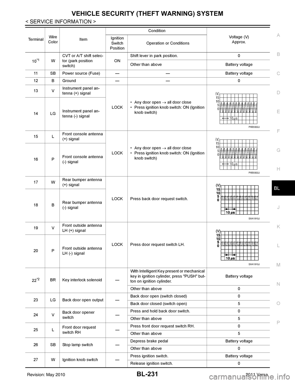
13 V Instrument panel an-
tenna (+) signal
LOCK• Any door open
→ all door close
• Press ignition knob switch: ON (Ignition knob switch)
14 LG Instrument panel an-
tenna (-) signal
15 L Front console antenna
(+) signal
LOCK• Any door open
→ all door close
• Press ignition knob switch: ON (Ignition knob switch)
16 P Front console antenna
(-) signal
17 W Rear bumper antenna
(+) signal
LOCK Press back door request switch.
18 B Rear bumper antenna
(-) signal
19 V Front outside antenna
LH (+) signal
LOCK Press door request switch LH.
20 P Front outside antenna
LH (-) signal
22
*2BR Key interlock solenoid — With Intelligent Key present or mechanical
key in ignition cylinder, press "PUSH" but-
ton on ignition cylinder.
Battery voltage
Other than above 0
23 LG Back door open output — Back door open (switch closed)
0
Back door closed (switch open) 5
24 V Back door opener
switch —Press and hold back door switch.
0
Other than above 5
25 L Front door request
switch RH
—Press front door request switch RH.
0
Other than above 5
26 SB Stop lamp switch —Depress brake pedal
Battery voltage
Other than above 0
27 W Ignition knob switch — Press ignition switch.
Battery voltage
Release ignition switch. 0
Terminal
Wire
Color Item Condition
Voltage (V)Approx.
Ignition
Switch
Position Operation or Conditions
PIIB5502J
PIIB5502J
SIIA1910J
SIIA1910J
Revision: May 2010
2011 Versa
Page 848 of 3787

BR-1
BRAKES
C
DE
G H
I
J
K L
M
SECTION BR
A
B
BR
N
O P
CONTENTS
BRAKE SYSTEM
SERVICE INFORMATION .. ..........................2
PRECAUTIONS .............................................. .....2
Precaution for Supplemental Restraint System
(SRS) "AIR BAG" and "SEAT BELT PRE-TEN-
SIONER" ............................................................. ......
2
Precaution Necessary for Steering Wheel Rota-
tion After Battery Disconnect ............................... ......
2
Precaution for Brake System ....................................3
PREPARATION ...................................................4
Special Service Tool ........................................... ......4
Commercial Service Tool ..........................................4
NOISE, VIBRATION AND HARSHNESS
(NVH) TROUBLESHOOTING .............................
5
NVH Troubleshooting Chart ................................ ......5
BRAKE PEDAL .............................................. .....6
Inspection and Adjustment .................................. ......6
Removal and Installation ...........................................7
BRAKE FLUID ................................................ .....9
On Board Inspection ........................................... ......9
Drain and Refill ..........................................................9
Bleeding Brake System .............................................9
BRAKE TUBE AND HOSE ................................11
Hydraulic Circuit .................................................. ....11
Front Brake Tube and Hose ....................................12
Rear Brake Tube and Hose ....................................12
Inspection After Installation .....................................13
DUAL PROPORTIONING VALVE .....................14
Removal and Installation .........................................14
Inspection ............................................................ ....14
BRAKE MASTER CYLINDER ........................ ....15
On-Board Inspection ........................................... ....15
Removal and Installation ..................................... ....15
Disassembly and Assembly .....................................16
BRAKE BOOSTER ...........................................20
On Board Inspection ............................................ ....20
Removal and Installation .........................................21
VACUUM LINES ...............................................23
Component ..............................................................23
Removal and Installation .........................................23
Inspection ................................................................23
FRONT DISC BRAKE .......................................25
On Board Inspection ............................................ ....25
Component ..............................................................25
Removal and Installation of Brake Pad ...................26
Removal and Installation of Brake Caliper Assem-
bly ........................................................................ ....
30
Disassembly and Assembly of Brake Caliper As-
sembly .....................................................................
31
Brake Burnishing Procedure ....................................34
REAR DRUM BRAKE .......................................35
Component .......................................................... ....35
Removal and Installation of Drum Brake Assembly
....
36
Removal and Installation of Wheel Cylinder ............39
Disassembly and Assembly of Wheel Cylinder .......39
SERVICE DATA AND SPECIFICATIONS
(SDS) .................................................................
40
General Specification ..............................................40
Brake Pedal .............................................................41
Check Valve ............................................................41
Brake Booster ..........................................................42
Front Disc Brake ......................................................42
Rear Drum Brake .....................................................42
Revision: May 2010 2011 Versa
Page 850 of 3787
PRECAUTIONSBR-3
< SERVICE INFORMATION >
C
DE
G H
I
J
K L
M A
B
BR
N
O P
5. When the repair work is completed, return the ignition switch to the ″LOCK ″ position before connecting
the battery cables. (At this time, the steering lock mechanism will engage.)
6. Perform a self-diagnosis check of al l control units using CONSULT-III.
Precaution for Brake SystemINFOID:0000000005928387
• Refill using recommended brake fluid. Refer to MA-14.
• Never reuse drained brake fluid.
• Be careful not to splash brake fluid on painted surface of body. If brake fluid is splashed on painted surfaces of body immediately wipe it off with cloth and then wash it away with water.
• To clean or wash all parts of master cylinder, disc brake caliper and wheel cylinder, use new brake fluid.
• Never use mineral oils such as gasoline or kerosene. They will ruin rubber parts of the hydraulic system.
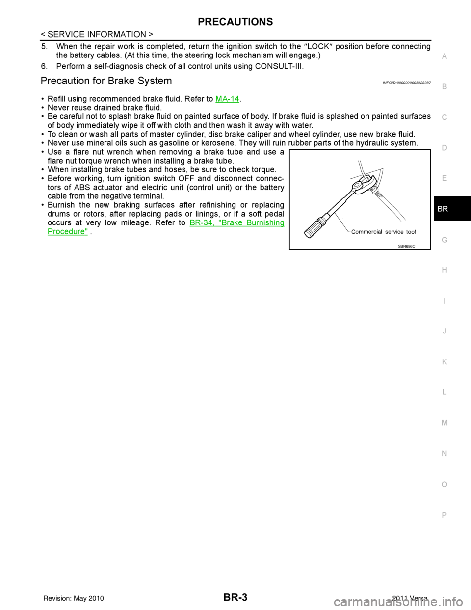
• Use a flare nut wrench when removing a brake tube and use a flare nut torque wrench when installing a brake tube.
• When installing brake tubes and hoses, be sure to check torque.
• Before working, turn igniti on switch OFF and disconnect connec-
tors of ABS actuator and electric unit (control unit) or the battery
cable from the negative terminal.
• Burnish the new braking surfaces after refinishing or replacing drums or rotors, after replacing p ads or linings, or if a soft pedal
occurs at very low mileage. Refer to BR-34, "
Brake Burnishing
Procedure" .
SBR686C
Revision: May 2010 2011 Versa
Page 856 of 3787
BRAKE FLUIDBR-9
< SERVICE INFORMATION >
C
DE
G H
I
J
K L
M A
B
BR
N
O P
BRAKE FLUID
On Board InspectionINFOID:0000000005928393
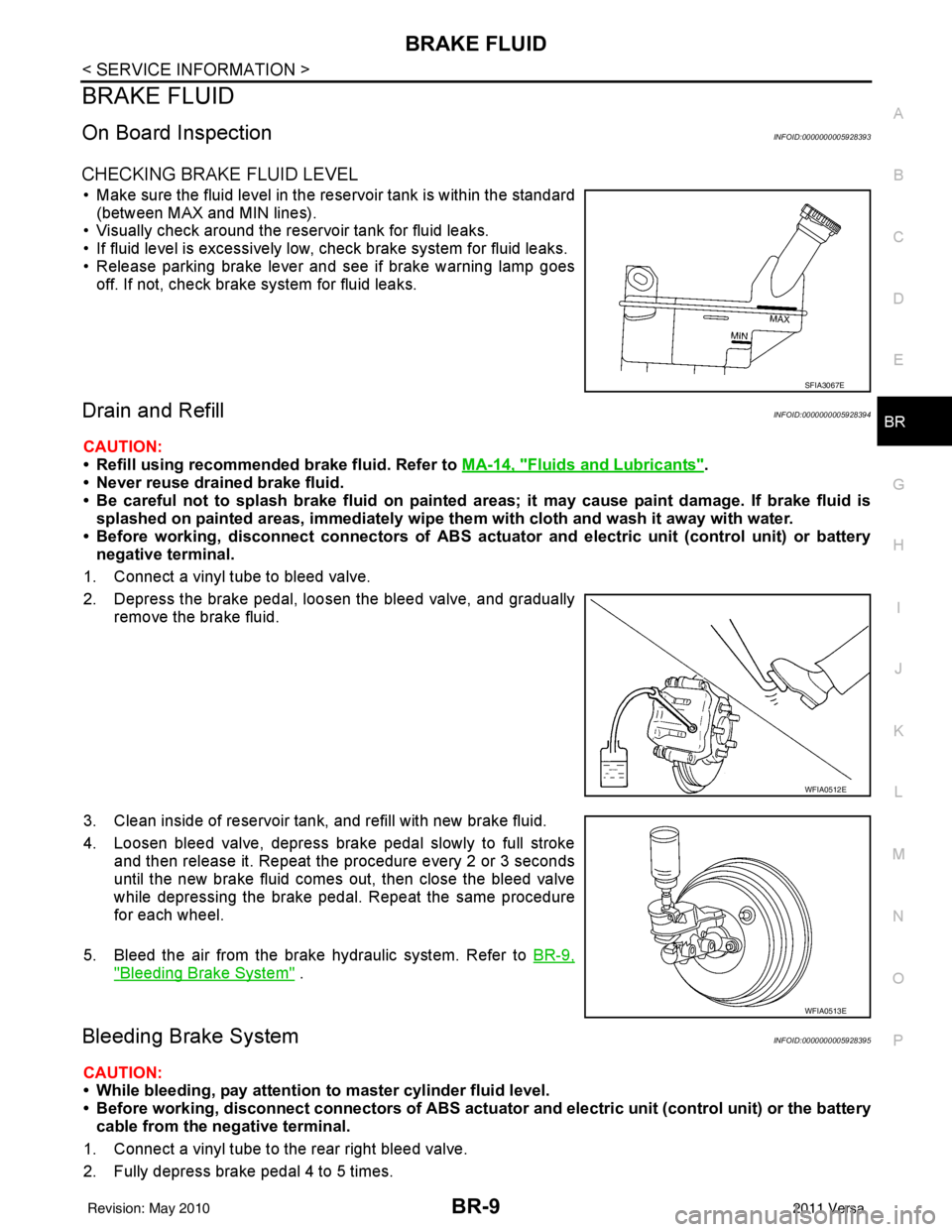
CHECKING BRAKE FLUID LEVEL
• Make sure the fluid level in the reservoir tank is within the standard (between MAX and MIN lines).
• Visually check around the reservoir tank for fluid leaks.
• If fluid level is excessively low, check brake system for fluid leaks.
• Release parking brake lever and see if brake warning lamp goes off. If not, check brake system for fluid leaks.
Drain and RefillINFOID:0000000005928394
CAUTION:
• Refill using recommended brake fluid. Refer to MA-14, "
Fluids and Lubricants".
• Never reuse drained brake fluid.
• Be careful not to splash brake fluid on painted areas; it may cause paint damage. If brake fluid is
splashed on painted areas, immediately wipe th em with cloth and wash it away with water.
• Before working, disconnect connect ors of ABS actuator and electric unit (control unit) or battery
negative terminal.
1. Connect a vinyl tube to bleed valve.
2. Depress the brake pedal, loosen the bleed valve, and gradually remove the brake fluid.
3. Clean inside of reservoir tank, and refill with new brake fluid.
4. Loosen bleed valve, depress brake pedal slowly to full stroke and then release it. Repeat the procedure every 2 or 3 seconds
until the new brake fluid comes out, then close the bleed valve
while depressing the brake pedal . Repeat the same procedure
for each wheel.
5. Bleed the air from the brake hydraulic system. Refer to BR-9,
"Bleeding Brake System" .
Bleeding Brake SystemINFOID:0000000005928395
CAUTION:
• While bleeding, pay attention to master cylinder fluid level.
• Before working, disconnect connectors of ABS actuator and electri c unit (control unit) or the battery
cable from the negative terminal.
1. Connect a vinyl tube to the rear right bleed valve.
2. Fully depress brake pedal 4 to 5 times.
SFIA3067E
WFIA0512E
WFIA0513E
Revision: May 2010 2011 Versa
Page 859 of 3787
BR-12
< SERVICE INFORMATION >
BRAKE TUBE AND HOSE
• All tubes and hoses must be free from excessive bending, twisting and pulling.
• Make sure there is no interference with other part s when turning steering both clockwise and coun-
terclockwise.
• Brake tubes and hoses are an important safety part. Always disassemble the parts and retighten
their fittings, if a brake fluid leak is detected. Replace applicable part with a new one, if damaged part
is detected.
• Be careful not to splash brake fluid on painted areas; it may cause paint damage. If brake fluid is
splashed on painted surfaces of body , immediately wipe them with cloth and then wash it away with
water.
• Do not bend or twist brake hose sharply, or strongly pull it.
• When removing components, cover brake line connect ions so that dirt, dust, or other foreign mat-
ters do not get in.
• Refill using recommended brake fluid. Refer to MA-14, "
Fluids and Lubricants".
• Never reuse drained brake fluid.
Front Brake Tube and HoseINFOID:0000000005928397
REMOVAL
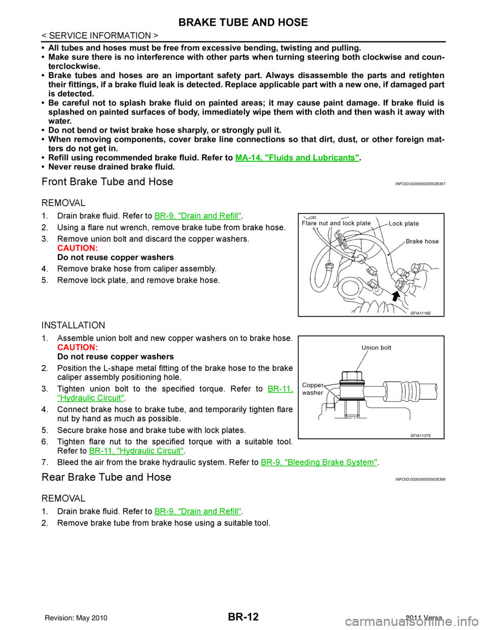
1. Drain brake fluid. Refer to BR-9, "Drain and Refill".
2. Using a flare nut wrench, remove brake tube from brake hose.
3. Remove union bolt and discard the copper washers. CAUTION:
Do not reuse copper washers
4. Remove brake hose from caliper assembly.
5. Remove lock plate, and remove brake hose.
INSTALLATION
1. Assemble union bolt and new copper washers on to brake hose. CAUTION:
Do not reuse copper washers
2. Position the L-shape metal fitting of the brake hose to the brake caliper assembly positioning hole.
3. Tighten union bolt to the specified torque. Refer to BR-11,
"Hydraulic Circuit".
4. Connect brake hose to brake tube, and temporarily tighten flare nut by hand as much as possible.
5. Secure brake hose and brake tube with lock plates.
6. Tighten flare nut to the specified torque with a suitable tool. Refer to BR-11, "
Hydraulic Circuit".
7. Bleed the air from the brake hydraulic system. Refer to BR-9, "
Bleeding Brake System".
Rear Brake Tube and HoseINFOID:0000000005928398
REMOVAL
1. Drain brake fluid. Refer to BR-9, "Drain and Refill".
2. Remove brake tube from brake hose using a suitable tool.
SFIA1118E
SFIA1137E
Revision: May 2010 2011 Versa
Page 860 of 3787
BRAKE TUBE AND HOSEBR-13
< SERVICE INFORMATION >
C
DE
G H
I
J
K L
M A
B
BR
N
O P
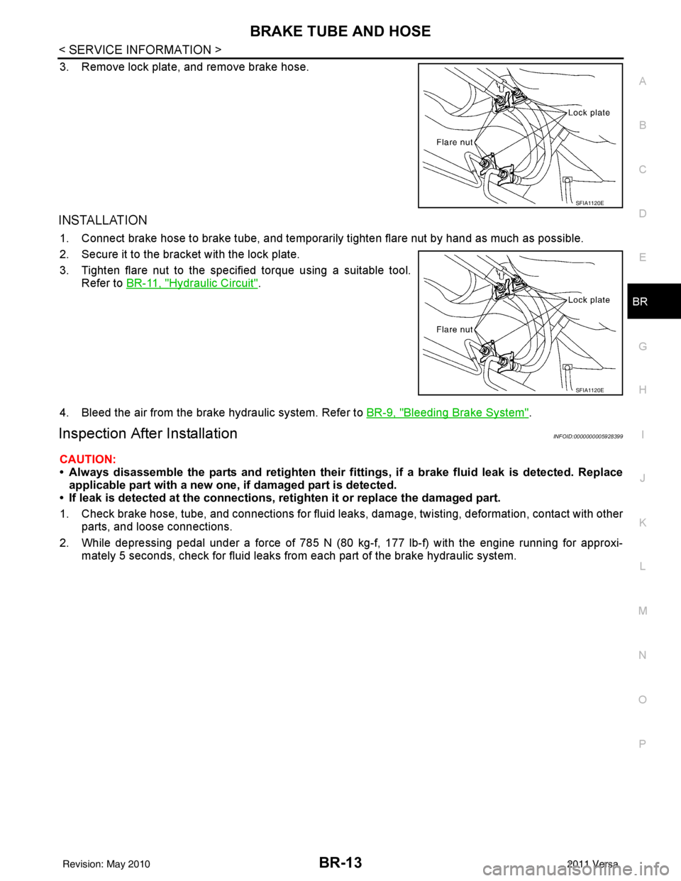
3. Remove lock plate, and remove brake hose.
INSTALLATION
1. Connect brake hose to brake tube, and temporaril y tighten flare nut by hand as much as possible.
2. Secure it to the bracket with the lock plate.
3. Tighten flare nut to the specified torque using a suitable tool. Refer to BR-11, "
Hydraulic Circuit".
4. Bleed the air from the brake hydraulic system. Refer to BR-9, "
Bleeding Brake System".
Inspection After InstallationINFOID:0000000005928399
CAUTION:
• Always disassemble the parts and retighten their fitti ngs, if a brake fluid leak is detected. Replace
applicable part with a new one, if damaged part is detected.
• If leak is detected at the connections, retighten it or replace the damaged part.
1. Check brake hose, tube, and connections for fluid leak s, damage, twisting, deformation, contact with other
parts, and loose connections.
2. While depressing pedal under a force of 785 N (80 kg-f, 177 lb-f) with the engine running for approxi- mately 5 seconds, check for fluid leaks from each part of the brake hydraulic system.
SFIA1120E
SFIA1120E
Revision: May 2010 2011 Versa
Page 861 of 3787
BR-14
< SERVICE INFORMATION >
DUAL PROPORTIONING VALVE
DUAL PROPORTIONING VALVE
Removal and InstallationINFOID:0000000005928400
Removal
1. Remove the cowl top. Refer to EI-24, "Removal and Installation".
2. Disconnect brake lines from dual proportioning valve. • Mark brake lines for installation.
3. Remove dual proportioning valve bolt and dual proportioning valve.
4. Remove two bolts and bracket.
Installation
Installation is in the reverse order of removal.
• When installing brake lines to the dual proportioning valve, tighten to specifications. Refer to BR-11,
"Hydraulic Circuit".
InspectionINFOID:0000000005928401
CAUTION:
• Carefully monitor brake fluid level at master cylinder.
• Use the recommended new brake fluid. Refer to MA-14, "
Fluids and Lubricants".
• Be careful not to splash brake fluid on painted areas; it may cause paint damage. If brake fluid is
splashed on paint areas, wash it away with water immediately.
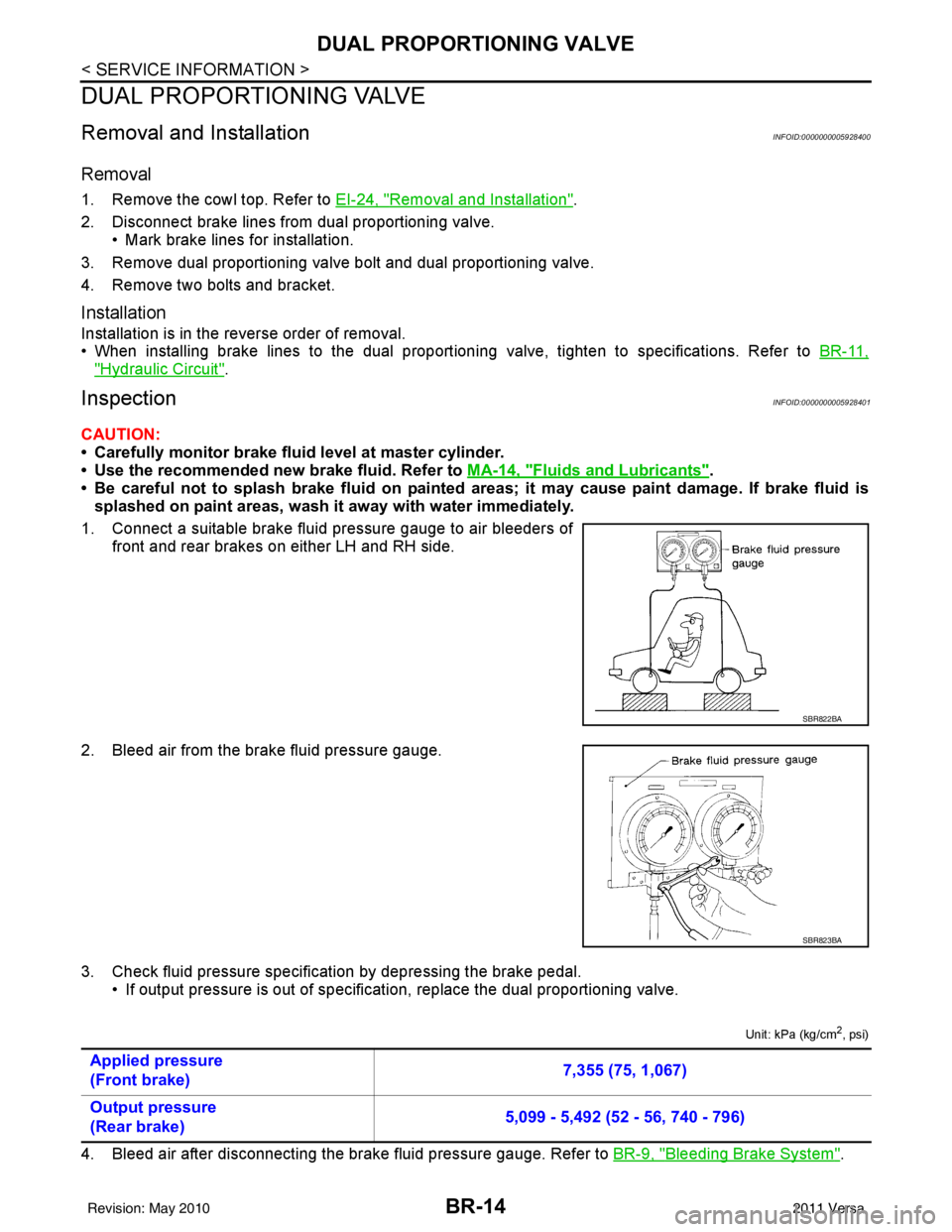
1. Connect a suitable brake fluid pressure gauge to air bleeders of front and rear brakes on either LH and RH side.
2. Bleed air from the brake fluid pressure gauge.
3. Check fluid pressure specific ation by depressing the brake pedal.
• If output pressure is out of specification, replace the dual proportioning valve.
Unit: kPa (kg/cm2, psi)
4. Bleed air after disconnecting the brake fluid pressure gauge. Refer to BR-9, "Bleeding Brake System".
SBR822BA
SBR823BA
Applied pressure
(Front brake) 7,355 (75, 1,067)
Output pressure
(Rear brake) 5,099 - 5,492 (52 - 56, 740 - 796)
Revision: May 2010
2011 Versa