Brake system NISSAN TIIDA 2011 Service Manual PDF
[x] Cancel search | Manufacturer: NISSAN, Model Year: 2011, Model line: TIIDA, Model: NISSAN TIIDA 2011Pages: 3787, PDF Size: 78.35 MB
Page 968 of 3787
![NISSAN TIIDA 2011 Service Manual PDF TROUBLE DIAGNOSIS FOR SELF-DIAGNOSTIC ITEMS
BRC-79
< SERVICE INFORMATION > [VDC/TCS/ABS]
C
D
E
G H
I
J
K L
M A
B
BRC
N
O P
Check the self-diagnosis results.
Is the above displayed in the self-diagnosi](/img/5/57396/w960_57396-967.png "NISSAN TIIDA 2011 Service Manual PDF TROUBLE DIAGNOSIS FOR SELF-DIAGNOSTIC ITEMS
BRC-79
< SERVICE INFORMATION > [VDC/TCS/ABS]
C
D
E
G H
I
J
K L
M A
B
BRC
N
O P
Check the self-diagnosis results.
Is the above displayed in the self-diagnosi")
TROUBLE DIAGNOSIS FOR SELF-DIAGNOSTIC ITEMS
BRC-79
< SERVICE INFORMATION > [VDC/TCS/ABS]
C
D
E
G H
I
J
K L
M A
B
BRC
N
O P
Check the self-diagnosis results.
Is the above displayed in the self-diagnosis display items?
YES >> GO TO 2.
NO >> Inspection End.
2.CONNECTOR INSPECTION
1. Disconnect the ABS actuator and el ectric unit (control unit) and brake fluid level switch connectors.
2. Check the terminals for deformation, disconnection, looseness or damage.
OK or NG
OK >> GO TO 3.
NG >> Repair or replace as necessary.
3.CHECK TRANSMISSION RANGE SWITCH
Perform transmission range switch inspection. Refer to AT-94, "
Component Inspection" (with A/T) or CVT-65,
"Component Inspection" (with CVT).
Is the inspection result normal?
YES >> Replace ABS actuator and electr ic unit (control unit). Refer to BRC-89, "Removal and Installa-
tion".
NO >> Repair or replace malfunctioning components.
CAN Communication System InspectionINFOID:0000000005928496
INSPECTION PROCEDURE
1.SELF-DIAGNOSIS RESULT CHECK
Check the self-diagnosis results.
Is the above displayed in the self-diagnosis display items?
YES >> GO TO 2.
NO >> Inspection End.
2.CHECK CONNECTOR
1. Disconnect the ABS actuator and electric unit (control unit) connector, and check the terminals for defor- mation, disconnection, looseness, and so on. If there is a malfunction, repair or replace the terminals.
2. Reconnect connector to perform self-diagnosis. Refer to BRC-60, "
CONSULT-III Function (ABS)".
Is
“CAN COMM CIRCUIT” displayed in the self-diagnosis display items?
YES >> Refer to LAN-17, "Trouble Diagnosis Flow Chart".
NO >> Connector terminal connection is loose, damaged, open, or shorted.
Component InspectionINFOID:0000000005928497
VDC OFF SWITCH
Self-diagnosis results
PNP POS SIG
Self-diagnosis results
ST ANG SEN COM CIR CAN COMM CIRCUIT
Revision: May 2010 2011 Versa
Page 971 of 3787
![NISSAN TIIDA 2011 Service Manual PDF BRC-82
< SERVICE INFORMATION >[VDC/TCS/ABS]
TROUBLE DIAGNOSES FOR SYMPTOMS
3.CHECK CONNECTOR AND BRAKING PERFORMANCE
1. Disconnect ABS actuator and electric unit (control unit) connector.
2. Check bra](/img/5/57396/w960_57396-970.png "NISSAN TIIDA 2011 Service Manual PDF BRC-82
< SERVICE INFORMATION >[VDC/TCS/ABS]
TROUBLE DIAGNOSES FOR SYMPTOMS
3.CHECK CONNECTOR AND BRAKING PERFORMANCE
1. Disconnect ABS actuator and electric unit (control unit) connector.
2. Check bra")
BRC-82
< SERVICE INFORMATION >[VDC/TCS/ABS]
TROUBLE DIAGNOSES FOR SYMPTOMS
3.CHECK CONNECTOR AND BRAKING PERFORMANCE
1. Disconnect ABS actuator and electric unit (control unit) connector.
2. Check brake effectiveness.
NOTE:
Driving the vehicle with the ABS actuator and electr ic unit (control unit) disconnected may induce DTCs in
electrical control units using CAN communication. After the inspection, clear all DTCs. Refer to BRC-60,
"CONSULT-III Function (ABS)".
OK or NG
OK >> GO TO 4.
NG >> Perform Basic Inspection. Refer to BRC-56, "
Basic Inspection".
4.CHECK WHEEL SENSORS
Check the following.
• Wheel sensor mounting for looseness
• Wheel sensors for physical damage
• Wheel sensor connectors for terminal damage or loose connections
OK or NG
OK >> Check ABS actuator and electric unit (contro l unit) pin terminals for damage and the connection of
harness connector. Reconnect ABS actuator and el ectric unit (control unit) harness connector.
Then retest.
NG >> Repair as necessary.
Long Stopping DistanceINFOID:0000000005928500
1.CHECK BASE BRAKING SYSTEM PERFORMANCE
1. Disable ABS by disconnecting ABS actuator and electric unit (control unit) connector.
2. Drive vehicle and check to see if stopping distance is still long.
NOTE:
Driving the vehicle with the ABS actuator and electr ic unit (control unit) disconnected may induce DTCs in
electrical control units using CAN communication. After the inspection, clear all DTCs. Refer to BRC-60,
"CONSULT-III Function (ABS)".
OK or NG
OK >> Go to BRC-81, "ABS Works Frequently".
NG >> Perform Basic Inspection. Refer to BRC-56, "
Basic Inspection".
NOTE:
Stopping distance may be longer than vehicles without ABS when road condition is slippery.
ABS Does Not WorkINFOID:0000000005928501
CAUTION:
The ABS does not operate when the vehicle speed is 10 km/h (6 MPH) or less.
1.CHECK WARNING LAMP ACTIVATION
Turn ignition switch ON and check for warning lamp activation.
• Warning lamp should activate for approximately 2 seconds after turning the ignition switch ON.
OK or NG
OK >> Carry out self-diagnosis. Refer to BRC-60, "CONSULT-III Function (ABS)".
NG >> Go to BRC-83, "
ABS Warning Lamp Does Not Come On When Ignition Switch Is Turned On".
Pedal Vibration or ABS Operation NoiseINFOID:0000000005928502
NOTE:
During ABS activation, pedal vibration may be felt and a noise may be heard. This is normal and does not indi-
cate a malfunction.
Revision: May 2010 2011 Versa
Page 978 of 3787
![NISSAN TIIDA 2011 Service Manual PDF ACTUATOR AND ELECTRIC UNIT (ASSEMBLY)BRC-89
< SERVICE INFORMATION > [VDC/TCS/ABS]
C
D
E
G H
I
J
K L
M A
B
BRC
N
O P
ACTUATOR AND ELECTRIC UNIT (ASSEMBLY)
Removal and InstallationINFOID:000000000592850](/img/5/57396/w960_57396-977.png "NISSAN TIIDA 2011 Service Manual PDF ACTUATOR AND ELECTRIC UNIT (ASSEMBLY)BRC-89
< SERVICE INFORMATION > [VDC/TCS/ABS]
C
D
E
G H
I
J
K L
M A
B
BRC
N
O P
ACTUATOR AND ELECTRIC UNIT (ASSEMBLY)
Removal and InstallationINFOID:000000000592850")
ACTUATOR AND ELECTRIC UNIT (ASSEMBLY)BRC-89
< SERVICE INFORMATION > [VDC/TCS/ABS]
C
D
E
G H
I
J
K L
M A
B
BRC
N
O P
ACTUATOR AND ELECTRIC UNIT (ASSEMBLY)
Removal and InstallationINFOID:0000000005928509
CAUTION:
• Before servicing, disconnect battery negative terminal.
• To remove brake tube, use flare nut wrench to pr event flare nuts and brake tube from being dam-
aged. To install, use flare nut torque wrench, ti ghten flare nut to the specified torque. Refer to BR-11,
"Hydraulic Circuit".
• Do not apply excessive impact to ABS actuator and elect ric unit (control unit), such as dropping it.
• Do not remove and install actuator by holding harness.
• After work is completed, bleed the air from the brake hydraulic system. Refer to BR-9, "
Bleeding
Brake System".
REMOVAL
1. Disconnect the battery negative terminal.
2. Remove the cowl top. Refer to EI-24, "
Removal and Installation".
3. Disconnect ABS actuator and electric unit (control unit) connector.
4. Loosen brake tube flare nuts, then remove brake tubes from ABS actuator and electric unit (control unit).
5. Remove brake booster hose from engine. Refer to BR-23, "
Removal and Installation".
6. Remove ABS actuator and electric unit (control unit) bracket bolts.
7. Remove ABS actuator and electric unit (control unit).
1. To front right caliper 2. To rear left wheel cylinder 3. To rear right wheel cylinder
4. To front left caliper 5. From master cylinder primary side 6. From master cylinder secondary side
7. ABS actuator and electric unit (control unit) 8. Harness connector
Front
AWFIA0532GB
Revision: May 2010 2011 Versa
Page 979 of 3787
![NISSAN TIIDA 2011 Service Manual PDF BRC-90
< SERVICE INFORMATION >[VDC/TCS/ABS]
ACTUATOR AND ELECTRIC UNIT (ASSEMBLY)
INSTALLATION
Installation is in the reverse order of removal.
• Bleed the brake system. Refer to
BR-9, "
Bleeding B](/img/5/57396/w960_57396-978.png "NISSAN TIIDA 2011 Service Manual PDF BRC-90
< SERVICE INFORMATION >[VDC/TCS/ABS]
ACTUATOR AND ELECTRIC UNIT (ASSEMBLY)
INSTALLATION
Installation is in the reverse order of removal.
• Bleed the brake system. Refer to
BR-9, \"
Bleeding B")
BRC-90
< SERVICE INFORMATION >[VDC/TCS/ABS]
ACTUATOR AND ELECTRIC UNIT (ASSEMBLY)
INSTALLATION
Installation is in the reverse order of removal.
• Bleed the brake system. Refer to
BR-9, "
Bleeding Brake System".
• Adjust steering angle sensor neutral position. Refer to BRC-85, "
Adjustment of Steering Angle Sensor Neu-
tral Position".
CAUTION:
After installing harness connector in the ABS actuato r and electric unit (control unit), make sure the
connector is securely locked.
Revision: May 2010 2011 Versa
Page 984 of 3787
PRECAUTIONSCL-3
< SERVICE INFORMATION >
DE
F
G H
I
J
K L
M A
B
CL
N
O P
5. When the repair work is completed, return the ignition switch to the ″LOCK ″ position before connecting
the battery cables. (At this time, the steering lock mechanism will engage.)
6. Perform a self-diagnosis check of al l control units using CONSULT-III.
Precaution for Procedure without Cowl Top CoverINFOID:0000000005928989
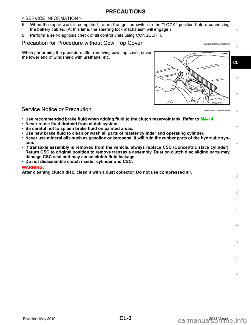
When performing the procedure after removing cowl top cover, cover
the lower end of windshield with urethane, etc.
Service Notice or PrecautionINFOID:0000000005928990
•Use recommended brake fluid when adding fluid to the clutch reservoir tank. Refer to MA-14.
• Never reuse fluid drained from clutch system.
• Be careful not to splash brake fluid on painted areas.
• Use new brake fluid to clean or wash all part s of master cylinder and operating cylinder.
• Never use mineral oils such as gasoline or kerosene. It will ruin the rubber parts of the hydraulic sys-
tem.
• If transaxle assembly is removed from the vehicle, always replace CSC (Con centric slave cylinder).
Return CSC to original position to remove transaxle assembly. Dust on clutch disc sliding parts may
damage CSC seal and may cause clutch fluid leakage.
• Do not disassemble clutch master cylinder and CSC.
WARNING:
After cleaning clutch disc, cl ean it with a dust collector. Do not use compressed air.
PIIB3706J
Revision: May 2010 2011 Versa
Page 1008 of 3787
![NISSAN TIIDA 2011 Service Manual PDF CO-8
< SYMPTOM DIAGNOSIS >[HR16DE]
OVERHEATING CAUSE ANALYSIS
Except cool-
ing system
parts mal-
function—
Overload on engine Abusive driving
High engine rpm under no
load
Driving in low gear for](/img/5/57396/w960_57396-1007.png "NISSAN TIIDA 2011 Service Manual PDF CO-8
< SYMPTOM DIAGNOSIS >[HR16DE]
OVERHEATING CAUSE ANALYSIS
Except cool-
ing system
parts mal-
function—
Overload on engine Abusive driving
High engine rpm under no
load
Driving in low gear for")
CO-8
< SYMPTOM DIAGNOSIS >[HR16DE]
OVERHEATING CAUSE ANALYSIS
Except cool-
ing system
parts mal-
function—
Overload on engine Abusive driving
High engine rpm under no
load
Driving in low gear for ex-
tended time
Driving at extremely high
speed
Power train system mal-
function
—
Installed improper size
wheels and tires
Dragging brakes
Improper ignition timing
Blocked or restricted air
flow Blocked bumper
Installed front bumper fas-
cia cover
—
Blocked radiator grille Mud contamination or paper
clogging
Blocked radiator Blocked air flow
Blocked condenser
Installed large fog lamp
Symptom
Check items
Revision: May 2010 2011 Versa
Page 1033 of 3787
![NISSAN TIIDA 2011 Service Manual PDF OVERHEATING CAUSE ANALYSISCO-33
< SERVICE INFORMATION > [MR18DE]
C
D
E
F
G H
I
J
K L
M A
CO
NP
O
Except cool-
ing system
parts mal-
function —
Overload on engine Abusive driving
High engine rpm und](/img/5/57396/w960_57396-1032.png "NISSAN TIIDA 2011 Service Manual PDF OVERHEATING CAUSE ANALYSISCO-33
< SERVICE INFORMATION > [MR18DE]
C
D
E
F
G H
I
J
K L
M A
CO
NP
O
Except cool-
ing system
parts mal-
function —
Overload on engine Abusive driving
High engine rpm und")
OVERHEATING CAUSE ANALYSISCO-33
< SERVICE INFORMATION > [MR18DE]
C
D
E
F
G H
I
J
K L
M A
CO
NP
O
Except cool-
ing system
parts mal-
function —
Overload on engine Abusive driving
High engine rpm under no
load
Driving in low gear for ex-
tended time
Driving at extremely high
speed
Power train system mal-
function
—
Installed improper size
wheels and tires
Dragging brakes
Improper ignition timing
Blocked or restricted air
flow Blocked bumper
Installed front bumper fas-
cia cover
—
Blocked radiator grille Mud contamination or paper
clogging
Blocked radiator Blocked air flow
Blocked condenser
Installed large fog lamp
Symptom
Check items
Revision: May 2010 2011 Versa
Page 1042 of 3787
![NISSAN TIIDA 2011 Service Manual PDF CO-42
< SERVICE INFORMATION >[MR18DE]
RADIATOR
• Warm up engine thoroughly to make sure there is no leakage of fuel, exhaust gas, or any oils/fluids including
engine oil and engine coolant.
• Blee](/img/5/57396/w960_57396-1041.png "NISSAN TIIDA 2011 Service Manual PDF CO-42
< SERVICE INFORMATION >[MR18DE]
RADIATOR
• Warm up engine thoroughly to make sure there is no leakage of fuel, exhaust gas, or any oils/fluids including
engine oil and engine coolant.
• Blee")
CO-42
< SERVICE INFORMATION >[MR18DE]
RADIATOR
• Warm up engine thoroughly to make sure there is no leakage of fuel, exhaust gas, or any oils/fluids including
engine oil and engine coolant.
• Bleed air from passages in lines and hoses, such as in cooling system.
• After cooling down engine, again check oil/fluid levels including engine oil and engine coolant. Refill to spec-
ified level, if necessary.
• Summary of the inspection items:
*Power steering fluid, brake fluid, etc. Item
Before starting engine Engine runningAfter engine stopped
Engine coolant LevelLeakage Level
Engine oil LevelLeakage Level
Transmission/
transaxle fluid A/T and CVT Models
LeakageLevel/Leakage Leakage
M/T Models Level/Leakage LeakageLevel/Leakage
Other oils and fluids* LevelLeakage Level
Fuel LeakageLeakage Leakage
Exhaust gas —Leakage —
Revision: May 2010 2011 Versa
Page 1054 of 3787
![NISSAN TIIDA 2011 Service Manual PDF CO-54
< SERVICE INFORMATION >[MR18DE]
WATER OUTLET AND WATER CONTROL VALVE
• Warm up engine thoroughly to make sure there is no leakage of fuel, exhaust gas, or any oils/fluids including
engine oil](/img/5/57396/w960_57396-1053.png "NISSAN TIIDA 2011 Service Manual PDF CO-54
< SERVICE INFORMATION >[MR18DE]
WATER OUTLET AND WATER CONTROL VALVE
• Warm up engine thoroughly to make sure there is no leakage of fuel, exhaust gas, or any oils/fluids including
engine oil")
CO-54
< SERVICE INFORMATION >[MR18DE]
WATER OUTLET AND WATER CONTROL VALVE
• Warm up engine thoroughly to make sure there is no leakage of fuel, exhaust gas, or any oils/fluids including
engine oil and engine coolant.
• Bleed air from passages in lines and hoses, such as in cooling system.
• After cooling down engine, again check oil/fluid levels including engine oil and engine coolant. Refill to spec-
ified level, if necessary.
• Summary of the inspection items:
*Power steering fluid, brake fluid, etc. Item
Before starting engine Engine runningAfter engine stopped
Engine coolant LevelLeakage Level
Engine oil LevelLeakage Level
Transmission/
transaxle fluid A/T and CVT Models
LeakageLevel/Leakage Leakage
M/T Models Level/Leakage LeakageLevel/Leakage
Other oils and fluids* LevelLeakage Level
Fuel LeakageLeakage Leakage
Exhaust gas —Leakage —
Revision: May 2010 2011 Versa
Page 1059 of 3787

CVT-4
CONSULT-III Reference Value in Data Monitor
Mode .................................................................... ..
135
Wiring Diagram - CVT - ODSW .............................136
Diagnosis Procedure .............................................136
Component Inspection ...........................................138
SHIFT POSITION INDICATOR CIRCUIT ........140
Description ........................................................... ..140
CONSULT-III Reference Value in Data Monitor
Mode .................................................................... ..
140
Diagnosis Procedure .............................................140
TROUBLE DIAGNOSIS FOR SYMPTOMS .....141
Wiring Diagram - CVT - NONDTC ....................... ..141
O/D OFF Indicator Lamp Does Not Come On .......143
Engine Cannot Be Started in "P" and "N" Position ..145
In "P" Position, Vehicle Moves Forward or Back-
ward When Pushed ...............................................
145
In "N" Position, Vehicle Moves ............................ ..146
Large Shock "N" → "R" Position .......................... ..146
Vehicle Does Not Creep Backward in "R" Position ..147
Vehicle Does Not Creep Forward in "D" or "L" Po-
sition ......................................................................
148
Vehicle Speed Does Not Change in "L" Position ...149
Vehicle Speed Does Not Change in overdrive-off
mode ......................................................................
150
Vehicle Speed Does Not Change in "D" Position ..151
Vehicle Does Not Decelerate by Engine Brake .....151
CVT SHIFT LOCK SYSTEM ........................... .153
Description ........................................................... ..153
Shift Lock System Electrical Parts Location ..........154
Wiring Diagram - CVT - SHIFT ..............................155
Diagnosis Procedure .............................................155
TCM ..................................................................159
Removal and Installation ..................................... ..159
SHIFT CONTROL SYSTEM ............................160
Removal and Installation ..................................... ..160
CVT Shift Selector Disassembly and Assembly ....163
Shift Selector Handle Removal and Installation ....163
Adjustment of CVT Position ................................. ..164
Checking of CVT Position ......................................164
KEY INTERLOCK CABLE ...............................166
Removal and Installation ..................................... ..166
PRIMARY SPEED SENSOR ...........................169
Exploded View ..................................................... ..169
Removal and Installation .......................................169
Inspection ............................................................. .169
SECONDARY SPEED SENSOR ......................170
Exploded View ..................................................... .170
Removal and Installation .......................................170
Inspection ............................................................. .170
AIR BREATHER HOSE ....................................171
Removal and Installation .......................................171
OIL PAN .......................................................... ..172
Exploded View ..................................................... .172
Removal and Installation .......................................172
Inspection ............................................................. .173
DIFFERENTIAL SIDE OIL SEAL .....................174
Removal and Installation .......................................174
CVT OIL WARMER SYSTEM ......................... ..175
WATER HOSE ........................................................ .175
WATER HOSE : Exploded View ...........................175
WATER HOSE : Removal and Installation ...........175
WATER HOSE : Inspection ..................................176
CVT FLUID COOLER HOSE .................................. .176
CVT FLUID COOLER HOSE : Exploded View .....177
CVT FLUID COOLER HOSE : Removal and In-
stallation ................................................................
177
CVT FLUID COOLER HOSE : Inspection .............179
CVT OIL WARMER ................................................ .179
CVT OIL WARMER : Exploded View ....................179
CVT OIL WARMER : Removal and Installation ....179
CVT OIL WARMER : Inspection .......................... .179
TRANSAXLE ASSEMBLY ...............................180
Removal and Installation .......................................180
SERVICE DATA AND SPECIFICATIONS
(SDS) .............................................................. ..
183
General Specification ........................................... .183
Vehicle Speed When Shifting Gears .....................183
Stall Speed ............................................................183
Line Pressure ........................................................183
Solenoid Valves ....................................................184
CVT Fluid Temperature Sensor ............................184
Primary Speed Sensor ..........................................184
Secondary Speed Sensor .................................... .184
Removal and Installation .......................................184
Revision: May 2010 2011 Versa