clock NISSAN TIIDA 2011 Service Service Manual
[x] Cancel search | Manufacturer: NISSAN, Model Year: 2011, Model line: TIIDA, Model: NISSAN TIIDA 2011Pages: 3787, PDF Size: 78.35 MB
Page 2558 of 3787
![NISSAN TIIDA 2011 Service Service Manual EM-168
< SERVICE INFORMATION >[MR18DE]
TIMING CHAIN
• Make sure O-ring on cylinder block is correctly installed.
• Be careful not to damage front oil seal by
interference with front end of cranks NISSAN TIIDA 2011 Service Service Manual EM-168
< SERVICE INFORMATION >[MR18DE]
TIMING CHAIN
• Make sure O-ring on cylinder block is correctly installed.
• Be careful not to damage front oil seal by
interference with front end of cranks](/img/5/57396/w960_57396-2557.png)
EM-168
< SERVICE INFORMATION >[MR18DE]
TIMING CHAIN
• Make sure O-ring on cylinder block is correctly installed.
• Be careful not to damage front oil seal by
interference with front end of crankshaft.
15. Install front cover, and tighten bolts in two stages to specified torque in numerical order as shown.
CAUTION:
• Attaching should be done within 5 minutes after liquidgasket application.
• Be sure to wipe off any excessive liquid gasket leaking.
NOTE:
Installation position of bolts is as shown.
16. Install crankshaft pulley using the following procedure.
a. Install crankshaft pulley. CAUTION:
• Never damage front oil seal lip section.
• If needed use a plastic hammer, tap on its center portion (not circumference) to seat crankshaft
pulley.
b. Apply new engine oil to thread and seat surfaces of crankshaft pulley bolt.
c. Secure crankshaft pulley (1) using Tool (A).
d. Tighten crankshaft pulley bolt in two steps.
• For angle tightening, put a paint mark (B) on crankshaft pulley(2), matching with any one of six easy to recognize angle
marks (A) on crankshaft pulley bolt flange (1).
• Turn 60 degrees clockwise (angle tightening).
• Check the tightening angle with movement of one angle mark.
e. Make sure that crankshaft rotates clockwise smoothly.
17. Installation of the remaining components is in the reverse order of removal.
M6 bolts : No. 1
M10 bolts : No. 6, 7, 10, 11, 14
M12 bolts : No. 2, 4, 8, 12
M8 bolts : Except the above
PBIC3164J
Tool Number : KV10109300 ( — )
Step 1 : 29.4 N·m (3.0 kg-m, 22 ft-lb)
Step 2 : 60° clockwise
PBIC3961E
PBIC3963E
Revision: May 2010 2011 Versa
Page 2566 of 3787
![NISSAN TIIDA 2011 Service Service Manual EM-176
< SERVICE INFORMATION >[MR18DE]
CAMSHAFT
5. Install camshaft bracket bolts in three stage in numerical order
as shown.
• There are two types of bolts. Locate the bolts as shown.
6. Tighten al NISSAN TIIDA 2011 Service Service Manual EM-176
< SERVICE INFORMATION >[MR18DE]
CAMSHAFT
5. Install camshaft bracket bolts in three stage in numerical order
as shown.
• There are two types of bolts. Locate the bolts as shown.
6. Tighten al](/img/5/57396/w960_57396-2565.png)
EM-176
< SERVICE INFORMATION >[MR18DE]
CAMSHAFT
5. Install camshaft bracket bolts in three stage in numerical order
as shown.
• There are two types of bolts. Locate the bolts as shown.
6. Tighten all bolts in numerical order in three steps.
7. Install the camshaft sprocket (INT) (2) to the camshaft (INT). NOTE:
Align the matching mark (A) applied during removal. Securely
align the knock pin and the pin hole, and then install them.
8. Tighten camshaft (INT) sprocket bolt. NOTE:
Secure the hexagonal part of camshaft (INT) using wrench to tighten bolt.
9. Turn 67 degrees clockwise (angle tightening) using Tool (B).
CAUTION:
Never judge by visual inspect ion without an angle wrench.
: Engine front
M6 bolts [thread length: 57.5 mm (2.264 in)]
: 13, 14 and 15
M6 bolts [thread length: 35.00 mm (1.378 in)] : Except the above
Step 1 : 1.96 N·m (0.20 kg-m, 17 in-lb)
Step 2 : 5.88 N·m (0.60 kg-m, 52 in-lb)
Step 3 : 9.5 N·m (0.97 kg-m, 84 in-lb)
1 : Camshaft bracket : Engine front
PBIC3176J
PBIC3992J
Camshaft sprocket bolt (INT) : 35.0 N·m (3.6 kg-m, 26 ft-lb)
1 : Camshaft sprocket (INT)
A : Camshaft (INT) hexagonal part
Tool number : KV10112100 (BT-8653-A)
PBIC3455J
Revision: May 2010 2011 Versa
Page 2568 of 3787
![NISSAN TIIDA 2011 Service Service Manual EM-178
< SERVICE INFORMATION >[MR18DE]
CAMSHAFT
4. Clean the mating area of intake valve timing control solenoid
valve. Insert a clean shop cloth (with no oil adhesion) into the oil
hole (A) of the cy NISSAN TIIDA 2011 Service Service Manual EM-178
< SERVICE INFORMATION >[MR18DE]
CAMSHAFT
4. Clean the mating area of intake valve timing control solenoid
valve. Insert a clean shop cloth (with no oil adhesion) into the oil
hole (A) of the cy](/img/5/57396/w960_57396-2567.png)
EM-178
< SERVICE INFORMATION >[MR18DE]
CAMSHAFT
4. Clean the mating area of intake valve timing control solenoid
valve. Insert a clean shop cloth (with no oil adhesion) into the oil
hole (A) of the cylinder head.
5. Install engine mounting bracket (RH), engine mounting insulator, and torque rod (RH) under the Step 4 condition. (With intake
valve timing control solenoid valve removed, and a shop cloth
inserted into the oil hole.) Refer to EM-197, "
Component".
6. Crank engine, and then make sure that engine oil comes out from intake valve timing control solenoid valve hole (A). End cranking after checking.
• Check engine oil leakage by oil amount adhered to the shop cloth inserted into the oil hole.
WARNING:
• Be careful not to touch rotating parts (drive be lts, idler pulley, and crankshaft pulley, etc.).
• Prevent splashing by using a shop cloth so as to prevent the worker from injury from engine oil
and so as to prevent engi ne oil contamination.
CAUTION:
• Do not perform cranking without installing right engine mount bracket, right engine mount insu-
lator, and right torque rod.
• Prevent splashing by using a shop cloth so as to prevent engine oil from being splashed to
engine and vehicle. Especially, be careful not to apply engine oil to rubber parts of drive belts,
engine mounting insulator, etc. Wipe engi ne oil off immediately if it is splashed.
7. Perform the following inspection if engine oil does not come out from intake valve timing control solenoid valve oil hole of the cylinder head.
• Remove oil filter (for intake valve timing control), and then clean it. Refer to EM-202, "
Component".
• Clean oil groove between oil strainer and intake valve timing control solenoid valve. Refer to LU-16
.
8. Remove components between intake valve timing c ontrol solenoid valve and camshaft sprocket (INT),
and then check each oil groove for clogging.
• Clean oil groove if necessary. Refer to LU-16
.
9. Installation of the remaining components is in the reverse order of removal
Valve ClearanceINFOID:0000000005931020
INSPECTION
Perform inspection as follows after removal, installation or replacement of camshaft or valve-related parts, or if
there is unusual engine conditions regarding valve clearance.
1. Remove rocker cover. Refer to EM-151
.
2. Measure the valve clearance with the following procedure:
a. Set No. 1 cylinder at TDC of its compression stroke. • Rotate crankshaft pulley (1) clockwise and align TDC mark (no paint) (B) to timing indicator (A) on front
cover.
1 : Front cover
:Vehicle front
WBIA0781E
C : White paint mark (Not use for service)
PBIC3960E
Revision: May 2010 2011 Versa
Page 2579 of 3787
![NISSAN TIIDA 2011 Service Service Manual CYLINDER HEADEM-189
< SERVICE INFORMATION > [MR18DE]
C
D
E
F
G H
I
J
K L
M A
EM
NP
O
INSPECTION AFTER REMOVAL
Cylinder Head Bolts Outer Diameter
• Cylinder head bolts are tightened by plastic zone t NISSAN TIIDA 2011 Service Service Manual CYLINDER HEADEM-189
< SERVICE INFORMATION > [MR18DE]
C
D
E
F
G H
I
J
K L
M A
EM
NP
O
INSPECTION AFTER REMOVAL
Cylinder Head Bolts Outer Diameter
• Cylinder head bolts are tightened by plastic zone t](/img/5/57396/w960_57396-2578.png)
CYLINDER HEADEM-189
< SERVICE INFORMATION > [MR18DE]
C
D
E
F
G H
I
J
K L
M A
EM
NP
O
INSPECTION AFTER REMOVAL
Cylinder Head Bolts Outer Diameter
• Cylinder head bolts are tightened by plastic zone tightening
method. Whenever the size difference between (d1) and (d2)
exceeds the limit, replac e them with a new one.
• If reduction of outer diameter appear s in a position other than (d2),
use it as (d2) point.
Cylinder Head Distortion
NOTE:
When performing this inspection, cylinder block distortion should be also checked. Refer to EM-219, "
Inspec-
tion After Disassembly".
1. Wipe off engine oil and remove water scale (like deposit ), gasket, sealant, carbon, etc. with a scraper.
CAUTION:
Never allow gasket debris to enter passag es for engine oil or engine coolant.
2. At each of several locations on bottom surface of cylinder head, measure the distortion in six di rections using straightedge (A)
and feeler gauge (B).
• If it exceeds the limit, replace cylinder head.
INSTALLATION
1. Install cylinder head gasket.
2. Apply new engine oil to threads and seating surface of bolts.
CAUTION:
If cylinder head bolts re-used, ch eck their outer diameters before installation. Follow the "Cylinder
Head Bolts Outer Diameter" procedure.
3. Install cylinder head, follow the steps below to tighten cylinder head bolts in numerical order as shown.Limit [(d1) – (d2)]: 0.15 mm (0.0059 in)
PBIC3994E
Limit: 0.1 mm (0.004 in)
PBIC3207J
Step a : 40 N·m (4.1 kg-m, 30 ft-lb)
Step b : 100
° clockwise
Step c : Loosen to 0 N·m in the reverse order of tight- ening.
Step d : 40 N·m (4.1 kg-m, 30 ft-lb)
Step e : 100 ° clockwise
Step f : 100 ° clockwise
PBIC3206J
Revision: May 2010 2011 Versa
Page 2598 of 3787
![NISSAN TIIDA 2011 Service Service Manual EM-208
< SERVICE INFORMATION >[MR18DE]
CYLINDER BLOCK
15. Tighten main bearing cap bolts in two steps in numerical order
as shown.
CAUTION:
Measure the angle in step 2 us ing Tool (A). Do not measure
NISSAN TIIDA 2011 Service Service Manual EM-208
< SERVICE INFORMATION >[MR18DE]
CYLINDER BLOCK
15. Tighten main bearing cap bolts in two steps in numerical order
as shown.
CAUTION:
Measure the angle in step 2 us ing Tool (A). Do not measure](/img/5/57396/w960_57396-2597.png)
EM-208
< SERVICE INFORMATION >[MR18DE]
CYLINDER BLOCK
15. Tighten main bearing cap bolts in two steps in numerical order
as shown.
CAUTION:
Measure the angle in step 2 us ing Tool (A). Do not measure
visually.
• After installing bolts, make sure that crankshaft can be rotated smoothly by hand.
• Check crankshaft end play. Refer to EM-219, "
Inspection After Disassembly".
16. Using snap ring pliers, install new snap ri ng to the groove of the piston rear side.
• Insert it fully into groove to install.
17. Assemble piston to connecting rod. • Using a suitable tool, heat the piston until the pi ston pin can be pushed in by hand without excess force
[approximately 60 ° to 70 °C (140° to 158 °F)]. From the front to the rear, insert piston pin into piston and
connecting rod.
• Assemble so that the front mark (A) on the piston head and the oil hole (B) and the cylinder number (C) on connecting rod
are positioned as shown.
18. Install new snap ring to the groove of the piston front side. • Insert it fully into groove to install.
• After installing, make sure that connecting rod moves
smoothly.
19. Using a suitable tool, install piston rings. CAUTION:
• Be careful not to damage piston.
• Be careful not to damage piston rings by expanding them excessively.
: Engine front
PBIC3235J
Step 1 : 34.3 N·m (3.5 kg-m, 25 ft-lb)
Step 2 : 60° clockwise
Tool number : KV10112100 (BT-8653-A)
PBIC3240J
D : Big end diameter grade
E : Small end diameter grade
F : Front mark (connecting rod bearing cap)
PBIC3587J
Revision: May 2010 2011 Versa
Page 2600 of 3787
![NISSAN TIIDA 2011 Service Service Manual EM-210
< SERVICE INFORMATION >[MR18DE]
CYLINDER BLOCK
• Using Tool (A), install piston with the front mark on the piston
head facing the front of the engine.
CAUTION:
Be careful not to damage the c NISSAN TIIDA 2011 Service Service Manual EM-210
< SERVICE INFORMATION >[MR18DE]
CYLINDER BLOCK
• Using Tool (A), install piston with the front mark on the piston
head facing the front of the engine.
CAUTION:
Be careful not to damage the c](/img/5/57396/w960_57396-2599.png)
EM-210
< SERVICE INFORMATION >[MR18DE]
CYLINDER BLOCK
• Using Tool (A), install piston with the front mark on the piston
head facing the front of the engine.
CAUTION:
Be careful not to damage the cylinder wall and crankshaft
pin, resulting from an inte rference of the connecting rod
big end.
22. Install connecting rod cap. • Match the stamped cylinder number marks (C) on connectingrod with those on connecting rod cap to install.
23. Tighten connecting rod bolt with the following procedure: CAUTION:
• Make sure that there is no gap in the thrust surface (A) of
the joint between connecting rod (1) and connecting rod
bearing cap (2) and that th ese parts are in the correct
position. And then, tighten the connecting rod bolts.
• If the connecting rod bolts are reused, measure the outer
diameter. Refer to EM-219, "
Inspection After Disassem-
bly".
a. Apply new engine oil to the threads and seats of connecting rod bolts.
b. Tighten connecting rod bolts in two steps using Tool.
• After tightening connecting rod bolt, make sure that crankshaft rotates smoothly.
• Check the connecting rod side clearance. Refer to EM-219, "
Inspection After Disassembly".
24. Install oil pan (upper). Refer to EM-144
.
NOTE:
Install the rear oil seal after installing the oil pan (upper).
25. Install rear oil seal. Refer to EM-144
.
Tool number : EM03470000 (J-8037)
PBIC3244J
A : Front mark (piston)
B : Oil hole
D : Big end diameter grade
E : Small end diameter grade
F : Front mark (connecting rod bearing cap)
PBIC3587J
Step 1 : 19.6 N·m (2.0 kg-m, 14 ft-lb)
Step 2 : 60
° clockwise
Tool number : KV10112100 (BT-8653-A)
PBIC3510J
Revision: May 2010 2011 Versa
Page 2673 of 3787

FL-6
< SERVICE INFORMATION >
FUEL LEVEL SENSOR UNIT, FUEL FILTER AND FUEL PUMP ASSEMBLY
FUEL LEVEL SENSOR UNIT, FUEL FILTER AND FUEL PUMP ASSEMBLY
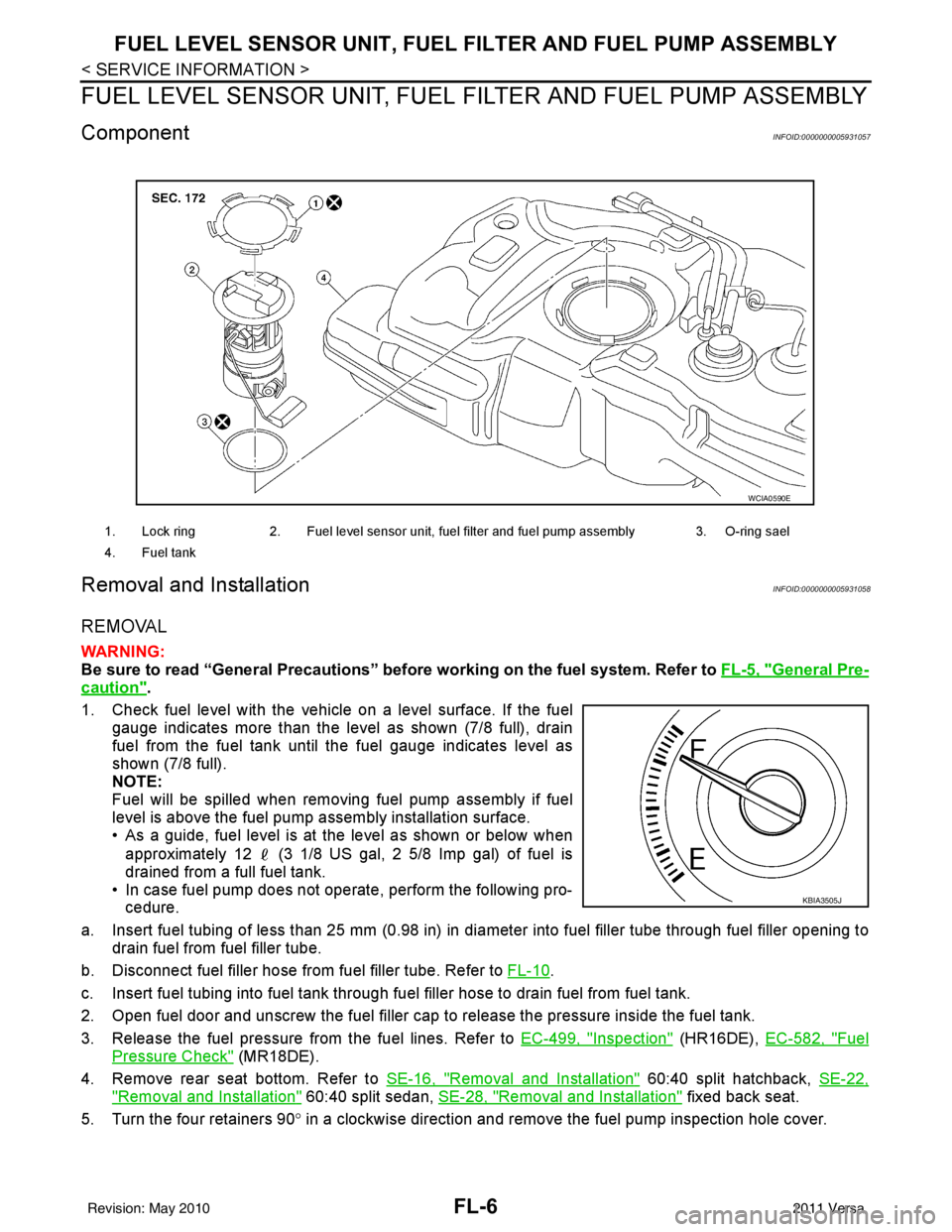
ComponentINFOID:0000000005931057
Removal and InstallationINFOID:0000000005931058
REMOVAL
WARNING:
Be sure to read “General Precautions” be fore working on the fuel system. Refer to FL-5, "
General Pre-
caution".
1. Check fuel level with the vehicle on a level surface. If the fuel gauge indicates more than the level as shown (7/8 full), drain
fuel from the fuel tank until the fuel gauge indicates level as
shown (7/8 full).
NOTE:
Fuel will be spilled when removing fuel pump assembly if fuel
level is above the fuel pump assembly installation surface.
• As a guide, fuel level is at the level as shown or below when
approximately 12 (3 1/8 US gal, 2 5/8 Imp gal) of fuel is
drained from a full fuel tank.
• In case fuel pump does not operate, perform the following pro- cedure.
a. Insert fuel tubing of less than 25 mm (0.98 in) in di ameter into fuel filler tube through fuel filler opening to
drain fuel from fuel filler tube.
b. Disconnect fuel filler hose from fuel filler tube. Refer to FL-10
.
c. Insert fuel tubing into fuel tank through f uel filler hose to drain fuel from fuel tank.
2. Open fuel door and unscrew the fuel filler cap to release the pressure inside the fuel tank.
3. Release the fuel pressure from the fuel lines. Refer to EC-499, "
Inspection" (HR16DE), EC-582, "Fuel
Pressure Check" (MR18DE).
4. Remove rear seat bottom. Refer to SE-16, "
Removal and Installation" 60:40 split hatchback, SE-22,
"Removal and Installation" 60:40 split sedan, SE-28, "Removal and Installation" fixed back seat.
5. Turn the four retainers 90 ° in a clockwise direction and remove the fuel pump inspection hole cover.
1. Lock ring 2. Fuel level sensor unit, fuel filter and fuel pump assembly 3. O-ring sael
4. Fuel tank
WCIA0590E
KBIA3505J
Revision: May 2010 2011 Versa
Page 2675 of 3787

FL-8
< SERVICE INFORMATION >
FUEL LEVEL SENSOR UNIT, FUEL FILTER AND FUEL PUMP ASSEMBLY
INSPECTION AFTER REMOVAL
Make sure that the fuel level sensor unit, fuel filter and fuel pump is free from defects and foreign materials.
INSTALLATION
Installation is in the reverse order of removal.
Fuel Level Sensor Unit, Fuel Filter and Fuel Pump Assembly
1. Install O-ring seal to fuel tank without twisting.
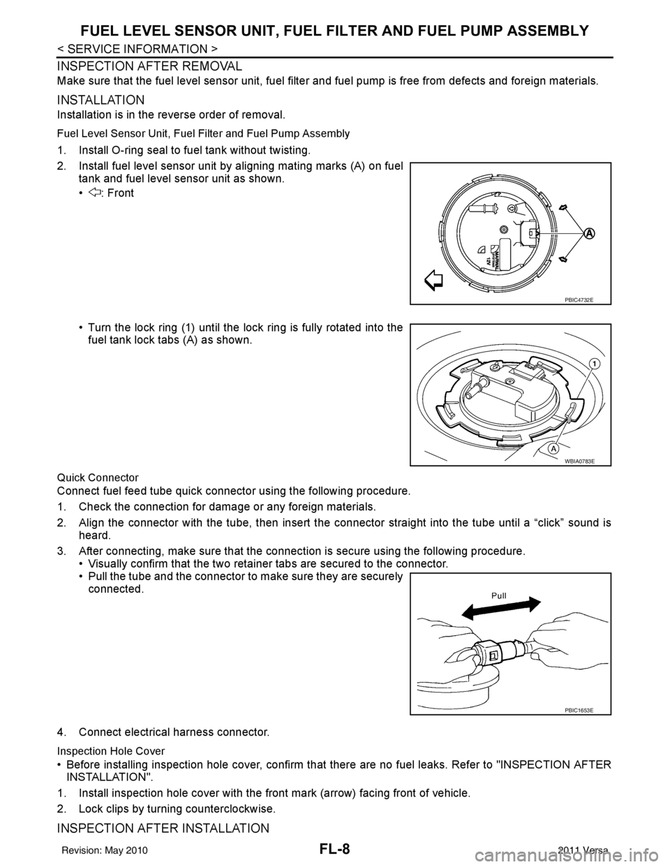
2. Install fuel level sensor unit by aligning mating marks (A) on fuel
tank and fuel level sensor unit as shown.
• : Front
• Turn the lock ring (1) until the lock ring is fully rotated into thefuel tank lock tabs (A) as shown.
Quick Connector
Connect fuel feed tube quick connector using the following procedure.
1. Check the connection for damage or any foreign materials.
2. Align the connector with the tube, then insert the connector straight into the tube until a “click” sound is heard.
3. After connecting, make sure that the connec tion is secure using the following procedure.
• Visually confirm that the two retainer tabs are secured to the connector.
• Pull the tube and the connector to make sure they are securely connected.
4. Connect electrical harness connector.
Inspection Hole Cover
• Before installing inspection hole cover, confirm that there are no fuel leaks. Refer to "INSPECTION AFTER
INSTALLATION".
1. Install inspection hole cover with the front mark (arrow) facing front of vehicle.
2. Lock clips by turning counterclockwise.
INSPECTION AFTER INSTALLATION
PBIC4732E
WBIA0783E
PBIC1653E
Revision: May 2010 2011 Versa
Page 2677 of 3787

FL-10
< SERVICE INFORMATION >
FUEL TANK
FUEL TANK
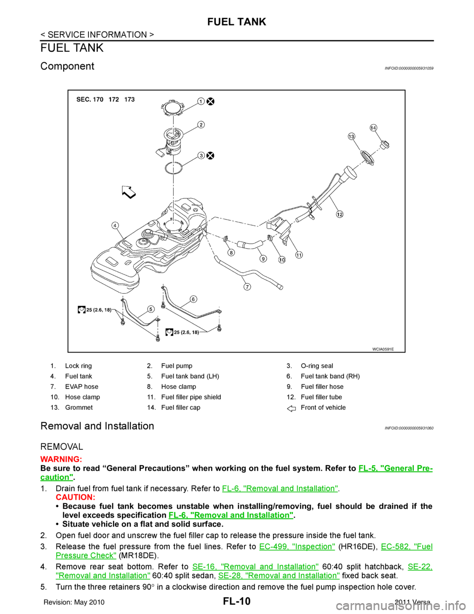
ComponentINFOID:0000000005931059
Removal and InstallationINFOID:0000000005931060
REMOVAL
WARNING:
Be sure to read “General Precautions” when working on the fuel system. Refer to FL-5, "
General Pre-
caution".
1. Drain fuel from fuel tank if necessary. Refer to FL-6, "
Removal and Installation".
CAUTION:
• Because fuel tank becomes unstable when installing/removing, fuel should be drained if the
level exceeds specification FL-6, "
Removal and Installation".
• Situate vehicle on a flat and solid surface.
2. Open fuel door and unscrew the fuel filler cap to release the pressure inside the fuel tank.
3. Release the fuel pressure from the fuel lines. Refer to EC-499, "
Inspection" (HR16DE), EC-582, "Fuel
Pressure Check" (MR18DE).
4. Remove rear seat bottom. Refer to SE-16, "
Removal and Installation" 60:40 split hatchback, SE-22,
"Removal and Installation" 60:40 split sedan, SE-28, "Removal and Installation" fixed back seat.
5. Turn the three retainers 90 ° in a clockwise direction and remove the fuel pump inspection hole cover.
1. Lock ring 2. Fuel pump 3. O-ring seal
4. Fuel tank 5. Fuel tank band (LH) 6. Fuel tank band (RH)
7. EVAP hose 8. Hose clamp 9. Fuel filler hose
10. Hose clamp 11. Fuel filler pipe shield 12. Fuel filler tube
13. Grommet 14. Fuel filler cap Front of vehicle
WCIA0591E
Revision: May 2010 2011 Versa
Page 2683 of 3787

FL-16
< SERVICE INFORMATION >
EVAPORATIVE EMISSION SYSTEM
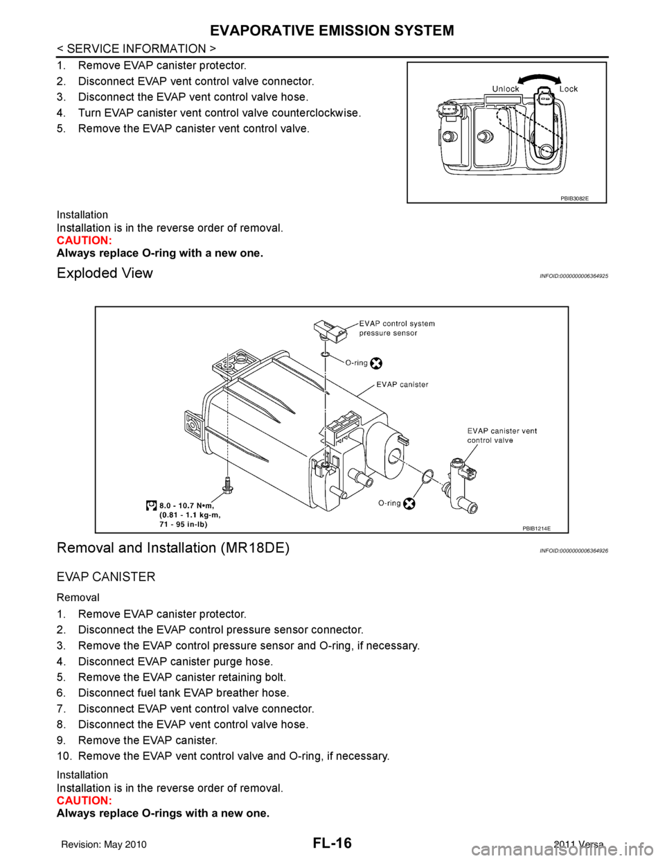
1. Remove EVAP canister protector.
2. Disconnect EVAP vent control valve connector.
3. Disconnect the EVAP vent control valve hose.
4. Turn EVAP canister vent control valve counterclockwise.
5. Remove the EVAP canister vent control valve.
Installation
Installation is in the reverse order of removal.
CAUTION:
Always replace O-ring with a new one.
Exploded ViewINFOID:0000000006364925
Removal and Installation (MR18DE)INFOID:0000000006364926
EVAP CANISTER
Removal
1. Remove EVAP canister protector.
2. Disconnect the EVAP control pressure sensor connector.
3. Remove the EVAP control pressure sensor and O-ring, if necessary.
4. Disconnect EVAP canister purge hose.
5. Remove the EVAP canister retaining bolt.
6. Disconnect fuel tank EVAP breather hose.
7. Disconnect EVAP vent control valve connector.
8. Disconnect the EVAP vent control valve hose.
9. Remove the EVAP canister.
10. Remove the EVAP vent control valve and O-ring, if necessary.
Installation
Installation is in the reverse order of removal.
CAUTION:
Always replace O-rings with a new one.
PBIB3082E
PBIB1214E
Revision: May 20102011 Versa