clock NISSAN TIIDA 2011 Service Workshop Manual
[x] Cancel search | Manufacturer: NISSAN, Model Year: 2011, Model line: TIIDA, Model: NISSAN TIIDA 2011Pages: 3787, PDF Size: 78.35 MB
Page 2684 of 3787
EVAPORATIVE EMISSION SYSTEMFL-17
< SERVICE INFORMATION >
C
DE
F
G H
I
J
K L
M A
FL
NP
O
EVAP CANISTER CONTROL PRESSURE SENSOR
Removal
1. Remove EVAP canister protector.
2. Disconnect the EVAP control pressure sensor connector.
3. Remove the EVAP canister control pressure sensor and O-ring.
Installation
Installation is in the reverse order of removal.
CAUTION:
Always replace O-ring with a new one.
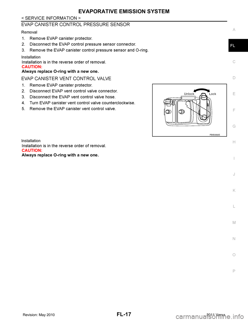
EVAP CANISTER VENT CONTROL VALVE
1. Remove EVAP canister protector.
2. Disconnect EVAP vent control valve connector.
3. Disconnect the EVAP vent control valve hose.
4. Turn EVAP canister vent control valve counterclockwise.
5. Remove the EVAP canister vent control valve.
Installation
Installation is in the reverse order of removal.
CAUTION:
Always replace O-ring with a new one.
PBIB3082E
Revision: May 2010
2011 Versa
Page 2760 of 3787
GW-6
< SERVICE INFORMATION >
SQUEAK AND RATTLE TROUBLE DIAGNOSES
SQUEAK AND RATTLE TROUBLE DIAGNOSES
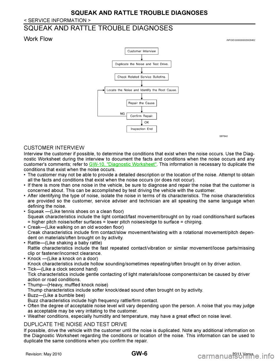
Work FlowINFOID:0000000005929462
CUSTOMER INTERVIEW
Interview the customer if possible, to determine the conditions that exist when the noise occurs. Use the Diag-
nostic Worksheet during the interview to document the facts and conditions when the noise occurs and any
customer's comments; refer to GW-10, "
Diagnostic Worksheet". This information is necessary to duplicate the
conditions that exist when the noise occurs.
• The customer may not be able to provide a detailed description or the location of the noise. Attempt to obtain all the facts and conditions that exist w hen the noise occurs (or does not occur).
• If there is more than one noise in the vehicle, be sure to diagnose and repair the noise that the customer is
concerned about. This can be accomplished by test driving the vehicle with the customer.
• After identifying the type of noise, isolate the noise in terms of its characteristics. The noise characteristics
are provided so the customer, service adviser and technician are all speaking the same language when
defining the noise.
• Squeak —(Like tennis shoes on a clean floor)
Squeak characteristics include the light contact/fast movement/brought on by road conditions/hard surfaces
= higher pitch noise/softer surfaces = lower pitch noises/edge to surface = chirping.
• Creak—(Like walking on an old wooden floor)
Creak characteristics include firm contact/slow mo vement/twisting with a rotational movement/pitch depen-
dent on materials/often brought on by activity.
• Rattle—(Like shaking a baby rattle)
Rattle characteristics include the fast repeated contac t/vibration or similar movement/loose parts/missing
clip or fastener/incorrect clearance.
• Knock —(Like a knock on a door)
Knock characteristics include hollow sounding/someti mes repeating/often brought on by driver action.
• Tick—(Like a clock second hand) Tick characteristics include gentle contacting of light materials/loose components/can be caused by driver
action or road conditions.
• Thump—(Heavy, muffled knock noise) Thump characteristics include softer k nock/dead sound often brought on by activity.
• Buzz—(Like a bumble bee)
Buzz characteristics include hi gh frequency rattle/firm contact.
• Often the degree of acceptable noise level will vary depending upon the person. A noise that you may judge as acceptable may be very irritating to the customer.
• Weather conditions, especially humidity and temperat ure, may have a great effect on noise level.
DUPLICATE THE NOISE AND TEST DRIVE
If possible, drive the vehicle with the customer until the noise is duplicated. Note any additional information on
the Diagnostic Worksheet regarding the conditions or lo cation of the noise. This information can be used to
duplicate the same conditions when you confirm the repair.
SBT842
Revision: May 2010 2011 Versa
Page 2826 of 3787
SQUEAK AND RATTLE TROUBLE DIAGNOSESIP-5
< SYMPTOM DIAGNOSIS >
C
DE
F
G H
J
K L
M A
B
IP
N
O P
SYMPTOM DIAGNOSIS
SQUEAK AND RATTLE TROUBLE DIAGNOSES
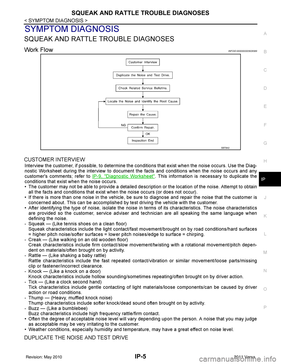
Work FlowINFOID:0000000005929589
CUSTOMER INTERVIEW
Interview the customer, if possible, to determine the c onditions that exist when the noise occurs. Use the Diag-
nostic Worksheet during the interv iew to document the facts and conditions when the noise occurs and any
customer's comments; refer to IP-9, "
Diagnostic Worksheet". This information is necessary to duplicate the
conditions that exist when the noise occurs.
• The customer may not be able to provide a detailed descr iption or the location of the noise. Attempt to obtain
all the facts and conditions that exist when the noise occurs (or does not occur).
• If there is more than one noise in the vehicle, be sure to diagnose and repair the noise that the customer is
concerned about. This can be accomplished by te st driving the vehicle with the customer.
• After identifying the type of noise, isolate the noise in terms of its characteristics. The noise characteristics are provided so the customer, service adviser and technician are all speaking the same language when
defining the noise.
- Squeak — (Like tennis shoes on a clean floor) Squeak characteristics include the light contact/fast movement/brought on by road conditions/hard surfaces
= higher pitch noise/softer surfaces = lower pitch noises/edge to surface = chirping.
- Creak — (Like walking on an old wooden floor) Creak characteristics include firm contact/slow mo vement/twisting with a rotational movement/pitch depen-
dent on materials/often brought on by activity.
- Rattle — (Like shaking a baby rattle) Rattle characteristics include the fast repeated contac t/vibration or similar movement/loose parts/missing
clip or fastener/incorrect clearance.
- Knock — (Like a knock on a door) Knock characteristics include hollow sounding/someti mes repeating/often brought on by driver action.
- Tick — (Like a clock second hand) Tick characteristics include gentle contacting of li ght materials/loose components/can be caused by driver
action or road conditions.
- Thump — (Heavy, muffled knock noise)
Thump characteristics include softer k nock/dead sound often brought on by activity.
- Buzz — (Like a bumblebee) Buzz characteristics include high frequency rattle/firm contact.
• Often the degree of acceptable noise level will vary depending upon the person. A noise that you may judge as acceptable may be very irritating to the customer.
• Weather conditions, especially humidity and temperature, may have a great effect on noise level.
DUPLICATE THE NOISE AND TEST DRIVE
SBT842
Revision: May 2010 2011 Versa
Page 3057 of 3787
HEADLAMP (FOR USA)LT-25
< SERVICE INFORMATION >
C
DE
F
G H
I
J
L
M A
B
LT
N
O P
2. Turn bulb socket counterclockwise and unlock from the front combination lamp assembly.
3. Remove bulb from its socket.
FRONT TURN SIGNAL LAMP
1. Turn lighting switch OFF.
2. Turn bulb socket counterclockwise and unlock from the front combination lamp assembly.
3. Remove bulb from its socket.
Removal and InstallationINFOID:0000000005929047
REMOVAL
1. Disconnect the negative battery terminal.
2. Remove front bumper fascia. Refer to EI-15
.
3. Remove front combination lamp assembly bolts (A).
4. Pull front combination lamp assembly (1) toward the vehicle front, disconnect connector, and remove assembly.
INSTALLATION
Installation is in the reverse order of removal.
• After installation, perform aiming adjustment. Refer to LT-23, "
Aiming Adjustment".
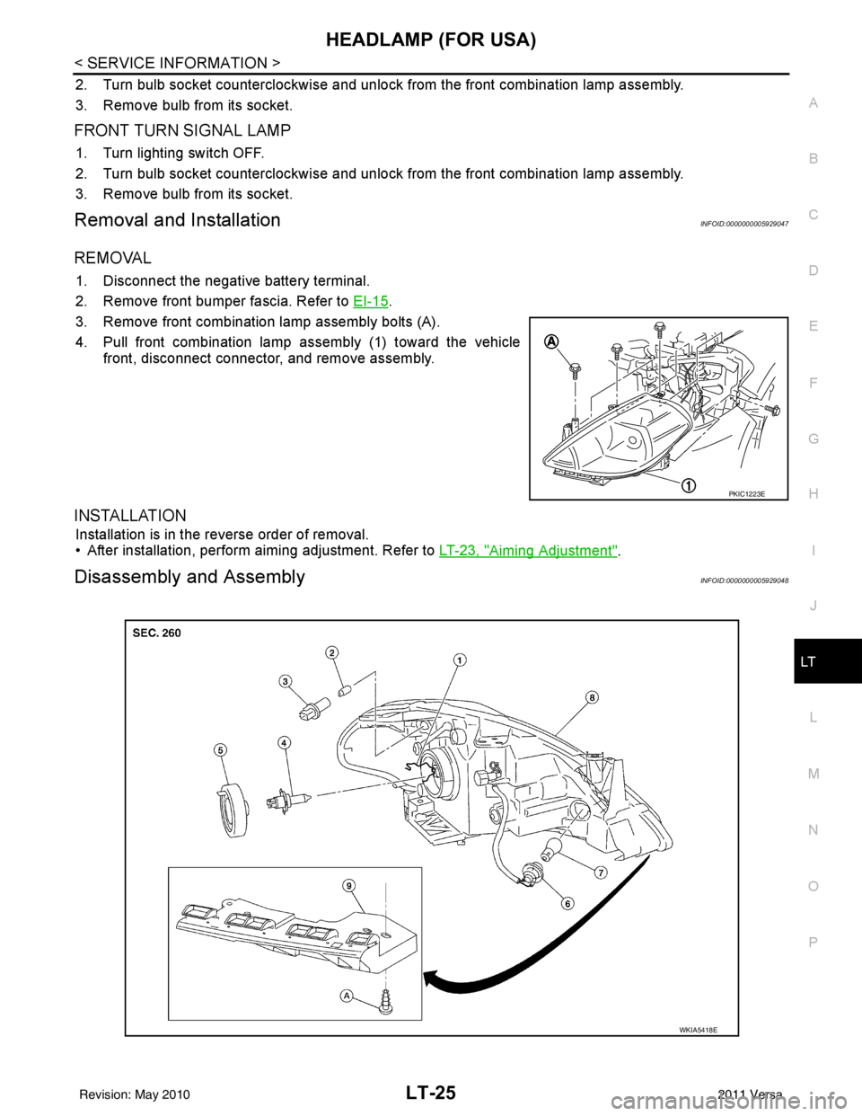
Disassembly and AssemblyINFOID:0000000005929048
PKIC1223E
WKIA5418E
Revision: May 2010 2011 Versa
Page 3058 of 3787

LT-26
< SERVICE INFORMATION >
HEADLAMP (FOR USA)
DISASSEMBLY
1. Remove headlamp bulb back cover.
2. Unlock retaining spring and remove headlamp bulb (High/Low).
3. Turn parking lamp bulb socket counterclockwise and unlock it.
4. Remove parking lamp bulb from its socket.
5. Turn front turn signal lamp bulb socket counterclockwise and unlock it.
6. Remove front turn signal lamp bulb from its socket.
7. Remove the bumper stay.
ASSEMBLY
Assembly is in the reverse order of disassembly.
CAUTION:
• After installing bulb, be sure to install plastic cap secure ly to insure water tight seal.
1. Retaining spring 2. Parking lamp bulb3. Parking lamp bulb socket
4. Halogen headlamp bulb (High/Low) 5. Headlamp bulb back cover 6. Front turn signal lamp bulb socket
7. Front turn signal lamp bulb 8. Front combination lamp assembly 9. Bumper stay
A. Screw
Revision: May 2010 2011 Versa
Page 3071 of 3787
HEADLAMP (FOR CANADA) - DAYTIME LIGHT SYSTEM -
LT-39
< SERVICE INFORMATION >
C
D E
F
G H
I
J
L
M A
B
LT
N
O P
2. Turn bulb socket counterclockwise and unlock from front combination lamp assembly.
3. Remove bulb from its socket.
FRONT TURN SIGNAL LAMP
1. Turn lighting switch OFF.
2. Turn bulb socket counterclockwise and unlock from front combination lamp assembly.
3. Remove bulb from its socket.
Removal and InstallationINFOID:0000000005929063
REMOVAL
1. Disconnect the negative battery terminal.
2. Remove front bumper fascia. Refer to EI-15
.
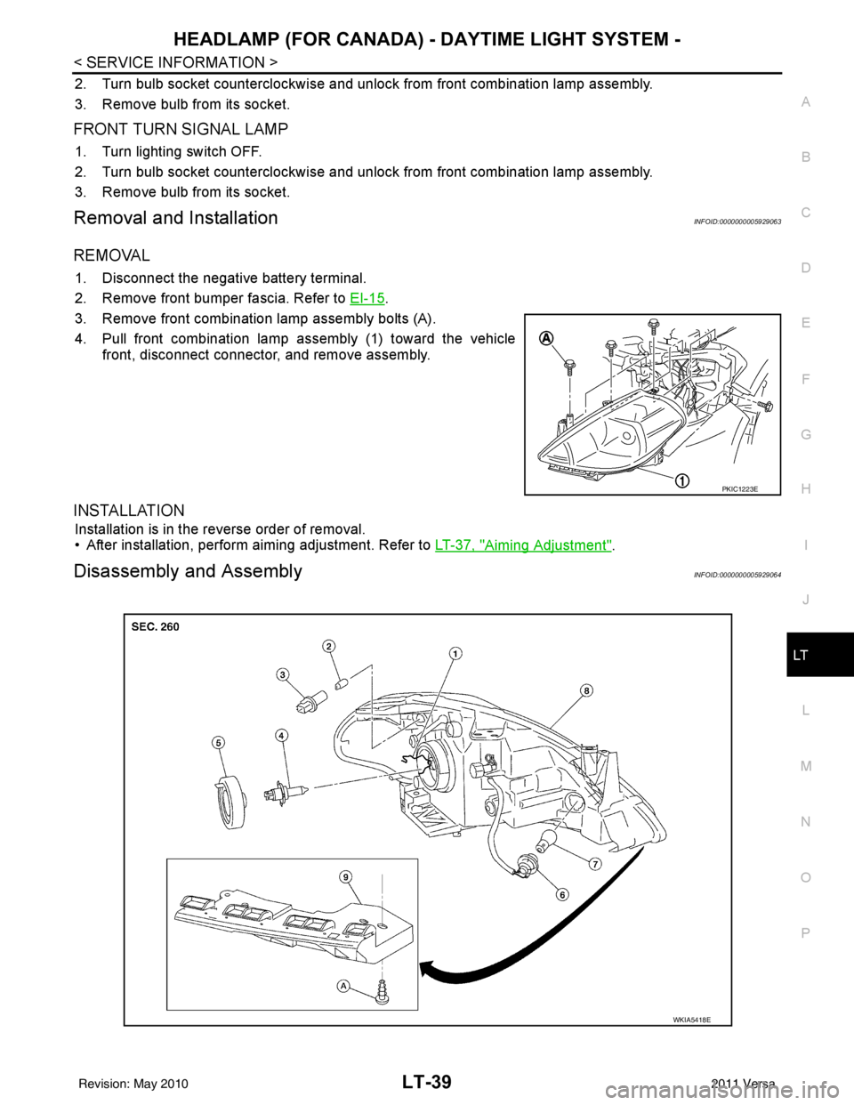
3. Remove front combination lamp assembly bolts (A).
4. Pull front combination lamp assembly (1) toward the vehicle front, disconnect connector, and remove assembly.
INSTALLATION
Installation is in the reverse order of removal.
• After installation, perform aiming adjustment. Refer to LT-37, "
Aiming Adjustment".
Disassembly and AssemblyINFOID:0000000005929064
PKIC1223E
WKIA5418E
Revision: May 2010 2011 Versa
Page 3072 of 3787

LT-40
< SERVICE INFORMATION >
HEADLAMP (FOR CANADA) - DAYTIME LIGHT SYSTEM -
DISASSEMBLY
1. Remove back cover.
2. Unlock retaining spring and remove bulb (High/Low).
3. Turn parking (clearance) lamp bulb socket counterclockwise and unlock it.
4. Remove parking (clearance) lamp bulb from its socket.
5. Turn front turn signal lamp bulb socket counterclockwise and unlock it.
6. Remove front turn signal lamp bulb from its socket.
7. Remove the bumper stay.
ASSEMBLY
Assembly is in the reverse order of disassembly.
CAUTION:
• After installing bulb, be sure to install plastic cap secure ly to insure water tight seal.
1. Retaining spring 2. Parking lamp bulb3. Parking lamp bulb socket
4. Halogen headlamp bulb (High/Low) 5. Headlamp bulb back cover 6. Front turn signal lamp bulb socket
7. Front turn signal lamp bulb 8. Front combination lamp assembly 9. Bumper stay
A. Screw
Revision: May 2010 2011 Versa
Page 3081 of 3787
FRONT FOG LAMPLT-49
< SERVICE INFORMATION >
C
DE
F
G H
I
J
L
M A
B
LT
N
O P
Bulb ReplacementINFOID:0000000005929078
1. Turn lighting switch OFF.
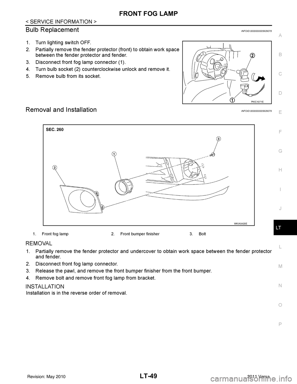
2. Partially remove the fender protec tor (front) to obtain work space
between the fender protector and fender.
3. Disconnect front fog lamp connector (1).
4. Turn bulb socket (2) counterclockwise unlock and remove it.
5. Remove bulb from its socket.
Removal and InstallationINFOID:0000000005929079
REMOVAL
1. Partially remove the fender protector and undercover to obtain work space between the fender protector
and fender.
2. Disconnect front fog lamp connector.
3. Release the pawl, and remove the front bumper finisher from the front bumper.
4. Remove bolt and remove front fog lamp from bracket.
INSTALLATION
Installation is in the reverse order of removal.
PKIC1071E
1. Front fog lamp 2. Front bumper finisher3. Bolt
WKIA5420E
Revision: May 2010 2011 Versa
Page 3116 of 3787
LT-84
< SERVICE INFORMATION >
PARKING, LICENSE PLATE AND TAIL LAMPS
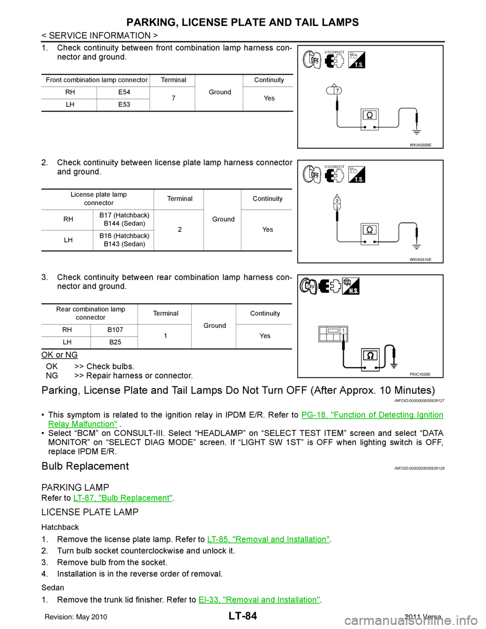
1. Check continuity between front combination lamp harness con-nector and ground.
2. Check continuity between license plate lamp harness connector and ground.
3. Check continuity between rear combination lamp harness con- nector and ground.
OK or NG
OK >> Check bulbs.
NG >> Repair harness or connector.
Parking, License Plate and Tail Lamps Do Not Turn OFF (After Approx. 10 Minutes)
INFOID:0000000005929127
• This symptom is related to the ignition relay in IPDM E/R. Refer to PG-18, "Function of Detecting Ignition
Relay Malfunction" .
• Select “BCM” on CONSULT-III. Select “HEADLAMP” on “SELECT TEST ITEM” screen and select “DATA
MONITOR” on “SELECT DIAG MODE” sc reen. If “LIGHT SW 1ST” is OFF when lighting switch is OFF,
replace IPDM E/R.
Bulb ReplacementINFOID:0000000005929128
PA R K I N G L A M P
Refer to LT-87, "Bulb Replacement".
LICENSE PLATE LAMP
Hatchback
1. Remove the license plate lamp. Refer to LT-85, "Removal and Installation".
2. Turn bulb socket counterclockwise and unlock it.
3. Remove bulb from the socket.
4. Installation is in the reverse order of removal.
Sedan
1. Remove the trunk lid finisher. Refer to EI-33, "Removal and Installation".
Front combination lamp connector Terminal
GroundContinuity
RH E54
7Y es
LH E53
WKIA5509E
License plate lamp
connector Te r m i n a l
GroundContinuity
RH B17 (Hatchback)
B144 (Sedan) 2 Yes
LH B16 (Hatchback)
B143 (Sedan)
WKIA5510E
Rear combination lamp connector Te r m i n a l
GroundContinuity
RH B107
1Y es
LH B25
PKIC1029E
Revision: May 2010 2011 Versa
Page 3119 of 3787
REAR COMBINATION LAMPLT-87
< SERVICE INFORMATION >
C
DE
F
G H
I
J
L
M A
B
LT
N
O P
REAR COMBINATION LAMP
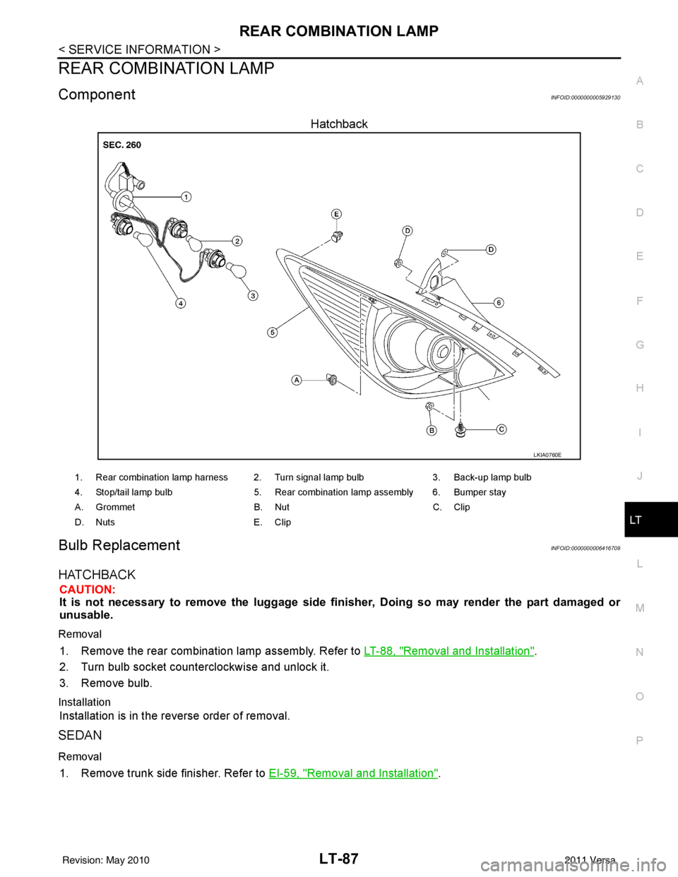
ComponentINFOID:0000000005929130
Hatchback
Bulb ReplacementINFOID:0000000006416709
HATCHBACK
CAUTION:
It is not necessary to remove the lu ggage side finisher, Doing so may render the part damaged or
unusable.
Removal
1. Remove the rear combination lamp assembly. Refer to LT-88, "Removal and Installation".
2. Turn bulb socket counterclockwise and unlock it.
3. Remove bulb.
Installation
Installation is in the reverse order of removal.
SEDAN
Removal
1. Remove trunk side finisher. Refer to EI-59, "Removal and Installation".
LKIA0760E
1. Rear combination lamp harness 2. Turn signal lamp bulb 3. Back-up lamp bulb
4. Stop/tail lamp bulb 5. Rear combination lamp assembly 6. Bumper stay
A. Grommet B. NutC. Clip
D. Nuts E. Clip
Revision: May 2010 2011 Versa