clock NISSAN TIIDA 2011 Service Manual PDF
[x] Cancel search | Manufacturer: NISSAN, Model Year: 2011, Model line: TIIDA, Model: NISSAN TIIDA 2011Pages: 3787, PDF Size: 78.35 MB
Page 3120 of 3787
LT-88
< SERVICE INFORMATION >
REAR COMBINATION LAMP
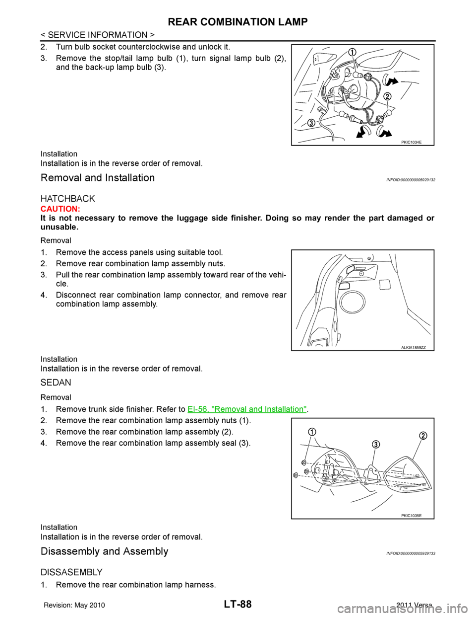
2. Turn bulb socket counterclockwise and unlock it.
3. Remove the stop/tail lamp bulb (1), turn signal lamp bulb (2),and the back-up lamp bulb (3).
Installation
Installation is in the reverse order of removal.
Removal and InstallationINFOID:0000000005929132
HATCHBACK
CAUTION:
It is not necessary to remove the luggage side finisher. Doing so may render the part damaged or
unusable.
Removal
1. Remove the access panels using suitable tool.
2. Remove rear combination lamp assembly nuts.
3. Pull the rear combination lamp assembly toward rear of the vehi-
cle.
4. Disconnect rear combination lamp connector, and remove rear combination lamp assembly.
Installation
Installation is in the reverse order of removal.
SEDAN
Removal
1. Remove trunk side finisher. Refer to EI-56, "Removal and Installation".
2. Remove the rear combination lamp assembly nuts (1).
3. Remove the rear combination lamp assembly (2).
4. Remove the rear combination lamp assembly seal (3).
Installation
Installation is in the reverse order of removal.
Disassembly and AssemblyINFOID:0000000005929133
DISSASEMBLY
1. Remove the rear combination lamp harness.
PKIC1034E
ALKIA1859ZZ
PKIC1035E
Revision: May 2010 2011 Versa
Page 3187 of 3787
MA-16
< SERVICE INFORMATION >
ENGINE MAINTENANCE (HR16DE)
ENGINE MAINTENANCE (HR16DE)
DRIVE BELT
DRIVE BELT : CheckingINFOID:0000000005931137
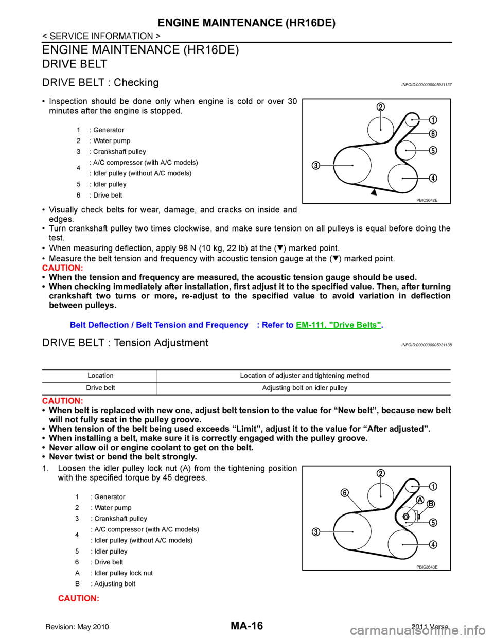
• Inspection should be done only when engine is cold or over 30minutes after the engine is stopped.
• Visually check belts for wear, damage, and cracks on inside and edges.
• Turn crankshaft pulley two times clockwise, and make sure tension on all pulleys is equal before doing the test.
• When measuring deflection, apply 98 N (10 kg, 22 lb) at the ( ) marked point.
• Measure the belt tension and frequency with acous tic tension gauge at the ( ) marked point.
CAUTION:
• When the tension and frequency are measured, the acoustic tension gauge should be used.
• When checking immediately after installation, first ad just it to the specified value. Then, after turning
crankshaft two turns or more, re-adjust to the specified value to avoid variation in deflection
between pulleys.
DRIVE BELT : Tension AdjustmentINFOID:0000000005931138
CAUTION:
• When belt is replaced with new one, adjust belt tension to the value for “New belt”, because new belt will not fully seat in the pulley groove.
• When tension of the belt being used exceeds “Limit”, adjust it to the value for “After adjusted”.
• When installing a belt, make sure it is correctly engaged with the pulley groove.
• Never allow oil or engine coolant to get on the belt.
• Never twist or bend the belt strongly.
1. Loosen the idler pulley lock nut (A) from the tightening position with the specified torque by 45 degrees.
CAUTION:
1 : Generator
2: Water pump
3 : Crankshaft pulley
4: A/C compressor (with A/C models)
: Idler pulley (without A/C models)
5 : Idler pulley
6: Drive belt
Belt Deflection / Belt Tension and Frequency : Refer to EM-111, "Drive Belts".
PBIC3642E
LocationLocation of adjuster and tightening method
Drive belt Adjusting bolt on idler pulley
1 : Generator
2: Water pump
3 : Crankshaft pulley
4 : A/C compressor
(with A/C models)
: Idler pulley (without A/C models)
5 : Idler pulley
6 : Drive belt
A : Idler pulley lock nut
B : Adjusting bolt
PBIC3643E
Revision: May 2010 2011 Versa
Page 3243 of 3787
![NISSAN TIIDA 2011 Service Manual PDF MT-22
< SERVICE INFORMATION >[RS5F91R]
TRANSAXLE ASSEMBLY
DISASSEMBLY
1. Remove drain plug and gasket from clutch housing using a suitable tool and drain gear oil.
2. Remove filler plug and gasket fro NISSAN TIIDA 2011 Service Manual PDF MT-22
< SERVICE INFORMATION >[RS5F91R]
TRANSAXLE ASSEMBLY
DISASSEMBLY
1. Remove drain plug and gasket from clutch housing using a suitable tool and drain gear oil.
2. Remove filler plug and gasket fro](/img/5/57396/w960_57396-3242.png)
MT-22
< SERVICE INFORMATION >[RS5F91R]
TRANSAXLE ASSEMBLY
DISASSEMBLY
1. Remove drain plug and gasket from clutch housing using a suitable tool and drain gear oil.
2. Remove filler plug and gasket from transaxle case.
3. Remove rear housing and O-ring.
CAUTION:
Remove to axial direction of input shaft ( ) because rear
housing oil channel is inserte d to input shaft center hole.
4. Shift control shaft shift lever (1) to the 3rd gear position. NOTE:
• If it is not shifted to the 3rd gear position, transaxle case can-
not be removed from clutch housing.
• The 3rd gear position means that control shaft select lever is
fully rotated clockwise and it is returned approximately 10
degrees.
1. Differential side bearing outer race 2. Differential side bearing 3. Speedometer drive gear
4. Pinion gear 5. Pinion shaft 6. Final drive assembly
Replace parts as a set
JPDIC0602ZZ
SCIA1709J
PCIB1524E
Revision: May 2010 2011 Versa
Page 3253 of 3787
![NISSAN TIIDA 2011 Service Manual PDF MT-32
< SERVICE INFORMATION >[RS5F91R]
TRANSAXLE ASSEMBLY
29. Install 5th-reverse fork rod (1) to clutch housing according to the
following procedures.
CAUTION:
Replace 5th-reverse fork rod and 5th-r NISSAN TIIDA 2011 Service Manual PDF MT-32
< SERVICE INFORMATION >[RS5F91R]
TRANSAXLE ASSEMBLY
29. Install 5th-reverse fork rod (1) to clutch housing according to the
following procedures.
CAUTION:
Replace 5th-reverse fork rod and 5th-r](/img/5/57396/w960_57396-3252.png)
MT-32
< SERVICE INFORMATION >[RS5F91R]
TRANSAXLE ASSEMBLY
29. Install 5th-reverse fork rod (1) to clutch housing according to the
following procedures.
CAUTION:
Replace 5th-reverse fork rod and 5th-reverse shift fork as a
set.
a. Pull gear of reverse gear assembly (2) up.
b. Temporarily install 5th-reverse fork rod to clutch housing.
c. Press gear of reverse gear assembly (1) down and then install 5th-reverse fork rod (2) to clutch housing.
CAUTION:
Set levers of 5th-reverse fork rod so as to align with reverse
gear assembly groove ( ).
30. Install 4th main gear (2) and spacer (1) to mainshaft. CAUTION:
Install spacer so that spacer protrusion faces to transaxle
rear side.
31. Press 3rd-4th shift fork down and then shift 3rd-4th coupling sleeve to 3rd gear side.
32. Shift control shaft shift lever (1) to the 3rd gear position. NOTE:
• If it is not shifted to the 3r d gear position, transaxle case can-
not be installed to clutch housing.
• The 3rd gear position means that control shaft select lever is fully rotated clockwise and it is returned approximately 10
degrees.
33. Apply recommended sealant to transaxle case mounting surface of clutch housing.
•Use Genuine Silicone RT V or an equivalent. GI-42, "
Rec-
ommended Chemical Product and Sealant".
CAUTION:
• Never allow old liquid gasket, moisture, oil, or foreign matte r to remain on mounting surface.
• Check that mounting surface is not damaged.
• Apply a continuous bead of liqu id gasket to the mounting surface.
PCIB1629E
PCIB1552E
PCIB1529E
PCIB1524E
Revision: May 2010 2011 Versa
Page 3254 of 3787
![NISSAN TIIDA 2011 Service Manual PDF TRANSAXLE ASSEMBLYMT-33
< SERVICE INFORMATION > [RS5F91R]
D
E
F
G H
I
J
K L
M A
B
MT
N
O P
34. Install transaxle case to clutch hous ing. If it is difficult to install,
slightly rotate control shaft s NISSAN TIIDA 2011 Service Manual PDF TRANSAXLE ASSEMBLYMT-33
< SERVICE INFORMATION > [RS5F91R]
D
E
F
G H
I
J
K L
M A
B
MT
N
O P
34. Install transaxle case to clutch hous ing. If it is difficult to install,
slightly rotate control shaft s](/img/5/57396/w960_57396-3253.png)
TRANSAXLE ASSEMBLYMT-33
< SERVICE INFORMATION > [RS5F91R]
D
E
F
G H
I
J
K L
M A
B
MT
N
O P
34. Install transaxle case to clutch hous ing. If it is difficult to install,
slightly rotate control shaft shift lever counterclockwise, and then
install.
•1: Selector
• 2: Shift fork
CAUTION:
• Never disrupt liquid gasket bead with transaxle case or
other objects during installation.
• Be careful to align the lever of 5th-reverse fork rod with
reverse gear assembly groove.
35. Rotate input shaft so that bearing and shaft fit each other, and then tighten transaxle bolts ( ) to the specified torque. Refer to
MT-17, "
Exploded View".
36. Apply recommended sealant to the position switch thread and check ball plug thread. tighten them to tran- saxle case to specified torque.
•Use Genuine Silicon RTV or an equivalent. Refer to GI-42, "
Recommended Chemical Product and
Sealant".
CAUTION:
Never allow old liquid gasket, moisture, oil, or foreign matter to remain on thread.
37. Apply gear oil to mainshaft spline.
38. Install 5th main gear (1) to mainshaft using a suitable bolt (A) [M10 x 1.0] and a suitable nut (B).
39. Install adapter plate (1), bushing (2), and 5th input gear (3) to input shaft.
CAUTION:
Be careful with the orientation of adapter plate.
• : Transaxle case side
40. Install 5th-reverse synchronizer hub, 5th-reverse c oupling sleeve, and 5th-reverse shift fork according to
the following procedures.
a. Apply gear oil to 5th-reverse baulk ring.
PCIB1553E
JPDIC0610ZZ
PCIB1554E
PCIB1555E
Revision: May 2010 2011 Versa
Page 3325 of 3787
PRECAUTIONSMTC-9
< SERVICE INFORMATION >
C
DE
F
G H
I
K L
M A
B
MTC
N
O P
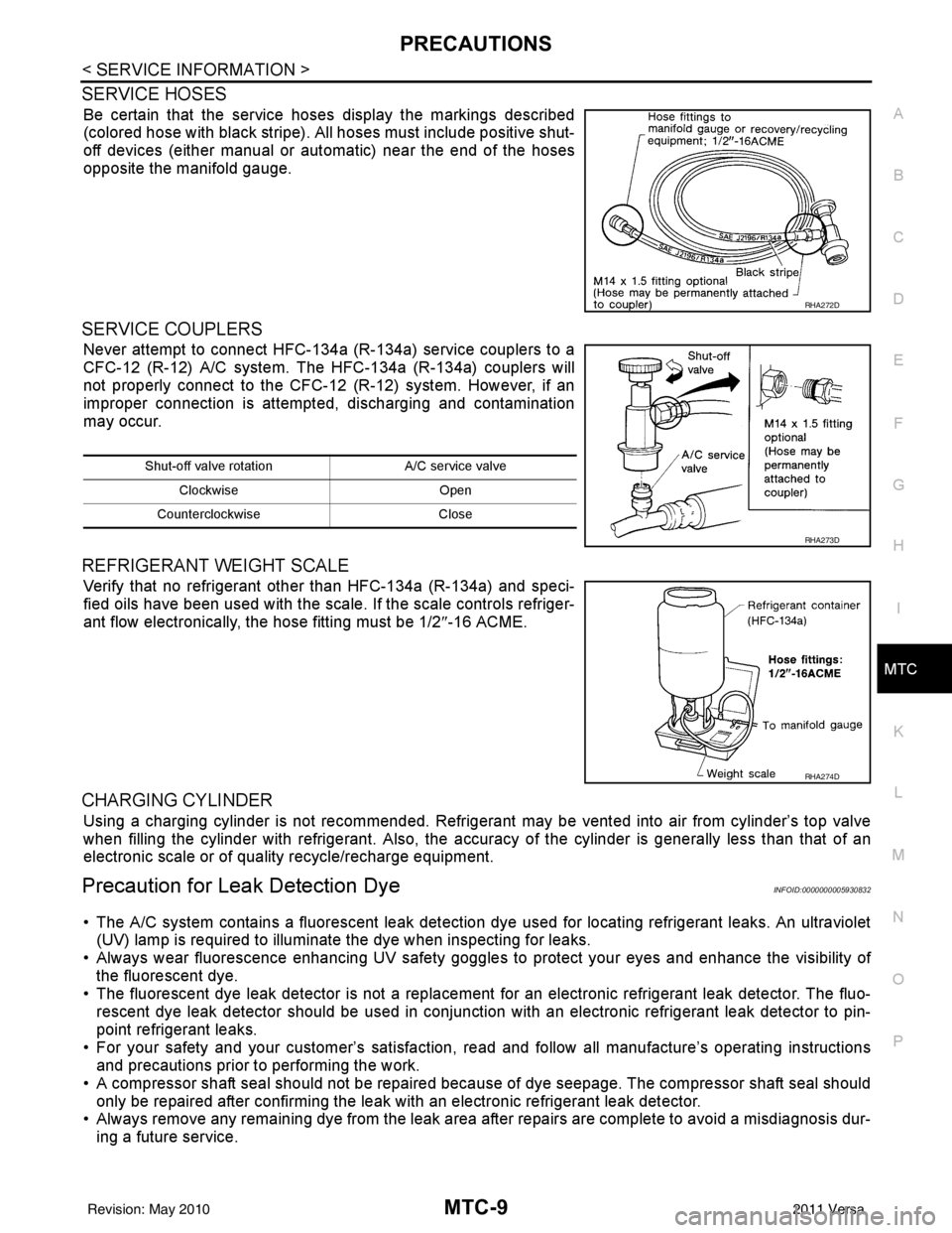
SERVICE HOSES
Be certain that the service hoses display the markings described
(colored hose with black stripe). All hoses must include positive shut-
off devices (either manual or aut omatic) near the end of the hoses
opposite the manifold gauge.
SERVICE COUPLERS
Never attempt to connect HFC-134a (R-134a) service couplers to a
CFC-12 (R-12) A/C system. The HFC-134a (R-134a) couplers will
not properly connect to the CFC-12 (R-12) system. However, if an
improper connection is attempted, discharging and contamination
may occur.
REFRIGERANT WEIGHT SCALE
Verify that no refrigerant other than HFC-134a (R-134a) and speci-
fied oils have been used with the scale. If the scale controls refriger-
ant flow electronically, the hose fitting must be 1/2 ″-16 ACME.
CHARGING CYLINDER
Using a charging cylinder is not re commended. Refrigerant may be vented into air from cylinder’s top valve
when filling the cylinder with refrigerant. Also, the accura cy of the cylinder is generally less than that of an
electronic scale or of quality recycle/recharge equipment.
Precaution for Leak Detection DyeINFOID:0000000005930832
• The A/C system contains a fluorescent leak detection dy e used for locating refrigerant leaks. An ultraviolet
(UV) lamp is required to illuminate the dye when inspecting for leaks.
• Always wear fluorescence enhancing UV safety goggles to protect your eyes and enhance the visibility of
the fluorescent dye.
• The fluorescent dye leak detector is not a replacement for an electronic refrigerant leak detector. The fluo-
rescent dye leak detector should be used in conjunction with an electronic refrigerant leak detector to pin-
point refrigerant leaks.
• For your safety and your customer’s satisfaction, read and follow all manufacture’s operating instructions
and precautions prior to performing the work.
• A compressor shaft seal should not be repaired because of dye seepage. The compressor shaft seal should
only be repaired after confirming the leak with an electronic refrigerant leak detector.
• Always remove any remaining dye from the leak area after repairs are complete to avoid a misdiagnosis dur-
ing a future service.
RHA272D
Shut-off valve rotati on A/C service valve
Clockwise Open
Counterclockwise Close
RHA273D
RHA274D
Revision: May 2010 2011 Versa
Page 3348 of 3787
MTC-32
< SERVICE INFORMATION >
TROUBLE DIAGNOSIS
1. Turn blower control dial clockwise to "1" position. Blower should operate on low speed.
2. Turn blower control dial clockwise to "2" position, and continue checking blower speed until all speeds are
checked.
3. Leave blower on Maximum speed.
If NG, go to trouble diagnosis procedure for MTC-34, "
Front Blower Motor Circuit".
If OK, continue the check.
CHECKING DISCHARGE AIR
1. Turn mode door control dial to each position.
2. Confirm that discharge air comes out according to the air distribution table. Refer to MTC-20, "
Discharge
Air Flow".
If NG, go to trouble diagnosis procedure for MTC-32, "
Mode Door".
If OK, continue the check.
CHECKING RECIRCULATION
1. Set intake door lever to REC position.
2. Operate intake door lever to FRE position.
3. Listen for intake door position change (you should hear blower sound change slightly).
If NG, go to trouble diagnosis procedure for MTC-34, "
Intake Door".
If OK, continue the check.
CHECKING TEMPERATURE DECREASE
1. Turn temperature control dial counterclockwise to full cold position.
2. Check for cold air at discharge air outlets.
If NG, go to trouble diagnosis procedure for MTC-46, "
Insufficient Cooling".
If OK, continue the check.
CHECKING TEMPERATURE INCREASE
1. Turn temperature control dial clockwise to full hot position.
2. Check for hot air at discharge air outlets.
If NG, go to trouble diagnosis procedure for MTC-53, "
Insufficient Heating".
If OK, continue the check.
CHECKING A/C SWITCH (IF EQUIPPED)
1. Turn fan control dial to the desired (1 to 4 speed) position.
2. Press A/C switch.
3. A/C switch indicator will turn ON.
• Confirm that the compressor clutch engages (sound or visual inspection).
If NG, go to trouble diagnosis procedure for MTC-38, "
Magnet Clutch Circuit (If Equipped)".
If OK, continue the check.
CHECKING DEFROST A/C SWITCH (IF EQUIPPED)
1. Turn fan control dial to the desired (1 to 4 speed) position.
2. Turn mode dial to ( ) DEF.
3. Confirm that the compressor clutch engages (sound or visual inspection) and the A/C switch indicator illu- minates.
If NG, go to trouble diagnosis procedure for MTC-38, "
Magnet Clutch Circuit (If Equipped)".
If all operational checks are OK (symptom cannot be duplicated), go to MTC-23, "
How to Perform Trouble
Diagnosis for Quick and Accurate Repair" and perform tests as outlined. If symptom appears, refer to MTC-23,
"How to Perform Trouble Diagnosis for Quick and Accurate Repair" and perform applicable trouble diagnosis
procedures.
Mode DoorINFOID:0000000005930849
SYMPTOM: Air outlet does not change.
INSPECTION FLOW
Revision: May 2010 2011 Versa
Page 3349 of 3787
TROUBLE DIAGNOSISMTC-33
< SERVICE INFORMATION >
C
DE
F
G H
I
K L
M A
B
MTC
N
O P
1.CONFIRM SYMPTOM BY PERFORMING O PERATIONAL CHECK - DISCHARGE AIR
1. Rotate the mode door control dial to each position.
2. Confirm that discharge air comes out accord ing to the air distribution table. Refer to MTC-20, "
Discharge
Air Flow".
NOTE:
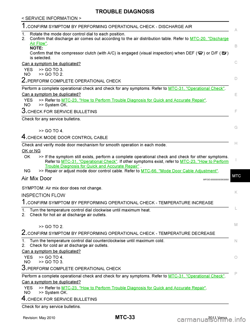
Confirm that the compressor clutch (with A/C) is engaged (visual inspection) when DEF ( ) or D/F ( )
is selected.
Can a symptom be duplicated?
YES >> GO TO 3.
NO >> GO TO 2.
2.PERFORM COMPLETE OPERATIONAL CHECK
Perform a complete operational check and check for any symptoms. Refer to MTC-31, "
Operational Check".
Can a symptom be duplicated?
YES >> Refer to MTC-23, "How to Perform Trouble Diagnosis for Quick and Accurate Repair".
NO >> System OK.
3.CHECK FOR SERVICE BULLETINS
Check for any service bulletins.
>> GO TO 4.
4.CHECK MODE DOOR CONTROL CABLE
Check and verify mode door mechanism for smooth operation in each mode.
OK or NG
OK >> If the symptom still exists, perform a comple te operational check and check for other symptoms.
Refer to MTC-31, "
Operational Check". If other symptoms exist, refer to MTC-23, "How to Perform
Trouble Diagnosis for Quick and Accurate Repair" .
NG >> Repair or adjust mode door control cable. Refer to MTC-66, "
Mode Door Cable Adjustment".
Air Mix DoorINFOID:0000000005930850
SYMPTOM: Air mix door does not change.
INSPECTION FLOW
1.CONFIRM SYMPTOM BY PERFORMING OPERATIONAL CHECK - TEMPERATURE INCREASE
1. Turn the temperature control dial clockwise until maximum heat.
2. Check for hot air at discharge air outlets.
>> GO TO 2.
2.CONFIRM SYMPTOM BY PERFORMING OPERAT IONAL CHECK - TEMPERATURE DECREASE
1. Turn the temperature control dial counterclockwise until maximum cold.
2. Check for cold air at discharge air outlets.
Can a symptom be duplicated?
YES >> GO TO 4.
NO >> GO TO 3.
3.PERFORM COMPLETE OPERATIONAL CHECK
Perform a complete operational check and check for any symptoms. Refer to MTC-31, "
Operational Check".
Can a symptom be duplicated?
YES >> Refer to MTC-23, "How to Perform Trouble Diagnosis for Quick and Accurate Repair".
NO >> System OK.
4.CHECK FOR SERVICE BULLETINS
Check for any service bulletins.
Revision: May 2010 2011 Versa
Page 3358 of 3787
MTC-42
< SERVICE INFORMATION >
TROUBLE DIAGNOSIS
1. Turn ignition switch OFF.
2. Disconnect front air control connector and BCM connector.
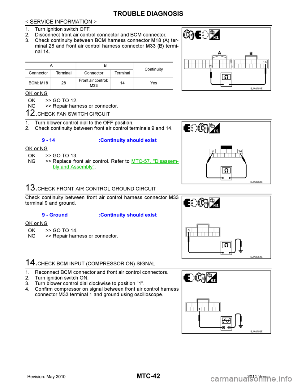
3. Check continuity between BCM harness connector M18 (A) ter-minal 28 and front air control harness connector M33 (B) termi-
nal 14.
OK or NG
OK >> GO TO 12.
NG >> Repair harness or connector.
12.CHECK FAN SWITCH CIRCUIT
1. Turn blower control dial to the OFF position.
2. Check continuity between front air control terminals 9 and 14.
OK or NG
OK >> GO TO 13.
NG >> Replace front air control. Refer to MTC-57, "
Disassem-
bly and Assembly".
13.CHECK FRONT AIR CONTROL GROUND CIRCUIT
Check continuity between front air control harness connector M33
terminal 9 and ground.
OK or NG
OK >> GO TO 14.
NG >> Repair harness or connector.
14.CHECK BCM INPUT (COMPRESSOR ON) SIGNAL
1. Reconnect BCM connector and front air control connectors.
2. Turn ignition switch ON.
3. Turn blower control dial clockwise to position "1".
4. Confirm compressor on signal between front air control harness connector M33 terminal 1 and ground using oscilloscope.
AB Continuity
Connector Terminal Connector Terminal
BCM: M18 28 Front air control:
M33 14
Yes
SJIA0751E
9 - 14 :Continuity should exist
SJIA0753E
9 - Ground :Continuity should exist
SJIA0754E
SJIA0755E
Revision: May 2010 2011 Versa
Page 3362 of 3787
MTC-46
< SERVICE INFORMATION >
TROUBLE DIAGNOSIS
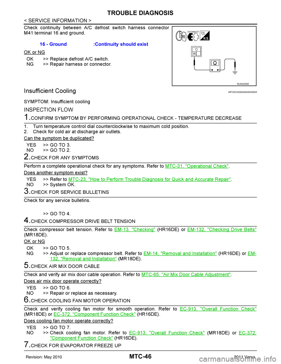
Check continuity between A/C defrost switch harness connector
M41 terminal 16 and ground.
OK or NG
OK >> Replace defrost A/C switch.
NG >> Repair harness or connector.
Insufficient CoolingINFOID:0000000005930854
SYMPTOM: Insufficient cooling
INSPECTION FLOW
1.CONFIRM SYMPTOM BY PERFORMING OPERATIONAL CHECK - TEMPERATURE DECREASE
1. Turn temperature control dial counterclockwise to maximum cold position.
2. Check for cold air at discharge air outlets.
Can the symptom be duplicated?
YES >> GO TO 3.
NO >> GO TO 2.
2.CHECK FOR ANY SYMPTOMS
Perform a complete operational check for any symptoms. Refer to MTC-31, "
Operational Check".
Does another symptom exist?
YES >> Refer to MTC-23, "How to Perform Trouble Diagnosis for Quick and Accurate Repair".
NO >> System OK.
3.CHECK FOR SERVICE BULLETINS
Check for any service bulletins.
>> GO TO 4.
4.CHECK COMPRESSOR DRIVE BELT TENSION
Check compressor belt tension. Refer to EM-13, "
Checking" (HR16DE) or EM-132, "Checking Drive Belts"
(MR18DE).
OK or NG
OK >> GO TO 5.
NG >> Adjust or replace compressor belt. Refer to EM-14, "
Removal and Installation" (HR16DE) or EM-
132, "Removal and Installation" (MR18DE).
5.CHECK AIR MIX DOOR CABLE
Check and verify air mix door cable operation. Refer to MTC-65, "
Air Mix Door Cable Adjustment".
Does air mix door operate correctly?
YES >> GO TO 6.
NO >> Repair or replace as necessary.
6.CHECK COOLING FAN MOTOR OPERATION
Check and verify cooling fan motor for smooth operation. Refer to EC-913, "
Overall Function Check"
(MR18DE) or EC-372, "Component Function Check" (HR16DE).
Does cooling fan motor operate correctly?
YES >> GO TO 7.
NO >> Check cooling fan motor. Refer to EC-913, "
Overall Function Check" (MR18DE) or EC-372,
"Component Function Check" (HR16DE).
7.CHECK FOR EVAPORATOR FREEZE UP16 - Ground :Continuity should exist
WJIA2255E
Revision: May 2010
2011 Versa