front axle NISSAN TIIDA 2011 Service Manual PDF
[x] Cancel search | Manufacturer: NISSAN, Model Year: 2011, Model line: TIIDA, Model: NISSAN TIIDA 2011Pages: 3787, PDF Size: 78.35 MB
Page 3295 of 3787

MT-74
< SERVICE INFORMATION >[RS6F94R]
TRANSAXLE ASSEMBLY
4. Install two way connector (1) to clutch housing.
5. Install bushings (1) so that they becomes even to clutch housing
edge surface, using a suitable tool (A).
6. Install oil channel to clutch housing. CAUTION:
Never reuse oil channel.
7. Install mainshaft front bearing outer race to clutch housing, using Tool (A).
CAUTION:
Replace mainshaft front bearing outer race and mainshaft
front bearing inner race as a set.
8. Install input shaft oil seal (1) to clutch housing, using Tool (A).
9. Install snap ring (1) and oil channel (2) to transaxle case. CAUTION:
• Select and install snap ring that has the same thickness
as previous one.
• Replace transaxle assembly when replacing transaxle case.
10. Install mainshaft rear bearing adjusting shim to transaxle case. CAUTION:
Select mainshaft rear bearin g adjusting shim according to
the following procedures when replacing mainshaft adjust-
ing shim, 6th main gear, 5th main gear, or 4th main gear.
• Replace mainshaft adjusting shim.
PCIB1720E
JPDIC0108ZZ
Tool number : KV38100200 ( — )
PCIB1724E
Tool number : ST33220000 ( — )
PCIB1721E
PCIB1729E
Revision: May 2010 2011 Versa
Page 3308 of 3787

MAINSHAFT AND GEARSMT-87
< SERVICE INFORMATION > [RS6F94R]
D
E
F
G H
I
J
K L
M A
B
MT
N
O P
Check contact surface of baulk ring cam and insert key for exces-
sive wear, uneven wear, bend, and damage. Replace if necessary.
Bearing
Check bearing for damage and unsmooth rotation. Replace if neces-
sary.
CAUTION:
• Replace mainshaft front bearing outer race and mainshaft front bearing inner race as a set.
• Replace mainshaft rear bearin g inner race and mainshaft rear
bearing outer race as a set.
ASSEMBLY
CAUTION:
• Select mainshaft rear bearing adjusting shim acco rding to the following procedures when replacing
mainshaft adjusting shim, 6th main gear , 5th main gear, or 4th main gear.
- Replace mainshaft adjusting shim.
• If new mainshaft adjusting shim is thinner than previous one, offset the thickness difference by
selecting thicker mainshaft r ear bearing adjusting shim.
• If new mainshaft adjusting shim is thicker th an previous one, offset the thickness difference by
selecting thinner mainshaft rear bearing adjusting shim.
- Replace 6th main gear, 5th main gear, or 4th main gear.
• Measure the thickness of the main gear used before and the new main gear
• Increase the thickness of the mainsh aft rear bearing adjusting shim, if the difference is smaller than
0.025 mm (0.0010 in).
• Replace transaxle assembly when replacing mainshaft.
1. Install mainshaft front bearing inner race (1) using the Tool (A).
CAUTION:
Replace mainshaft front bearing outer race and mainshaft
front bearing inner race as a set.
2. Apply gear oil to 1st inner baulk ring, 1st synchronizer cone, 1st outer baulk ring, 2nd inner baulk ring, 2nd synchronizer cone,
and 2nd outer baulk ring.
CAUTION:
• Replace 1st inner baulk ring, 1st synchronizer cone, and
1st outer baulk ring as a set.
• Replace 2nd inner baulk ring, 2nd synchronize r cone, and 2nd outer baulk ring as a set.
3. Install insert keys and 1st-2nd coupling sleeve to 1st-2nd synchronizer hub. CAUTION:
Replace 1st-2nd synchroni zer hub and 1st-2nd coupling sleeve as a set.
SCIA0608J
SPD715
Tool number A: ST36720030 ( — )
PCIB1733E
Revision: May 2010 2011 Versa
Page 3500 of 3787
PS-6
< SERVICE INFORMATION >
STEERING WHEEL
STEERING WHEEL
On-Vehicle Inspection and ServiceINFOID:0000000006416714
CHECKING CONDITION OF INSTALLATION
• Check installation conditions of steering gear assembly, front suspension assembly, axle and steering col-
umn assembly.
• Check if movement exists when steering wheel is mo ved up and down, to the left and right and to the axial
direction.
• Check steering gear assembly bolts and nuts for looseness. Refer to PS-15, "
Removal and Installation".
CHECKING STEERING WHEEL PLAY
• Turn steering wheel so that front wheels come to the straight-ahead position. Start engine and lightly turn
steering wheel to the left and right until front wheels start to move. Measure steering wheel movement on the
outer circumference.
• When the measurement value is outside the standard val ue, check backlash for each joint of steering col-
umn assembly and installation condition of steering gear assembly.
CHECKING NEUTRAL POSITION STEERING WHEEL
• Make sure that steering gear assembly, steering column assembly and steering wheel are installed in the correct position.
• Perform neutral position inspection after wheel alignment. Refer to PS-2, "
Precaution for Supplemental
Restraint System (SRS) "AIR BAG" and "SEAT BELT PRE-TENSIONER"".
• Set vehicle to the straight-ahead position and c onfirm steering wheel is in the neutral position.
• Loosen outer socket lock nut and turn inner socket to left and right equally to make fine adjustments if steer-
ing wheel is not in the neutral position.
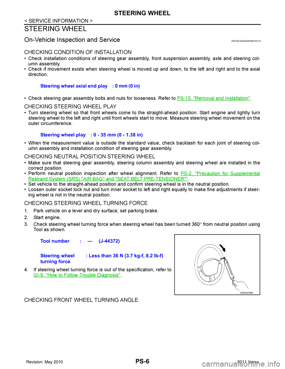
CHECKING STEERING WHEEL TURNING FORCE
1. Park vehicle on a level and dry surface, set parking brake.
2. Start engine.
3. Check steering wheel turning force when steering wheel has been turned 360 ° from neutral position using
Tool as shown.
4. If steering wheel turning force is out of the specification, refer to GI-9, "
How to Follow Trouble Diagnosis".
CHECKING FRONT WHEEL TURNING ANGLE
Steering wheel axial end play : 0 mm (0 in)
Steering wheel play : 0 - 35 mm (0 - 1.38 in)
Tool number : — (J-44372)
Steering wheel
turning force : Less than 36 N (3.7 kg-f, 8.2 lb-f)
WGIA0180E
Revision: May 2010
2011 Versa
Page 3723 of 3787
NOISE, VIBRATION AND HARSHNESS (NVH) TROUBLESHOOTINGWT-5
< SERVICE INFORMATION >
C
DF
G H
I
J
K L
M A
B
WT
N
O P
NOISE, VIBRATION AND HARSHN ESS (NVH) TROUBLESHOOTING
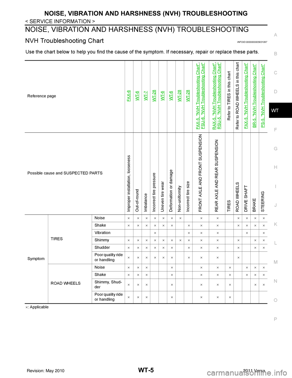
NVH Troubleshooting ChartINFOID:0000000005931097
Use the chart below to help you find t he cause of the symptom. If necessary, repair or replace these parts.
×: Applicable
Reference page
FAX-6WT-6
WT-7
WT-28WT-6
WT-6
WT-28WT-28
FAX-5, "
NVH Troubleshooting Chart
",
FSU-6, "
NVH Troubleshooting Chart
"
RAX-5, "
NVH Troubleshooting Chart
",
RSU-5, "
NVH Troubleshooting Chart
"
Refer to TIRES in this chart
Refer to ROAD WHEELS in this chart
FAX-5, "
NVH Troubleshooting Chart
"
BR-5, "
NVH Troubleshooting Chart
"
PS-5, "
NVH Troubleshooting Chart
"
Possible cause and SUSPECTED PARTS
Improper installation, looseness
Out-of-round
Imbalance
Incorrect tire pressure
Uneven tire wear
Deformation or damage
Non-uniformity
Incorrect tire size
FRONT AXLE AND FRONT SUSPENSION
REAR AXLE AND REAR SUSPENSION
TIRES
ROAD WHEELS
DRIVE SHAFT
BRAKE
STEERING
Symptom TIRES Noise
× ×××××× × × ××××
Shake × ××××× × × × ××××
Vibration ××××××
Shimmy × ××××××× × × × ××
Shudder × ××××× × × × × ××
Poor quality ride
or handling × ××××× × × × ×
ROAD WHEELS Noise
× ×× × × × × ×××
Shake × ×× × × × × ×××
Shimmy, Shud-
der ××× × × × × ××
Poor quality ride
or handling ××× × × × ×
Revision: May 2010
2011 Versa