front axle NISSAN TIIDA 2011 Service Workshop Manual
[x] Cancel search | Manufacturer: NISSAN, Model Year: 2011, Model line: TIIDA, Model: NISSAN TIIDA 2011Pages: 3787, PDF Size: 78.35 MB
Page 3182 of 3787
PERIODIC MAINTENANCEMA-11
< SERVICE INFORMATION >
C
DE
F
G H
I
J
K
M A
B
MA
N
O P
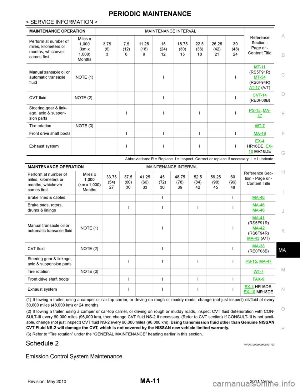
Abbreviations: R = Replace. I = Inspect. Corr ect or replace if necessary. L = Lubricate.
(1) If towing a trailer, using a camper or car-top carrier, or driving on rough or muddy roads, change (not just inspect) oil/f luid at every
30,000 miles (48,000 km) or 24 months.
(2) If towing a trailer, using a camper or car-top carrier, or driving on rough or muddy roads, inspect CVT fluid deterioration with CON-
SULT-III every 60,000 miles (96,000 km), then change CVT fluid NS -2 if necessary. (Refer to CVT section) If CONSULT-III is not avail-
able, change (not just inspect) CVT fluid NS-2 every 60,000 miles (96,000 km). Using transmission fluid other than Genuine NISSAN
CVT Fluid NS-2 will damage the CVT, which is not covered by the NISSAN new vehicle limited warranty.
(3) Refer to “Tire rotation” under the “GENERAL MAINTENANCE” heading earlier in this section.
Schedule 2INFOID:0000000005931133
Emission Control System Maintenance
Manual transaxle oil or
automatic transaxle
fluidNOTE (1)
IIMT-11
(RS5F91R) MT-54
(RS6F94R)
AT- 1 7
(A/T)
CVT fluid NOTE (2) IICVT-14
(RE0F08B)
Steering gear & link-
age, axle & suspen-
sion parts IIII
PS-15
, MA-
47
Tire rotation
NOTE (3) WT-7
Front drive shaft bootsIIIIMA-48
Exhaust system IIIIEX-4
HR16DE, EX-
10 MR18DE
MAINTENANCE OPERATION
MAINTENANCE INTERVAL
Reference Section -
Page or -
Content Title
Perform at number of
miles, kilometers or
months, whichever
comes first. Miles x
1,000
(km x
1,000)
Months 3.75
(6)3 7.5
(12) 6 11 . 2 5
(18) 9 15
(24) 12 18.75
(30)15 22.5
(36) 18 26.25
(42)21 30
(48) 24
MAINTENANCE OPERATION MAINTENANCE INTERVAL
Reference Sec-tion - Page or - Content Title
Perform at number of
miles, kilometers or
months, whichever
comes first. Miles x
1,000
(km x 1,000)
Months 33.75
(54)27 37.5
(60) 30 41.25
(66)33 45
(72) 36 48.75
(78)39 52.5
(84) 42 56.25
(90)45 60
(96) 48
Brake lines & cables IIMA-46
Brake pads, rotors,
drums & linings II I I
MA-46
MA-46
Manual transaxle oil or
automatic transaxle fluidNOTE (1)
IIMA-41
(RS5F91R)
MA-42
(RS6F94R)
MA-43
(A/T)
CVT fluid NOTE (2) IIMA-38
(RE0F08B)
Steering gear & linkage,
axle & suspension parts II I I
PS-15
, MA-47
Tire rotationNOTE (3) WT-7
Front drive shaft bootsII IIFAX-9
Exhaust system II IIEX-4 HR16DE,
EX-10
MR18DE
Revision: May 2010 2011 Versa
Page 3192 of 3787
ENGINE MAINTENANCE (HR16DE)MA-21
< SERVICE INFORMATION >
C
DE
F
G H
I
J
K
M A
B
MA
N
O P
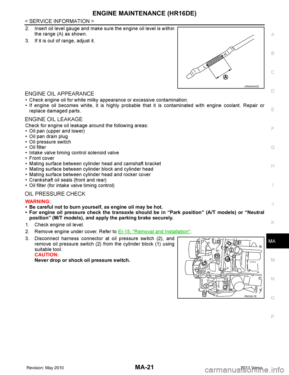
2. Insert oil level gauge and make sure the engine oil level is within the range (A) as shown.
3. If it is out of range, adjust it.
ENGINE OIL APPEARANCE
• Check engine oil for white milky appearance or excessive contamination.
• If engine oil becomes white, it is highly probable t hat it is contaminated with engine coolant. Repair or
replace damaged parts.
ENGINE OIL LEAKAGE
Check for engine oil leakage around the following areas:
• Oil pan (upper and lower)
• Oil pan drain plug
• Oil pressure switch
• Oil filter
• Intake valve timing control solenoid valve
• Front cover
• Mating surface between cylinder head and camshaft bracket
• Mating surface between cylinder block and cylinder head
• Mating surface between cylinder head and rocker cover
• Crankshaft oil seals (front and rear)
• Oil filter (for intake valve timing control)
OIL PRESSURE CHECK
WARNING:
• Be careful not to burn yoursel f, as engine oil may be hot.
• For engine oil pressure check the transaxle should be in “Park position” (A/T models) or “Neutral
position” (M/T models), and apply the parking brake securely.
1. Check engine oil level.
2. Remove engine under cover. Refer to EI-15, "
Removal and Installation".
3. Disconnect harness connector at oil pressure switch (2), and remove oil pressure switch (2) from the cylinder block (1) using
suitable tool.
CAUTION:
Never drop or shock oil pressure switch.
JPBIA0554ZZ
PBIC3817E
Revision: May 2010 2011 Versa
Page 3202 of 3787
ENGINE MAINTENANCE (MR18DE)MA-31
< SERVICE INFORMATION >
C
DE
F
G H
I
J
K
M A
B
MA
N
O P
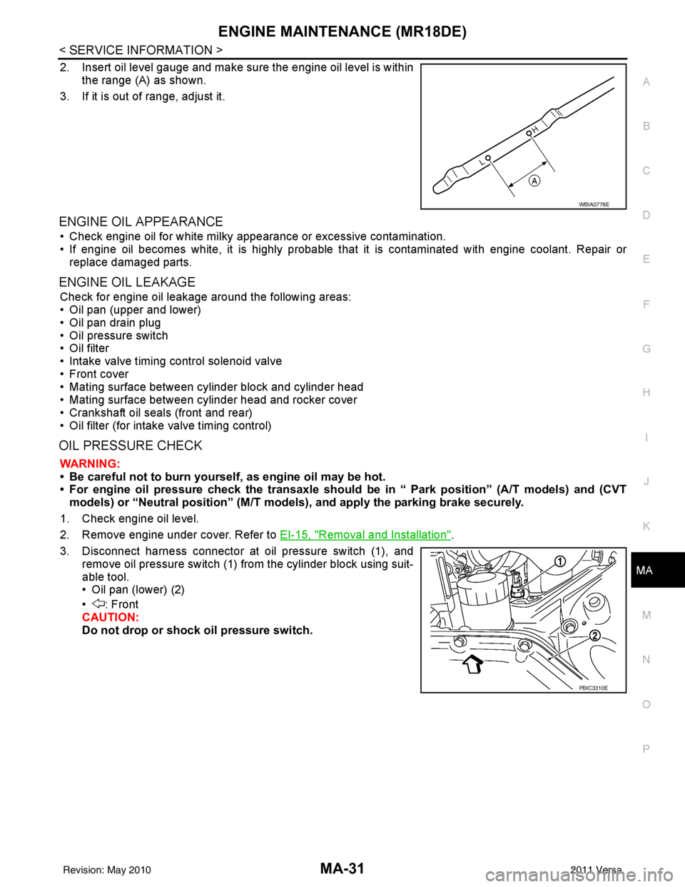
2. Insert oil level gauge and make sure the engine oil level is within the range (A) as shown.
3. If it is out of range, adjust it.
ENGINE OIL APPEARANCE
• Check engine oil for white milky appearance or excessive contamination.
• If engine oil becomes white, it is highly probable t hat it is contaminated with engine coolant. Repair or
replace damaged parts.
ENGINE OIL LEAKAGE
Check for engine oil leakage around the following areas:
• Oil pan (upper and lower)
• Oil pan drain plug
• Oil pressure switch
• Oil filter
• Intake valve timing control solenoid valve
• Front cover
• Mating surface between cylinder block and cylinder head
• Mating surface between cylinder head and rocker cover
• Crankshaft oil seals (front and rear)
• Oil filter (for intake valve timing control)
OIL PRESSURE CHECK
WARNING:
• Be careful not to burn yoursel f, as engine oil may be hot.
• For engine oil pressure check the transaxle should be in “ Park position” (A/T models) and (CVT
models) or “Neutral position” (M/T mode ls), and apply the parking brake securely.
1. Check engine oil level.
2. Remove engine under cover. Refer to EI-15, "
Removal and Installation".
3. Disconnect harness connector at oil pressure switch (1), and remove oil pressure switch (1) from the cylinder block using suit-
able tool.
• Oil pan (lower) (2)
• : Front
CAUTION:
Do not drop or shock oil pressure switch.
WBIA0776E
PBIC3310E
Revision: May 2010 2011 Versa
Page 3210 of 3787

CHASSIS AND BODY MAINTENANCEMA-39
< SERVICE INFORMATION >
C
DE
F
G H
I
J
K
M A
B
MA
N
O P
• : Vehicle front
• Radiator (2)
• CVT fluid cooler hose [inlet side (3)]
• Transaxle assembly (4)
2. Drain CVT fluid from CVT fluid cooler hose [outlet side (1)] and refill with new specified NISSAN CVT fluid in the CVT fluid
charging pipe with the engine running at idle speed.
CAUTION:
Only use the specifi ed NISSAN CVT fluid.
3. Refill until new CVT fluid comes out from CVT fluid cooler hose [outlet side (1)]. NOTE:
About 30 to 50% extra fluid will be required for this procedure.
4. Check fluid level and condition. Refer to MA-37, "
CVT FLUID : Checking CVT Fluid".
CAUTION:
Delete CVT fluid deterioration date with CONSULT-III after changing CVT fluid. Refer to CVT-48,
"CONSULT-III Function (TRANSMISSION)".
CLUTCH FLUID
CLUTCH FLUID : Air Bleeding ProcedureINFOID:0000000005931169
CAUTION:
Do not spill clutch fluid onto painted surfaces. If it spills, wipe up immediately and wash the affected
area with water.
NOTE:
• Do not use a vacuum assist or any other type of power bleeder on this system. Use of a vacuum assist or power bleeder will not purge all the air from the system.
• Carefully monitor fluid level in reservoir tank during bleeding operation.
1. Fill master cylinder reservoir tank with new clutch fluid.
2. Connect a transparent vinyl tube and container to the bleeding connector (1) on the CSC.
3. Depress and release the clutch pedal slowly and fully 15 times at an interval of two to three seconds and release the clutch
pedal.
4. Push in the lock pin (1) of the bleeding connector (2), and maintain the position. • RS5F91R transaxle models
CAUTION:
Hold the lock pin in to preven t the bleeding connector from
separating when fluid pressure is applied.
Fluid capacity and grade: Refer to
MA-14, "
Fluids
and Lubricants".SCIA6088E
PCIB1494E
PCIB1495E
Revision: May 2010 2011 Versa
Page 3213 of 3787
MA-42
< SERVICE INFORMATION >
CHASSIS AND BODY MAINTENANCE
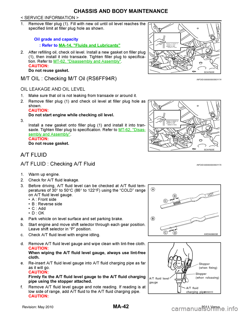
1. Remove filler plug (1). Fill with new oil until oil level reaches thespecified limit at filler plug hole as shown.
2. After refilling oil, check oil level. Install a new gasket on filler plug (1), then install it into transaxle. Tighten filler plug to specifica-
tion. Refer to MT-62, "
Disassembly and Assembly".
CAUTION:
Do not reuse gasket.
M/T OIL : Checking M/T Oil (RS6FF94R)INFOID:0000000005931174
OIL LEAKAGE AND OIL LEVEL
1. Make sure that oil is not leaking from transaxle or around it.
2. Remove filler plug (1) and check oil level at filler plug hole as shown.
CAUTION:
Do not start engine wh ile checking oil level.
3. Install a new gasket onto filler plug (1) and install it into tran-
saxle. Tighten filler plug to specification. Refer to MT-62, "
Disas-
sembly and Assembly".
CAUTION:
Do not reuse gasket.
A/T FLUID
A/T FLUID : Checking A/T FluidINFOID:0000000005931175
1. Warm up engine.
2. Check for A/T fluid leakage.
3. Before driving, A/T fluid level can be checked at A/T fluid tem- peratures of 30 ° to 50 °C (86° to 122° F) using the “COLD” range
on A/T fluid level gauge.
• A : Front side
• B : Reverse side
• C : Add
• D : OK
a. Park vehicle on level surface and set parking brake.
b. Start engine and move shift selector through each gear position. Leave shift selector in “P” position.
c. Check A/T fluid level with engine idling.
d. Remove A/T fluid level gauge and wipe clean with lint-free cloth. CAUTION:
When wiping the A/T fluid level gauge, always use lint-free
cloth.
e. Re-insert A/T fluid level gauge into A/T fluid charging pipe as far as it will go.
CAUTION:
Firmly fix the A/T fluid level gauge to the A/T fluid charging
pipe using the stopper attached.
f. Remove A/T fluid level gauge and note reading. If reading is at low side of range, add A/T fluid to the A/T fluid charging pipe.
CAUTION:Oil grade and capacity
: Refer to MA-14, "
Fluids and Lubricants"
SCIA7623E
SCIA7623E
AWDIA0660GB
SMA051D
Revision: May 2010 2011 Versa
Page 3218 of 3787
CHASSIS AND BODY MAINTENANCEMA-47
< SERVICE INFORMATION >
C
DE
F
G H
I
J
K
M A
B
MA
N
O P
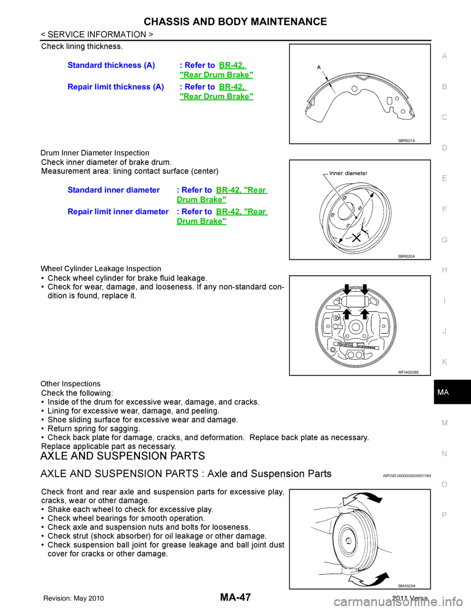
Check lining thickness.
Drum Inner Diameter Inspection
Check inner diameter of brake drum.
Measurement area: lining contact surface (center)
Wheel Cylinder Leakage Inspection
• Check wheel cylinder for brake fluid leakage.
• Check for wear, damage, and looseness. If any non-standard con- dition is found, replace it.
Other Inspections
Check the following:
• Inside of the drum for excessive wear, damage, and cracks.
• Lining for excessive wear, damage, and peeling.
• Shoe sliding surface for excessive wear and damage.
• Return spring for sagging.
• Check back plate for damage, cracks, and deformation. Replace back plate as necessary.
Replace applicable part as necessary.
AXLE AND SUSPENSION PARTS
AXLE AND SUSPENSION PARTS : Axle and Suspension PartsINFOID:0000000005931184
Check front and rear axle and suspension parts for excessive play,
cracks, wear or other damage.
• Shake each wheel to check for excessive play.
• Check wheel bearings for smooth operation.
• Check axle and suspension nuts and bolts for looseness.
• Check strut (shock absorber) for oil leakage or other damage.
• Check suspension ball joint for grease leakage and ball joint dust
cover for cracks or other damage. Standard thickness (A) : Refer to
BR-42,
"Rear Drum Brake"
Repair limit thickness (A) : Refer toBR-42,
"Rear Drum Brake"
SBR021A
Standard inner diameter : Refer toBR-42, "Rear
Drum Brake"
Repair limit inner diameter : Refer toBR-42, "Rear
Drum Brake"
SBR022A
WFIA0528E
SMA525A
Revision: May 2010 2011 Versa
Page 3233 of 3787

MT-12
< SERVICE INFORMATION >[RS5F91R]
SIDE OIL SEAL
SIDE OIL SEAL
Removal and InstallationINFOID:0000000005929665
REMOVAL
1. Remove front drive shafts from transaxle assembly. Refer to
FAX-9, "Removal and Installation (Left Side)"
and FAX-10, "Removal and Installation (Right Side)".
2. Remove differential side oil seal (1) using suitable tool. CAUTION:
Do not damage transaxle case or clutch housing.
INSTALLATION
Installation is in the reverse order of removal.
• B: Transaxle case side
• C: Clutch housing side
CAUTION:
• Do not reuse differential side oil seal
• Never incline differential side oil seal.
• Never damage clutch housing and transaxle case.
PCIB1505E
Tool number KV32500QAA ( – ) B.vi 1666-B
Dimension
L
1: 5.7 – 6.3 mm (0.224 – 0.248 in)
L
2: 2.4 – 3.0 mm (0.094 – 0.118 in)
JPDIC0401ZZ
Revision: May 2010 2011 Versa
Page 3238 of 3787

TRANSAXLE ASSEMBLYMT-17
< SERVICE INFORMATION > [RS5F91R]
D
E
F
G H
I
J
K L
M A
B
MT
N
O P
TRANSAXLE ASSEMBLY
Exploded ViewINFOID:0000000005929672
Removal and InstallationINFOID:0000000005929673
CAUTION:
If transaxle assembly is removed from the vehicle , always replace CSC (Concentric Slave Cylinder).
Return CSC insert to original pos ition to remove transaxle assembly. Du st on clutch disc sliding parts
may damage seal of CSC and may cau se clutch fluid leakage. Refer to CL-13, "
Removal and Installa-
tion".
REMOVAL
1. Drain clutch fluid and remove clutch tube from CSC. Refer to CL-13, "Removal and Installation".
CAUTION:
Do not depress clutch pedal during removal procedure.
2. Remove the engine and transaxle as an assembly from the vehicle. Refer t\
o EM-82, "
Removal and Instal-
lation".
3. Remove the transaxle to engine and engine to transaxle bolts.
4. Separate the transaxle assembly from the engine.
INSTALLATION
Installation is in the reverse order of removal.
1. LH engine mount bracket (transaxle side) 2. Transaxle assembly 3. Rear engine mount bracket
4. Washer 5. Rear torque rod Front
: Refer to installation.
PCIB1514E
Revision: May 2010
2011 Versa
Page 3241 of 3787

MT-20
< SERVICE INFORMATION >[RS5F91R]
TRANSAXLE ASSEMBLY
1. Input shaft front bearing 2. Input shaft
3. Snap ring
4. Input shaft rear bearing 5. Adapter plate 6. Bushing
7. 5th input gear 8. 5th-reverse baulk ring 9. Synchronizer lever
10. 5th-reverse synchronizer hub 11. 5th-reverse coupling sleeve 12. Retaining pin
13. Reverse gear assembly Replace parts as a set
JPDIC0480GB
JPDIC0531GB
Revision: May 2010 2011 Versa
Page 3242 of 3787

TRANSAXLE ASSEMBLYMT-21
< SERVICE INFORMATION > [RS5F91R]
D
E
F
G H
I
J
K L
M A
B
MT
N
O P
Shift Control Component
Final Drive Component
1. Mainshaft front bearing 2. Mainshaft
3. 1st main gear
4. 1st inner baulk ring 5. 1st synchronizer cone 6. 1st outer baulk ring
7. 1st-2nd synchronizer hub 8. 1st-2nd coupling sleeve 9. Spring
10. Insert key 11. 2nd outer baulk ring 12. 2nd synchronizer cone
13. 2nd inner baulk ring 14. Snap ring 15. Thrust washer
16. 2nd main gear 17. 3rd main gear 18. 3rd baulk ring
19. 3rd-4th synchronizer hub 20. 3rd-4th coupling sleeve 21. 4th baulk ring
22. 4th main gear 23. Spacer 24. Mainshaft rear bearing
25. 5th main gear Replace parts as a set
1. Retaining pin2. 1st-2nd shift fork 3. Bushing
4. 1st-2nd fork rod 5. Lock pin 6. 5th-reverse fork rod
7. 5th-reverse shift fork 8. Check ball 9. 3rd-4th shift fork
10. 3rd-4th fork rod 11. Control shaft 12. O-ring
13. Selector 14. Check ball plug 15. Bushing
16. Spring 17. Gear catch Replace parts as a set
JPDIC0485GB
Revision: May 2010 2011 Versa